Page 295 of 696
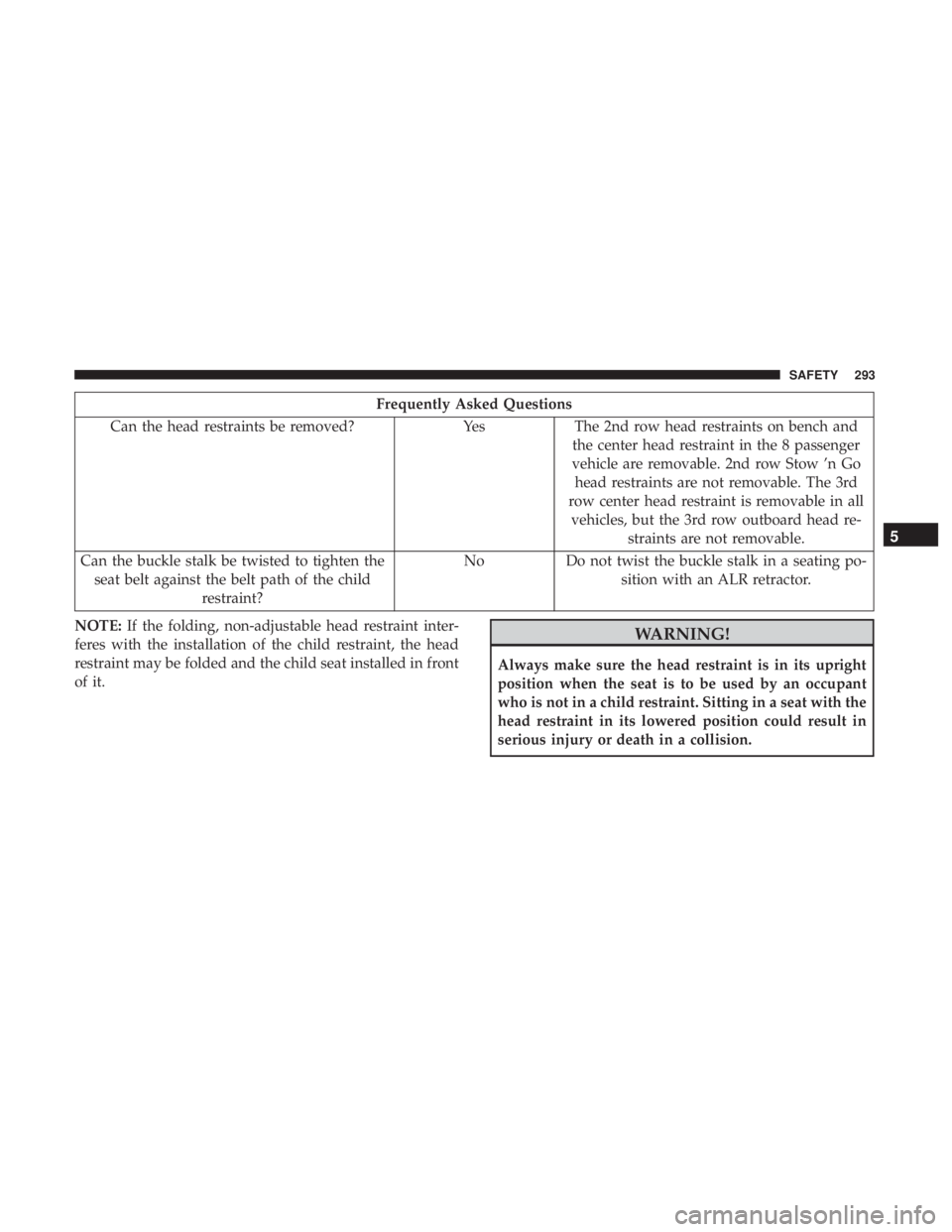
Frequently Asked Questions
Can the head restraints be removed? YesThe 2nd row head restraints on bench and
the center head restraint in the 8 passenger
vehicle are removable. 2nd row Stow ’n Go head restraints are not removable. The 3rd
row center head restraint is removable in all vehicles, but the 3rd row outboard head re- straints are not removable.
Can the buckle stalk be twisted to tighten the seat belt against the belt path of the child restraint? No
Do not twist the buckle stalk in a seating po-
sition with an ALR retractor.
NOTE: If the folding, non-adjustable head restraint inter-
feres with the installation of the child restraint, the head
restraint may be folded and the child seat installed in front
of it.
WARNING!
Always make sure the head restraint is in its upright
position when the seat is to be used by an occupant
who is not in a child restraint. Sitting in a seat with the
head restraint in its lowered position could result in
serious injury or death in a collision.
5
SAFETY 293
Page 300 of 696
2. Route the tether strap to provide the most direct path forthe strap between the anchor and the child seat. If your
vehicle is equipped with adjustable rear head restraints,
raise the head restraint, and where possible, route the
tether strap under the head restraint and between the
two posts. If not possible, lower the head restraint and
pass the tether strap around the outboard side of the
head restraint.
3. Attach the tether strap hook of the child restraint to the top tether anchorage as shown in the diagram. 4. Remove slack in the tether strap according to the child
restraint manufacturer ’s instructions.
WARNING!
•An incorrectly anchored tether strap could lead to
increased head motion and possible injury to the
child. Use only the anchorage position directly be-
hind the child seat to secure a child restraint top
tether strap.
(Continued)
Top Tether Anchorage Locations 3rd Row
Rear Seat Tether Strap Attachment
(Second Row Anchorage Shown)
298 SAFETY
Page 301 of 696

WARNING!(Continued)
•If your vehicle is equipped with a split rear seat,
make sure the tether strap does not slip into the
opening between the seatbacks as you remove slack
in the strap.
Third Row Tether Attachment
The tether anchorage found on the back of the 60% seat in
the third row may be used by either the left outboard or the
center seating position. Only tether one child restraint to
the tether anchorage at a time.
To connect the tether strap hook to the tether anchorage for
either seating position on the 60% third row seat:
1. Route the tether strap to provide the most direct path for
the strap between the anchor and the child seat.
2. If the car seat is in the center, raise the center head restraint and route the tether strap around the inboard
(left) side of the head restraint support posts, as shown
in the diagram. 3. Attach the tether strap hook of the child restraint to the
top tether anchorage as shown in the diagram.
4. Remove slack in the tether strap according to the child restraint manufacturer ’s instructions.
Center Tether Attachment – 3rd Row
5
SAFETY 299
Page 338 of 696
WARNING!
Leaving the Adaptive Cruise Control (ACC) system on
when not in use is dangerous. You could accidentally
set the system or cause it to go faster than you want.
You could lose control and have a collision. Always
leave the system off when you are not using it.
To Set A Desired ACC Speed
When the vehicle reaches the speed desired, push the SET
(+)button or the SET (-)button and release. The instrument
cluster display will show the set speed. If the system is set when the vehicle speed is below 20 mph
(32 km/h), the set speed shall be defaulted to 20 mph
(32 km/h). If the system is set when the vehicle speed is
above 20 mph (32 km/h), the set speed shall be the current
speed of the vehicle.
NOTE:
ACC cannot be set if there is a stationary vehicle in
front of your vehicle in close proximity.
Remove your foot from the accelerator pedal, after the
ACC has been set. If you do not, the vehicle may continue
to accelerate beyond the set speed. If this occurs:
• The message “ACC DRIVER OVERRIDE” will display
in the instrument cluster display.
• The system will not be controlling the distance between
your vehicle and the vehicle ahead. The vehicle speed
will only be determined by the position of the accelera-
tor pedal.
To Cancel
The following conditions cancel the system:
•The brake pedal is applied.
• The CANC (cancel) button is pushed.
• An Anti-Lock Brake System (ABS) event occurs.
Adaptive Cruise Control Off
336 STARTING AND OPERATING
Page 435 of 696

Replacing Exterior Bulbs
High Intensity Discharge (HID) Headlamps — If
Equipped
The headlamps contain a type of high voltage discharge
light source. High voltage can remain in the circuit even
with the headlamp switch off. Because of this, you should
not attempt to service a HID headlamp light source your-
self. If an HID headlamp light source fails, take your
vehicle to an authorized dealer for service.
NOTE:On vehicles equipped with HID headlamps, when
the headlamps are turned on, there is a blue hue to the
lights. This diminishes and becomes more white after
approximately 10 seconds, as the system charges.
WARNING!
A transient high voltage occurs at the bulb sockets of
HID headlamps when the headlamp switch is turned
ON. It may cause serious electrical shock or electrocu-
tion if not serviced properly. See your authorized
dealer for service.
Halogen Headlamps
1. Reach behind the headlamp housing to access the headlamp bulb cap.
2. Firmly grasp the headlamp bulb cap and rotate it counterclockwise to unlock it.
3. Firmly grasp the headlamp bulb socket assembly and rotate counterclockwise to remove from the housing.
Headlamp Bulb Cap
7
IN CASE OF EMERGENCY 433
Page 439 of 696
CAUTION!
Do not touch the new bulb with your fingers. Oil
contamination will severely shorten bulb life. If the
bulb comes in contact with any oily surface, clean the
bulb with rubbing alcohol.
5. Install the front fog lamp bulb into the front fog lamp housing, and rotate the bulb clockwise to lock it in place.
6. Position the inner wheel liner in place and install fasteners.
Rear Liftgate Mounted Back-Up Lamps And Tail
Lamps (If Bulb Equipped)
1. Raise the liftgate.
2. Use a fiber stick or flat blade screw driver to pry off thebulb access cover on the lower liftgate trim.
3. Back-up lamps/tail lamp (if bulb equipped) are now visible. Rotate socket(s) counter clockwise.
4. Remove/replace bulb(s).
5. Reinstall the socket(s)
6. Reverse process to reinstall the liftgate trim.
Rear Bodyside Mounted Taillamps
1. Raise the liftgate.
2. Remove two torx head screws on bodyside lamp using a T30 screwdriver.
3. Remove lamp from vehicle body and locate bulb socket on rear of lamp. Rotate socket counter-clockwise.
4. Remove/replace bulb(s).
5. Reinstall the socket(s)
6. Reverse process to reinstall the lamp onto vehicle.
Center High-Mounted Stop Lamp (CHMSL)
The center high-mounted stop lamp is an LED assembly.
See your authorized dealer for replacement.
Rear License Lamp
The rear license lamps are LED. See your authorized dealer
for replacement.
7
IN CASE OF EMERGENCY 437
Page 454 of 696
CAUTION!
Do not attempt to raise the vehicle by jacking on
locations other than those indicated.
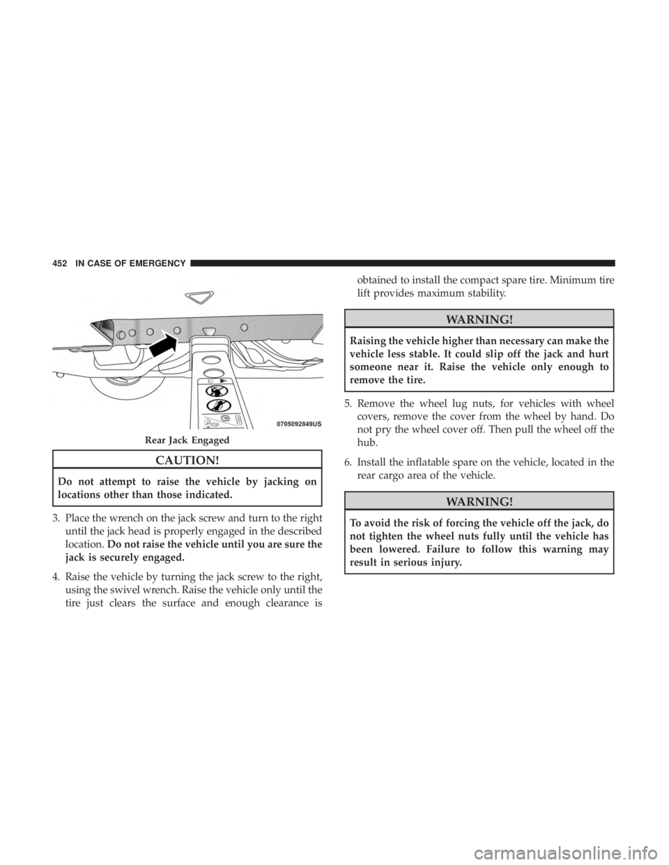
3. Place the wrench on the jack screw and turn to the right until the jack head is properly engaged in the described
location. Do not raise the vehicle until you are sure the
jack is securely engaged.
4. Raise the vehicle by turning the jack screw to the right, using the swivel wrench. Raise the vehicle only until the
tire just clears the surface and enough clearance is obtained to install the compact spare tire. Minimum tire
lift provides maximum stability.
WARNING!
Raising the vehicle higher than necessary can make the
vehicle less stable. It could slip off the jack and hurt
someone near it. Raise the vehicle only enough to
remove the tire.
5. Remove the wheel lug nuts, for vehicles with wheel covers, remove the cover from the wheel by hand. Do
not pry the wheel cover off. Then pull the wheel off the
hub.
6. Install the inflatable spare on the vehicle, located in the rear cargo area of the vehicle.
WARNING!
To avoid the risk of forcing the vehicle off the jack, do
not tighten the wheel nuts fully until the vehicle has
been lowered. Failure to follow this warning may
result in serious injury.
Rear Jack Engaged
452 IN CASE OF EMERGENCY
Page 545 of 696
The following maintenance recommendations will enable
you to obtain maximum benefit from the corrosion resis-
tance built into your vehicle.
What Causes Corrosion?
Corrosion is the result of deterioration or removal of paint
and protective coatings from your vehicle.
The most common causes are:
•Road salt, dirt and moisture accumulation.
• Stone and gravel impact.
• Insects, tree sap and tar.
• Salt in the air near seacoast localities.
• Atmospheric fallout/industrial pollutants.
Body And Underbody Maintenance
Cleaning Headlights
Your vehicle is equipped with plastic headlights and fog
lights that are lighter and less susceptible to stone breakage
than glass headlights.
Plastic is not as scratch resistant as glass and therefore
different lens cleaning procedures must be followed. To minimize the possibility of scratching the lenses and
reducing light output, avoid wiping with a dry cloth. To
remove road dirt, wash with a mild soap solution followed
by rinsing.
Do not use abrasive cleaning components, solvents, steel
wool or other aggressive material to clean the lenses.
Preserving The Bodywork
Washing
•
Wash your vehicle regularly. Always wash your vehicle
in the shade using Mopar Car Wash, or a mild car wash
soap, and rinse the panels completely with clear water.
• If insects, tar, or other similar deposits have accumulated
on your vehicle, use Mopar Super Kleen Bug and Tar
Remover to remove.
• Use a high quality cleaner wax, such as Mopar Cleaner
Wax to remove road film, stains and to protect your
paint finish. Take care never to scratch the paint.
• Avoid using abrasive compounds and power buffing
that may diminish the gloss or thin out the paint finish.
8
SERVICING AND MAINTENANCE 543