Page 45 of 696

•Buttons located:
– In the overhead console
– Just inside the sliding door
– On the outside handle
Push the button on the key fob twice within five
seconds to open, close, or reverse a power sliding
door.
The key fob and the overhead console button will operate
the door when the door is locked. All other ways require
the sliding door to be unlocked. If the vehicle is equipped
with Passive Entry, pressing the button on the outside
handle or Hands-Free feature (if equipped) will unlock and
open the sliding door, with a valid Passive Entry key fob
within 5 ft (1.5 m) of the door handle.
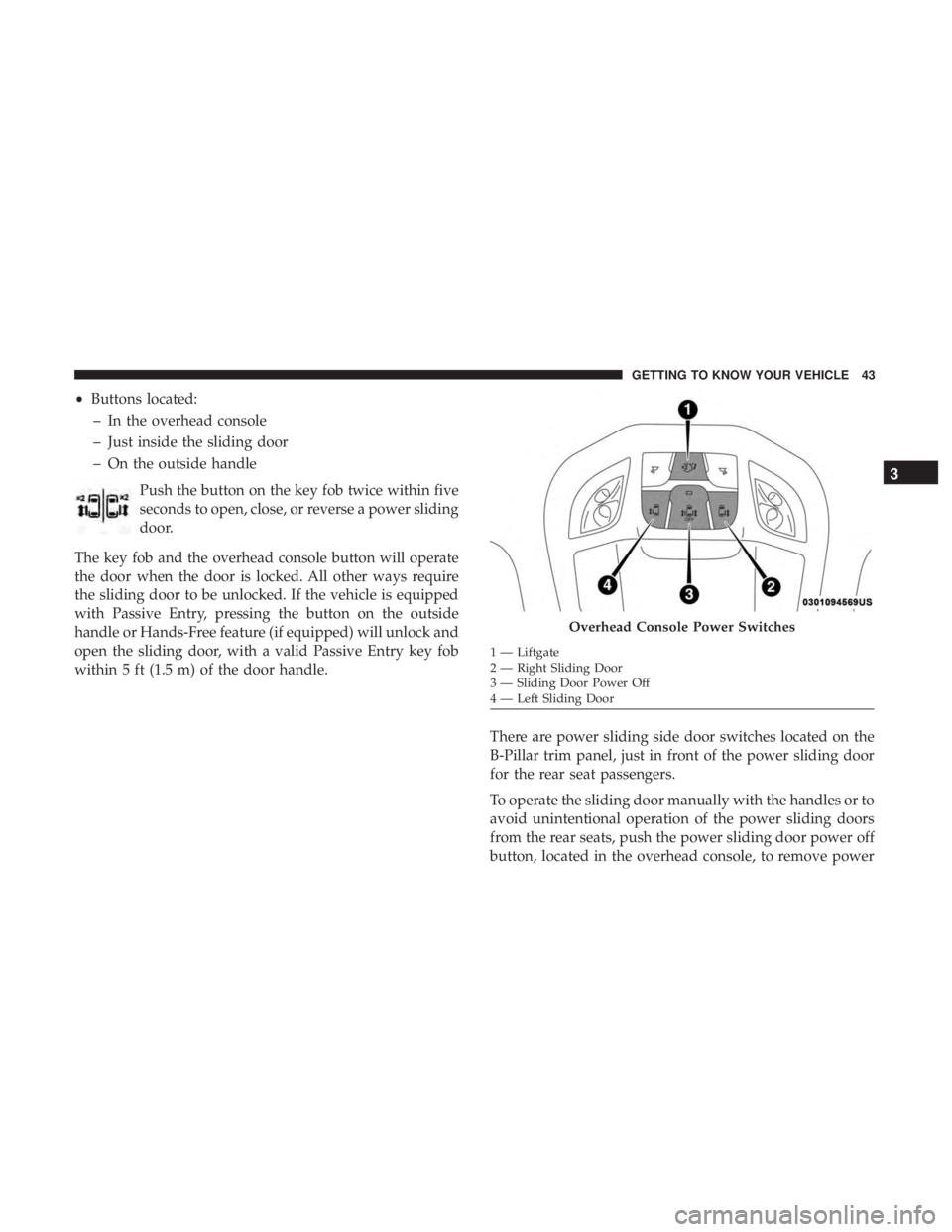
There are power sliding side door switches located on the
B-Pillar trim panel, just in front of the power sliding door
for the rear seat passengers.
To operate the sliding door manually with the handles or to
avoid unintentional operation of the power sliding doors
from the rear seats, push the power sliding door power off
button, located in the overhead console, to remove power
Overhead Console Power Switches
1 — Liftgate
2 — Right Sliding Door
3 — Sliding Door Power Off
4 — Left Sliding Door
3
GETTING TO KNOW YOUR VEHICLE 43
Page 77 of 696
NOTE:
•The seatback may lock into the fold flat position. Use the
recline lever to unlock the seatback.
• When returning the seat to the original position, the
headrest must be folded back to the original position.Second Row Removable 8th Seat — If Equipped
While the 8th seat does not stow in the floor, it is foldable
and removable for added cargo space.
The release strap is located on the front of the seat, near the
floor. To remove the seat, pull the release strap to release
the rear latches. The seat assembly can now be removed
from the vehicle by moving it in a rearward direction from
the detent positions in the floor.
Fold Headrest To Upward Position
Second Row 8th Seat Fold Flat Strap
3
GETTING TO KNOW YOUR VEHICLE 75
Page 84 of 696

Plastic Grocery Bag Retainer Hooks
Retainer hooks which will hold plastic grocery bag handles
are built into the seatbacks of the first and third row rear
seats. The floor supports the partial weight of the bagged
goods.
HEAD RESTRAINTS
Head restraints are designed to reduce the risk of injury by
restricting head movement in the event of a rear impact.
Head restraints should be adjusted so that the top of the
head restraint is located above the top of your ear.
WARNING!
•All occupants, including the driver, should not oper-
ate a vehicle or sit in a vehicle’s seat until the head
restraints are placed in their proper positions in
order to minimize the risk of neck injury in the event
of a crash.
• Head restraints should never be adjusted while the
vehicle is in motion. Driving a vehicle with the head
restraints improperly adjusted or removed could
cause serious injury or death in the event of a
collision.
Head Restraints — Front Seats
The front driver and passenger seats are equipped with
four-way head restraints.
To raise the head restraint, pull upward on the head
restraint. To lower the head restraint, push the adjustment
button, located at the base of the head restraint, and push
downward. The front head restraints are also adjustable
forward and rearward. To adjust forward, pull the head
restraint toward the front of the vehicle to desired position.
To adjust the head restraint rearward, pull forward on the
head restraint to furthest forward position and head re-
straint will reset to furthest rearward position.
NOTE: To remove the head restraint, raise it as far as it can
go. Then, push the release button and the adjustment
button at the base of each post while pulling the head
restraint up. Seatback angle may need to be adjusted to
fully remove the head restraint. To reinstall the head
restraint, put the head restraint posts into the holes and
push downward. Then, adjust the head restraint to the
appropriate height.
82 GETTING TO KNOW YOUR VEHICLE
Page 87 of 696

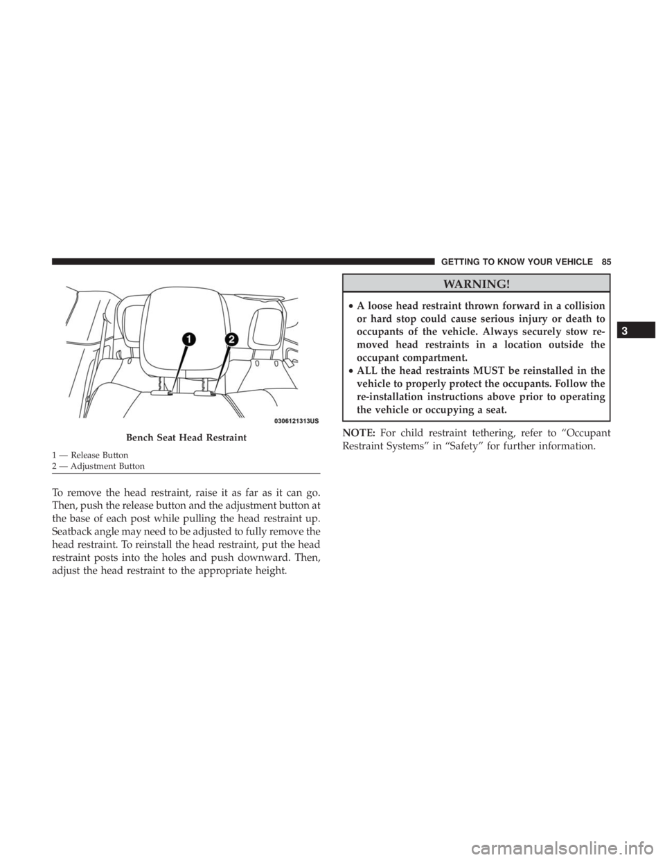
To remove the head restraint, raise it as far as it can go.
Then, push the release button and the adjustment button at
the base of each post while pulling the head restraint up.
Seatback angle may need to be adjusted to fully remove the
head restraint. To reinstall the head restraint, put the head
restraint posts into the holes and push downward. Then,
adjust the head restraint to the appropriate height.
WARNING!
•A loose head restraint thrown forward in a collision
or hard stop could cause serious injury or death to
occupants of the vehicle. Always securely stow re-
moved head restraints in a location outside the
occupant compartment.
• ALL the head restraints MUST be reinstalled in the
vehicle to properly protect the occupants. Follow the
re-installation instructions above prior to operating
the vehicle or occupying a seat.
NOTE: For child restraint tethering, refer to “Occupant
Restraint Systems” in “Safety” for further information.
Bench Seat Head Restraint
1 — Release Button
2 — Adjustment Button
3
GETTING TO KNOW YOUR VEHICLE 85
Page 88 of 696
Head Restraints — Third Row
The outboard head restraints can be manually folded
forward for improved rearward visibility. Pull the release
strap to fold them forward.
NOTE:
•The head restraints must be raised manually when
occupying the third row.
• Do not fold if there are passengers seated in the third
row seats. The head restraint in the center position can be raised and
lowered for tether routing or height adjustment. Refer to
“Occupant Restraint Systems” in “Safety” for further infor-
mation.
NOTE:
To remove the center head restraint, raise it as far as
it can go. Then, push the release button and the adjustment
button at the base of each post while pulling the head
restraint up. To reinstall the head restraint, put the head
restraint posts into the holes and push downward. Then,
using the adjustment button, adjust the head restraint to
the appropriate height.
Release Strap
Adjustment Button
86 GETTING TO KNOW YOUR VEHICLE
Page 103 of 696

Parade Mode (Daytime Brightness Feature)
Rotate the instrument panel dimmer control upward to the
first detent. This feature brightens all text displays such as
the odometer, instrument cluster display, and radio when
the position lights or headlights are on.
WINDSHIELD WIPER AND WASHERS
Windshield Wiper Operation
The wipers and washers are operated by a switch within
the wiper lever. Rotate the end of the lever upward, to the
first detent past the intermittent settings for low-speed
wiper operation. Rotate the end of the lever upward to the
second detent past the intermittent settings for high-speed
wiper operation.NOTE:
Always remove any buildup of snow that prevents
the windshield wiper blades from returning to the off
position. If the windshield wiper switch is turned off and
the blades cannot return to the off position, damage to the
wiper motor may occur.
WARNING!
Sudden loss of visibility through the windshield could
lead to a collision. You might not see other vehicles or
other obstacles. To avoid sudden icing of the windshield
during freezing weather, warm the windshield with the
defroster before and during windshield washer use.
Washer And Wiper Controls
3
GETTING TO KNOW YOUR VEHICLE 101
Page 250 of 696
1. Remove the mini-latch plate and regular latch platefrom its stowed position in the headliner slightly behind
the second or third row seat. 2. Grasp the mini-latch plate and pull the seat belt over the
seat.
Mini-Latch Stowage
Mini-Latch Plate
248 SAFETY
Page 276 of 696

Your vehicle may also be designed to perform any of these
other functions in response to the Enhanced Accident
Response System:
•Turn off the Fuel Filter Heater, Turn off the HVAC
Blower Motor, Close the HVAC Circulation Door
• Cut off battery power to the:
• Engine
• Electric Motor (if equipped)
• Electric power steering
• Brake booster
• Electric park brake
• Automatic transmission gear selector
• Horn
• Front wiper
• Headlamp washer pump
NOTE: After an accident, remember to cycle the ignition to
the STOP (OFF/LOCK) position and remove the key from
the ignition switch to avoid draining the battery. Carefully
check the vehicle for fuel leaks in the engine compartment
and on the ground near the engine compartment and fuel
tank before resetting the system and starting the engine. If
there are no fuel leaks or damage to the vehicle electrical
devices (e.g. headlights) after an accident, reset the system by following the procedure described below. If you have
any doubt, contact an authorized dealer.
Enhanced Accident Response System Reset
Procedure
In order to reset the Enhanced Accident Response System
functions after an event, the ignition switch must be changed
from ignition START or ON/RUN to ignition OFF. Carefully
check the vehicle for fuel leaks in the engine compartment
and on the ground near the engine compartment and fuel
tank before resetting the system and starting the engine.
Maintaining Your Air Bag System
WARNING!
•
Modifications to any part of the air bag system could
cause it to fail when you need it. You could be
injured if the air bag system is not there to protect
you. Do not modify the components or wiring, in-
cluding adding any kind of badges or stickers to the
steering wheel hub trim cover or the upper passenger
side of the instrument panel. Do not modify the front
bumper, vehicle body structure, or add aftermarket
side steps or running boards.
(Continued)
274 SAFETY