Page 10 of 614
FRONT VIEW
Front View
1 — Hood/Engine Compartment
2 — Headlights
3 — Wheels/Tires
4 — Windshield5 — Charging Port Door
6 — Exterior Mirrors
7 — Doors
8 — Fuel Door
8 GRAPHICAL TABLE OF CONTENTS
Page 37 of 614

Hybrid Electric Pages
Within your Uconnect 4C/4C NAV system is the “Hybrid
Electric Pages” App that allows you to see your vehicle’s
power flow, understand your drive history, and set an
EVSE charging schedule for your vehicle’s high voltage
battery. To access this app, press the “Apps” button on the
main menu bar of the radio’s touch screen, and locate the
“Hybrid Electric” App. Pressing the “Hybrid Electric
Pages” App brings you to a set of three pages: Power Flow,
Driving History, and Charging Schedule.
Power Flow
The first screen within the “Hybrid Electric Pages” App is
the Power Flow screen. The Power Flow screen shows the
current power readings for all of the following:
•Engine - Shows the amount of power (in kW) the engine
is generating. Based on vehicle operating conditions, this
power is used to: propel the vehicle, provide passenger
compartment heating & cooling, power vehicle electrical
loads, and charge the High Voltage Battery. Engine
operation is controlled to maximize fuel economy.
• Battery - Shows the amount of power (in kW) the high
voltage battery is currently providing/absorbing. A
negative kW indicates the vehicle’s high voltage battery
is charging.
• Climate - Shows the amount of power (in kW) the
climate control system is using to maintain the current
interior temperature.
Hybrid Electric Pages App Location
3
GETTING TO KNOW YOUR VEHICLE 35
Page 50 of 614

Conditions Causing Engine To Run
•Maintaining Hybrid Battery SOC
• Provide Maximum Vehicle Acceleration
• Provide Maximum Passenger Compartment Heating
• Maintain Exhaust System Catalyst Temperature (after
engine start in current ignition cycle - emissions require-
ment)
• Engine Temporarily Operating in “Fuel and Oil Mainte-
nance Mode”
• Hood Opened with Ignition in Run Post-Start Mode
(eliminate unexpected engine start-ups)
In case the ignition switch does not change with the push
of a button, the key fob may have a low or dead battery. In
this situation, a back up method can be used to operate the
ignition switch. Put the nose side (side opposite of the
emergency key) of the key fob against the ENGINE
START/STOP button and push to operate the ignition
switch.
WARNING!
• When leaving the vehicle, always remove the key fob
from the vehicle and lock your vehicle.
• Never leave children alone in a vehicle, or with
access to an unlocked vehicle.
• Allowing children to be in a vehicle unattended is
dangerous for a number of reasons. A child or others
could be seriously or fatally injured. Children
should be warned not to touch the parking brake,
brake pedal or the gear selector.
(Continued)
Keyless Push Button Ignition
48 GETTING TO KNOW YOUR VEHICLE
Page 52 of 614

Remote Start Cancel Message — If Equipped
The following messages will display in the instrument
cluster if the vehicle fails to remote start or exits remote
start prematurely:
•Remote Start Cancelled — Door Open
(Prior to remote start attempt)
• Remote Start Cancelled — Hood Open
• Remote Start Cancelled — Fuel Low
• Remote Start Cancelled — Liftgate Open
• Remote Start Cancelled — Time Expired
• Remote Start Disabled — Start Vehicle To Reset
The message will stay active until the ignition is placed in
the ON/RUN position.
How To Use Remote Start
All of the following conditions must be met before the
vehicle will remote start:
• Gear Selector in PARK
• Doors closed
• Hood closed
• Liftgate closed •
Hazard switch off
• Brake switch inactive (brake pedal not pushed)
• 12 volt battery at an acceptable charge level
• Key fob PANIC button not pushed
• System not disabled from previous remote start event
• Vehicle alarm system indicator flashing
• Ignition in STOP/OFF position
• Fuel level meets minimum requirement
• MIL lamp is OFF, Vehicle is in propulsion system active
WARNING!
•Do not start or run an engine in a closed garage or
confined area. Exhaust gas contains Carbon Monox-
ide (CO) which is odorless and colorless. Carbon
Monoxide is poisonous and can cause serious injury
or death when inhaled.
• Keep key fobs away from children. Operation of the
Remote Start System, windows, door locks or other
controls could cause serious injury or death.
50 GETTING TO KNOW YOUR VEHICLE
Page 64 of 614

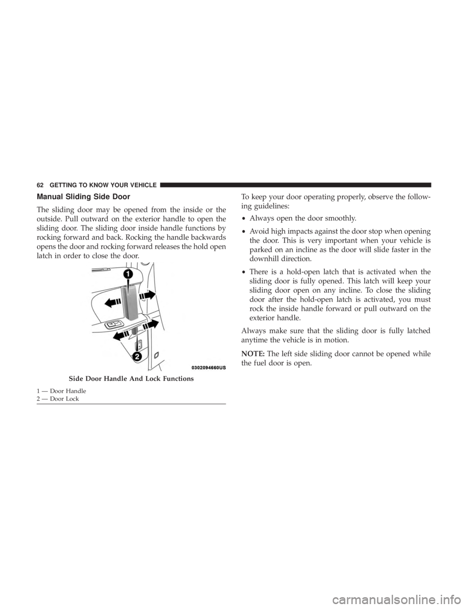
Manual Sliding Side Door
The sliding door may be opened from the inside or the
outside. Pull outward on the exterior handle to open the
sliding door. The sliding door inside handle functions by
rocking forward and back. Rocking the handle backwards
opens the door and rocking forward releases the hold open
latch in order to close the door.To keep your door operating properly, observe the follow-
ing guidelines:
•
Always open the door smoothly.
• Avoid high impacts against the door stop when opening
the door. This is very important when your vehicle is
parked on an incline as the door will slide faster in the
downhill direction.
• There is a hold-open latch that is activated when the
sliding door is fully opened. This latch will keep your
sliding door open on any incline. To close the sliding
door after the hold-open latch is activated, you must
rock the inside handle forward or pull outward on the
exterior handle.
Always make sure that the sliding door is fully latched
anytime the vehicle is in motion.
NOTE: The left side sliding door cannot be opened while
the fuel door is open.
Side Door Handle And Lock Functions
1 — Door Handle
2 — Door Lock 62 GETTING TO KNOW YOUR VEHICLE
Page 111 of 614

IconDescription
Mix Mode
Mix Mode
Air is directed through the floor, defrost, and side window demister outlets. This setting works
best in cold or snowy conditions that require extra heat to the windshield. This setting is good
for maintaining comfort while reducing moisture on the windshield.
Climate Control OFF Button
Press and release this button to turn the Climate Controls off.
Climate Control Functions
A/C (Air Conditioning)
The Air Conditioning (A/C) button allows the operator to
manually activate or deactivate the air conditioning sys-
tem. When the air conditioning system is turned on, cool
dehumidified air will flow through the outlets into the
cabin. For improved fuel economy, press the A/C button to
turn off the air conditioning and manually adjust the
blower and airflow mode settings. Also, make sure to select
only Panel, Bi-Level, or Floor modes. NOTE:
•
If fog or mist appears on the windshield or side glass,
select Defrost mode, and increase blower speed if
needed.
• If your air conditioning performance seems lower than
expected, check the front of the A/C condenser (located
in front of the radiator), for an accumulation of dirt or
insects. Clean with a gentle water spray from the front of
the radiator and through the condenser.
3
GETTING TO KNOW YOUR VEHICLE 109
Page 159 of 614

GETTING TO KNOW YOUR INSTRUMENT PANEL
CONTENTS
�INSTRUMENT CLUSTER ..................158
▫ Instrument Cluster Descriptions ............159
� INSTRUMENT CLUSTER DISPLAY ...........160
▫ Instrument Cluster Display Location
And Controls ......................... .160
▫ Oil Life Reset ........................ .161
▫ Fuel And Oil Refresh Mode ................162
▫ KeySense Cluster Messages — If Equipped .....163
▫ Instrument Cluster Display Menu Items .......164
▫ Battery Saver On/Battery Saver Mode Message —
Electrical Load Reduction Actions —
If Equipped ......................... .170�
WARNING LIGHTS AND MESSAGES .........172
▫ Red Warning Lights .....................173
▫ Yellow Warning Lights ...................177
▫ Yellow Indicator Lights ...................182
▫ Green Indicator Lights ...................182
▫ White Indicator Lights ...................183
▫ Blue Indicator Lights ....................184
� ONBOARD DIAGNOSTIC SYSTEM — OBD II . . .184
▫ Onboard Diagnostic System (OBD II)
Cybersecurity ........................ .184
� EMISSIONS INSPECTION AND MAINTENANCE
PROGRAMS .......................... .1854
Page 161 of 614

Instrument Cluster Descriptions
1. % Power Gauge•Indicates vehicle power. The upper half of the gauge is
a summation of the engine and high voltage battery
power applied to move the vehicle. Bottom half indi-
cates when the high voltage battery is charging via
regenerative braking, while slowing the vehicle down.
2. Instrument Cluster Display •The instrument cluster display features a driver-
interactive display. When the appropriate conditions
exist, this display shows messages. Refer to “Instru-
ment Cluster Display” located in “Getting To Know
Your Instrument Panel” for further information.
3. Fuel Gauge •The gauge shows the level of fuel in the fuel tank when
the ignition switch is in the ON/RUN position.
•
The fuel pump symbol points to the side of the
vehicle where the fuel door is located.
4. Reconfigurable Screen With Four Customer Program- mable Options
• Battery % & Electric Range: shows values for electric
range and battery %, along with a teal gauge showing
battery % (state of charge 0-100%). •
Electric Range: shows electric range, along with a teal
gauge showing battery % (state of charge 0-100%).
• All Range: shows values for electric, hybrid and total
range, along with a white gauge showing the total
range.
• NONE
5. Reconfigurable Screen With 4 Options •Efficiency Coach: This gauge provides visual aware-
ness on how to achieve maximum energy efficiency
while driving. When accelerating or decelerating the
most efficient operation will be represented with the
gauge color being green. Less efficient operation will
be represented by yellow, followed by orange, as the
level of efficiency decreases.
• Charge/Power: This gauge represents the source of
the power utilized to accelerate the vehicle. The teal
outer ring represents the HV (High Voltage) battery
output during acceleration, and input power during
regeneration. The blue inner ring represents the engine
output power.
• Energy economy: this gauge represents the combined
MPG (km/L, L/100km) obtained through engine use
and MPG (km/L, L/100km) equivalent obtained
4
GETTING TO KNOW YOUR INSTRUMENT PANEL 159