Page 276 of 614
WARNING!(Continued)
•ONLY use the passenger ’s side floor mat on the
passenger ’s side floor area.
• ALWAYS make sure objects cannot fall or slide into
the driver ’s side floor area when the vehicle is
moving. Objects can become trapped under accelera-
tor, brake, or clutch pedals and could cause a loss of
vehicle control.
• NEVER place any objects under the floor mat (e.g.,
towels, keys, etc.). These objects could change the
position of the floor mat and may cause interference
with the accelerator, brake, or clutch pedals.
• If the vehicle carpet has been removed and re-
installed, always properly attach carpet to the floor
and check the floor mat fasteners are secure to the
vehicle carpet. Fully depress each pedal to check for
interference with the accelerator, brake, or clutch
pedals then re-install the floor mats.
• It is recommended to only use mild soap and water
to clean your floor mats. After cleaning, always check
your floor mat has been properly installed and is
secured to your vehicle using the floor mat fasteners
by lightly pulling mat.
Periodic Safety Checks You Should Make Outside
The Vehicle
Tires
Examine tires for excessive tread wear and uneven wear
patterns. Check for stones, nails, glass, or other objects
lodged in the tread or sidewall. Inspect the tread for cuts
and cracks. Inspect sidewalls for cuts, cracks, and bulges.
Check the wheel nuts for tightness. Check the tires (includ-
ing spare) for proper cold inflation pressure.
Lights
Have someone observe the operation of brake lights and
exterior lights while you work the controls. Check turn
signal and high beam indicator lights on the instrument
panel.
Door Latches
Check for proper closing, latching, and locking.
Fluid Leaks
Check area under the vehicle after overnight parking for
fuel, coolant, oil, or other fluid leaks. Also, if gasoline
fumes are detected or if fuel, or brake fluid leaks are
suspected. The cause should be located and corrected
immediately.
274 SAFETY
Page 279 of 614
▫Parallel Parking Space Assistance
Operation/Display ..................... .338
▫ Perpendicular Parking Space Assistance
Operation/Display ..................... .347
� LANESENSE — IF EQUIPPED ..............356
▫ LaneSense Operation ....................356
▫ Turning LaneSense On Or Off ..............357
▫ LaneSense Warning Message ...............357
▫ Changing LaneSense Status ................360
� PARKVIEW REAR BACK UP CAMERA —
IF EQUIPPED ......................... .360
� SURROUND VIEW CAMERA SYSTEM —
IF EQUIPPED ......................... .363�
REFUELING THE VEHICLE ................367
� VEHICLE LOADING .....................370
▫ Certification Label ..................... .370
� TRAILER TOWING ..................... .372
� RECREATIONAL TOWING (BEHIND
MOTORHOME, ETC.) ....................372
▫ Towing This Vehicle Behind Another Vehicle. . . .372
▫ Recreational Towing — All Models ..........373
� DRIVING TIPS ......................... .374
▫ Driving On Slippery Surfaces ..............374
▫ Driving Through Water ..................375
6
STARTING AND OPERATING 277
Page 369 of 614
REFUELING THE VEHICLE
1. Put the vehicle in the PARK postion.
2. Press the fuel filler door release button (located in thedriver’s door in the upper map pocket).
3. The button press will initiate a sequence of events to depressurize the fuel system. A message will display in
the cluster letting you know when the vehicle is ready to
be fueled. NOTE:
•After pushing the release button you will have 20 min-
utes to fuel the vehicle, beyond 20 minutes you will
need to press the release button again.
• The fuel door could take up to 15 seconds to open. It
may take longer to open in some situations, such as
high ambient temperatures.
• If you hear a hissing sound when the nozzle is inserted
into the filler pipe, wait to begin fueling the vehicle
until after the hissing sound stops.
Fuel Filler Door Release Switch
Instrument Cluster Message
6
STARTING AND OPERATING 367
Page 370 of 614
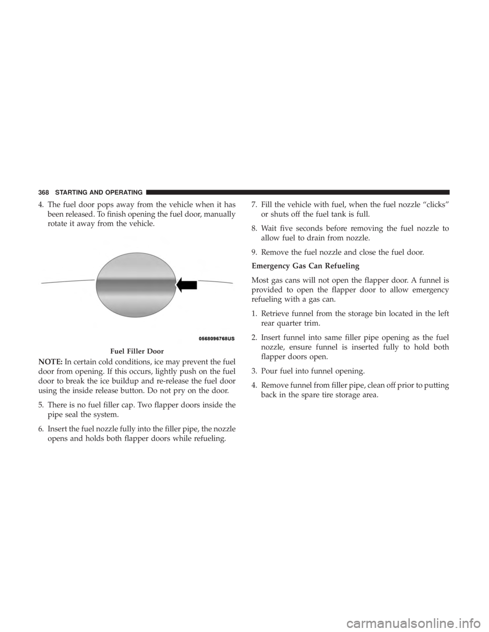
4. The fuel door pops away from the vehicle when it hasbeen released. To finish opening the fuel door, manually
rotate it away from the vehicle.
NOTE: In certain cold conditions, ice may prevent the fuel
door from opening. If this occurs, lightly push on the fuel
door to break the ice buildup and re-release the fuel door
using the inside release button. Do not pry on the door.
5. There is no fuel filler cap. Two flapper doors inside the pipe seal the system.
6. Insert the fuel nozzle fully into the filler pipe, the nozzle opens and holds both flapper doors while refueling. 7. Fill the vehicle with fuel, when the fuel nozzle “clicks”
or shuts off the fuel tank is full.
8. Wait five seconds before removing the fuel nozzle to allow fuel to drain from nozzle.
9. Remove the fuel nozzle and close the fuel door.
Emergency Gas Can Refueling
Most gas cans will not open the flapper door. A funnel is
provided to open the flapper door to allow emergency
refueling with a gas can.
1. Retrieve funnel from the storage bin located in the left rear quarter trim.
2. Insert funnel into same filler pipe opening as the fuel nozzle, ensure funnel is inserted fully to hold both
flapper doors open.
3. Pour fuel into funnel opening.
4. Remove funnel from filler pipe, clean off prior to putting back in the spare tire storage area.
Fuel Filler Door
368 STARTING AND OPERATING
Page 371 of 614
WARNING!
•Never have any smoking materials lit in or near the
vehicle when the fuel door is open or the tank is
being filled.
• Never add fuel when the engine is running. This is
in violation of most state and federal fire regulations
and may cause the “Malfunction Indicator Light” to
turn on.
• A fire may result if fuel is pumped into a portable
container that is inside of a vehicle. You could be
burned. Always place fuel containers on the ground
while filling.
CAUTION!
To avoid fuel spillage and overfilling, do not “top off”
the fuel tank after filling.
Emergency Fuel Door Release
1. Cycle the vehicle’s ignition to the RUN position (PSA not active)
NOTE: If this is not performed, then the tank vent valve
will not open. This will result in premature fuel pump
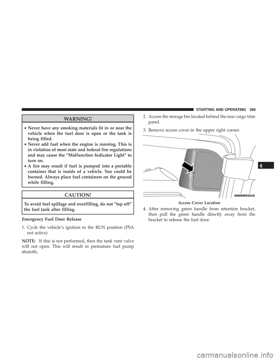
shutoffs. 2. Access the storage bin located behind the rear cargo trim
panel.
3. Remove access cover in the upper right corner.
4. After removing green handle from retention bracket, then pull the green handle directly away from the
bracket to release the fuel door.Access Cover Location
6
STARTING AND OPERATING 369
Page 372 of 614
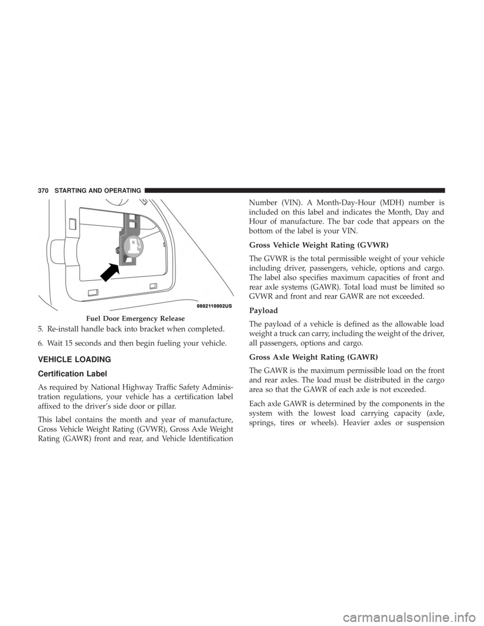
5. Re-install handle back into bracket when completed.
6. Wait 15 seconds and then begin fueling your vehicle.
VEHICLE LOADING
Certification Label
As required by National Highway Traffic Safety Adminis-
tration regulations, your vehicle has a certification label
affixed to the driver’s side door or pillar.
This label contains the month and year of manufacture,
Gross Vehicle Weight Rating (GVWR), Gross Axle Weight
Rating (GAWR) front and rear, and Vehicle IdentificationNumber (VIN). A Month-Day-Hour (MDH) number is
included on this label and indicates the Month, Day and
Hour of manufacture. The bar code that appears on the
bottom of the label is your VIN.
Gross Vehicle Weight Rating (GVWR)
The GVWR is the total permissible weight of your vehicle
including driver, passengers, vehicle, options and cargo.
The label also specifies maximum capacities of front and
rear axle systems (GAWR). Total load must be limited so
GVWR and front and rear GAWR are not exceeded.
Payload
The payload of a vehicle is defined as the allowable load
weight a truck can carry, including the weight of the driver,
all passengers, options and cargo.
Gross Axle Weight Rating (GAWR)
The GAWR is the maximum permissible load on the front
and rear axles. The load must be distributed in the cargo
area so that the GAWR of each axle is not exceeded.
Each axle GAWR is determined by the components in the
system with the lowest load carrying capacity (axle,
springs, tires or wheels). Heavier axles or suspension
Fuel Door Emergency Release
370 STARTING AND OPERATING
Page 373 of 614
components sometimes specified by purchasers for in-
creased durability does not necessarily increase the vehi-
cle’s GVWR.
Tire Size
The tire size on the Vehicle Certification Label represents
the actual tire size on your vehicle. Replacement tires must
be equal to the load capacity of this tire size.
Rim Size
This is the rim size that is appropriate for the tire size
listed.
Inflation Pressure
This is the cold tire inflation pressure for your vehicle for
all loading conditions up to full GAWR.
Curb Weight
The curb weight of a vehicle is defined as the total weight
of the vehicle with all fluids, including vehicle fuel, at full
capacity conditions, and with no occupants or cargo loaded
into the vehicle. The front and rear curb weight values are
determined by weighing your vehicle on a commercial
scale before any occupants or cargo are added.
Loading
The actual total weight and the weight of the front and rear
of your vehicle at the ground can best be determined by
weighing it when it is loaded and ready for operation.
The entire vehicle should first be weighed on a commercial
scale to insure that the GVWR has not been exceeded. The
weight on the front and rear of the vehicle should then be
determined separately to be sure that the load is properly
distributed over the front and rear axle. Weighing the
vehicle may show that the GAWR of either the front or rear
axles has been exceeded but the total load is within the
specified GVWR. If so, weight must be shifted from front to
rear or rear to front as appropriate until the specified
weight limitations are met. Store the heavier items down
low and be sure that the weight is distributed equally. Stow
all loose items securely before driving.
Improper weight distributions can have an adverse effect
on the way your vehicle steers and handles and the way
the brakes operate.
6
STARTING AND OPERATING 371
Page 379 of 614

IN CASE OF EMERGENCY
CONTENTS
�HAZARD WARNING FLASHERS ............378
� ASSIST AND SOS MIRROR — IF EQUIPPED . . . .378
� BULB REPLACEMENT ....................384
▫ Replacement Bulbs ..................... .384
▫ Replacing Exterior Bulbs ..................386
� FUSES ............................... .390
▫ General Information .....................391
▫ Fuse Location ........................ .391
▫ Underhood Fuses ...................... .392
� JACKING AND TIRE CHANGING ...........400
▫ Preparations For Jacking .................401
▫ Jacking Instructions .....................401
▫ Road Tire Installation ....................405 �
TIRE SERVICE KIT — IF EQUIPPED ..........407
� JUMP STARTING ....................... .418
▫ Preparations For Jump Start ...............420
▫ Jump Starting Procedure ..................421
� REFUELING IN EMERGENCY ..............422
� IF YOUR ENGINE OVERHEATS .............423
� FREEING A STUCK VEHICLE ..............424
� TOWING A DISABLED VEHICLE ............425
� ENHANCED ACCIDENT RESPONSE SYSTEM
(EARS) .............................. .428
� EVENT DATA RECORDER (EDR) ............428
7