Page 312 of 492
WARNING!(Continued)
•If a general protection fuse for safety systems (air
bag system, braking system), power unit systems
(engine system, transmission system) or steering
system blows, contact an authorized dealer.
General Information
The fuses protect electrical systems against excessive cur-
rent.
When a device does not work, you must check the fuse
element inside the blade fuse for a break/melt.
Also, please be aware that when using power outlets for
extended periods of time with the engine off may result in
vehicle battery discharge.
Underhood Fuses
The Front Power Distribution Center is located in the
engine compartment. This module contains fuses and
relays. Fuse cavity location and descriptions are printed on
the inside of the power distribution center cover.
Blade Fuses
1 — Fuse Element
2 — Blade Fuse with a good/functional fuse element.
3 — Blade fuse with a NOT functional / BAD fuse element (blown
fuse).
310 IN CASE OF EMERGENCY
Page 313 of 492
CAUTION!
•When installing the power distribution center cover,
it is important to ensure the cover is properly posi-
tioned and fully latched. Failure to do so may allow
water to get into the power distribution center and
possibly result in an electrical system failure.
• When replacing a blown fuse, it is important to use
only a fuse having the correct amperage rating. The
use of a fuse with a rating other than indicated may
result in a dangerous electrical system overload. If a
properly rated fuse continues to blow, it indicates a
problem in the circuit that must be corrected.
Cavity Cartridge Fuse Mini-Fuse Description
1 –– Fuse – Spare
2 40 Amp Green –Radiator Fan #1 – (Non 6.2L Super-
charged)
3 50 Amp Red –Electric Power Steering #1 – If Equipped
4 30 Amp Pink – Starter
Front Power Distribution Center
7
IN CASE OF EMERGENCY 311
Page 314 of 492
CavityCartridge Fuse Mini-Fuse Description
5 40 Amp Green –Anti Lock Brake
6 30 Amp Pink –Anti Lock Brake
7 20 Amp Blue –Police Ignition Run / ACC #1
8 50 Amp Red / 20
Amp Blue –
Radiator Fan (6.2L Supercharged) / Police
Ignition Run / ACC # 2
9 –20 Amp Yellow All-Wheel Drive Module – If Equipped
10 –10 Amp Red Intrusion MOD (300) – If Equipped / Un-
der Hood Lamp – Police
11 –20 Amp Yellow Horns
12 –10 Amp Red Air Conditioning Clutch
13 –– Fuse – Spare
14 –– Fuse – Spare
15 –20 Amp Yellow Left HID – If Equipped
16 –20 Amp Yellow Right HID – If Equipped
18 50 Amp Red –Radiator Fan – (Non 6.2L Supercharged)
19 50 Amp Red –Electric Power Steering #2 – If Equipped
20 30 Amp Pink –Wiper Motor
21 30 Amp Pink
20 Amp Blue – Po- lice –
Headlamp Washers – If Equipped
Police Bat Feed #2
312 IN CASE OF EMERGENCY
Page 315 of 492
CavityCartridge Fuse Mini-Fuse Description
22 40 Amp Green /
20 Amp Blue – Po- lice –
Engine Cooling Pump (6.2L Super-
charged) / Police Bat Feed # 3
23 20 Amp Blue –Police Bat Feed # 1
24 50 Amp Red / 20
Amp Blue –
Radiator Fan (6.2L Supercharged) / Police
Ignition Run/ACC Feed # 3
28 –– Fuse – Spare
29 –15 Amp Blue Transmission Control Module
(Challenger/Charger Police) / Electronic Shift Module (Challenger)
30 –– Fuse – Spare
31 –25 Amp Clear Engine Module
32 –– Fuse – Spare
33 –– Fuse – Spare
34 –25 Amp Clear Powertrain #1
35 –20 Amp Yellow Powertrain #2
36 –10 Amp Red Anti-Lock Brake Module
37 –10 Amp Red Engine Controller / Rad Fan Relays
(Charger/300) / Electric Power SteeringModule (Charger/300) / 5-Speed TCM
38 –10 Amp Red Airbag Module
7
IN CASE OF EMERGENCY 313
Page 320 of 492
CavityCartridge Fuse Mini-FuseDescription
33 –15 Amp Blue Ignition Switch/RF Hub
Module/Steering Column
Lock (300) – If Equipped
34 –10 Amp Red Steering Column Module/
Clock (300)
35 –5 Amp Tan Battery Sensor
36 –15 Amp Blue Electronic Exhaust Valve –
If Equipped
37 –20 Amp Yellow Radio
38 –20 Amp Yellow Power Outlet Inside Arm
Rest/Console Media Hub
40 30 Amp Pink –Fuel Pump (6.2L SRT De-
mon – If Equipped)
41 30 Amp Pink –Fuel Pump (6.2L SRT De-
mon – If Equipped)
42 30 Amp Pink –Rear Defrost
43 –20 Amp Yellow Comfort Seat And Steering
Wheel Module (Heated
Steering Wheel/RR
Heated Seats)
318 IN CASE OF EMERGENCY
Page 343 of 492

SCHEDULED SERVICING
Your vehicle is equipped with an automatic oil change
indicator system. The oil change indicator system will
remind you that it is time to take your vehicle in for
scheduled maintenance.
Based on engine operation conditions, the oil change
indicator message will illuminate. This means that service
is required for your vehicle. Operating conditions such as
frequent short-trips, trailer tow, extremely hot or cold
ambient temperatures, and E85 fuel usage will influence
when the “Change Oil” or “Oil Change Required” message
is displayed. Severe Operating Conditions can cause the
change oil message to illuminate as early as 3,500 miles
(5,600 km) since last reset. Have your vehicle serviced as
soon as possible, within the next 500 miles (805 km).
The “Oil Change Required” message will be displayed in
the instrument cluster and a single chime will sound,
indicating that an oil change is necessary.
Your authorized dealer will reset the oil change indicator
message after completing the scheduled oil change. If a
scheduled oil change is performed by someone other than
your authorized dealer, the message can be reset by
referring to “Instrument Cluster Display” in “Getting To
Know Your Instrument Panel” for further information.NOTE:
Under no circumstances should oil change inter-
vals exceed 10,000 miles (16,000 km), twelve months or 350
hours of engine run time, whichever comes first. The 350
hours of engine run or idle time is generally only a concern
for fleet customers.
Severe Duty All Models
Change Engine Oil at 4,000 miles (6,500 km) or 350 hours of
engine run time if the vehicle is operated in a dusty and
off-road environment, or is operated predominantly at idle
or only very low engine RPM’s. This type of vehicle use is
considered Severe Duty.
Once A Month Or Before A Long Trip:
• Check engine oil level.
• Check windshield washer fluid level.
• Check tire pressure and look for unusual wear or
damage. Rotate tires at the first sign of irregular wear,
even if it occurs before your next scheduled service.
• Check the fluid levels of the coolant reservoir, brake
master cylinder, and power steering (if equipped) and
fill as needed.
• Check function of all interior and exterior lights.
8
SERVICING AND MAINTENANCE 341
Page 433 of 492

Setting NameSelectable Options
Front ParkSense Volume LowMedium High
NOTE:
The Front ParkSense Chime Volume settings can be selected from the Uconnect System. The chime volume settings
include Low, Medium, and High. The factory default volume setting is MEDIUM. ParkSense will retain its last known
configuration state through ignition cycles. Rear ParkSense Volume LowMedium High
NOTE:
The Rear ParkSense Chime Volume settings can be selected from the Uconnect System. The chime volume settings
include Low, Medium, and High. ParkSense will retain its last known configuration state through ignition cycles. Power Steering— If Equipped Normal
SportComfort
NOTE:
The Steering Feel Options feature will allow you to adjust the steering effort and feel. Press the “Sport” button on the
touchscreen to provide the greatest amount of steering feel, requiring the highest amount of steering effort. Press the
“Normal” button on the touchscreen to provide greater steering feel, requiring greater steering effort. Press the “Com-
fort” button on the touchscreen to provide a balance of steering feel and steering effort.
10
MULTIMEDIA 431
Page 463 of 492

NOTE:
•Reply with text message is not compatible with iPhones.
• Auto reply with text message is only available on
phones that support Bluetooth MAP.
Android Auto — If Equipped
NOTE: Feature availability depends on your carrier and
mobile phone manufacturer. Some Android Auto features
may or may not be available in every region and/or
language.
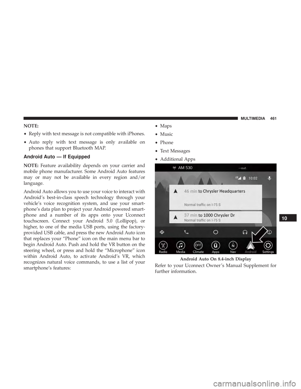
Android Auto allows you to use your voice to interact with
Android’s best-in-class speech technology through your
vehicle’s voice recognition system, and use your smart-
phone’s data plan to project your Android powered smart-
phone and a number of its apps onto your Uconnect
touchscreen. Connect your Android 5.0 (Lollipop), or
higher, to one of the media USB ports, using the factory-
provided USB cable, and press the new Android Auto icon
that replaces your “Phone” icon on the main menu bar to
begin Android Auto. Push and hold the VR button on the
steering wheel, or press and hold the “Microphone” icon
within Android Auto, to activate Android’s VR, which
recognizes natural voice commands, to use a list of your
smartphone’s features: •
Maps
• Music
• Phone
• Text Messages
• Additional Apps
Refer to your Uconnect Owner ’s Manual Supplement for
further information.
Android Auto On 8.4-inch Display
10
MULTIMEDIA 461