2018 CHEVROLET MALIBU clock
[x] Cancel search: clockPage 197 of 413
Chevrolet Malibu Owner Manual (GMNA-Localizing-U.S./Canada/Mexico-
11348460) - 2018 - crc - 5/3/17
196 Climate Controls
Climate Controls
Climate Control Systems
Climate Control Systems . . . . . 196
Dual Automatic ClimateControl System . . . . . . . . . . . . . 199
Air Vents
Air Vents . . . . . . . . . . . . . . . . . . . . . 203
Maintenance
Passenger Compartment AirFilter . . . . . . . . . . . . . . . . . . . . . . . . 203
Service . . . . . . . . . . . . . . . . . . . . . . . 204
Climate Control Systems
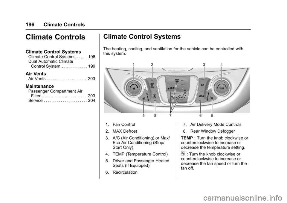
The heating, cooling, and ventilation for the vehicle can be controlled with
this system.
1. Fan Control
2. MAX Defrost
3. A/C (Air Conditioning) or Max/
Eco Air Conditioning (Stop/
Start Only)
4. TEMP (Temperature Control)
5. Driver and Passenger Heated Seats (If Equipped)
6. Recirculation 7. Air Delivery Mode Controls
8. Rear Window Defogger
TEMP : Turn the knob clockwise or
counterclockwise to increase or
decrease the temperature setting.
^: Turn the knob clockwise or
counterclockwise to increase or
decrease the fan speed or turn the
fan off.
Page 201 of 413
Chevrolet Malibu Owner Manual (GMNA-Localizing-U.S./Canada/Mexico-
11348460) - 2018 - crc - 5/3/17
200 Climate Controls
Press@to manually select
recirculation and the indicator light
will turn on. Press it again to select
outside air and the indicator light will
turn off.
Driver and Passenger
Temperature Controls : The
temperature can be adjusted
separately for the driver and the
passenger. Turn the knob clockwise
or counterclockwise to increase or
decrease the driver or passenger
temperature setting.
SYNC : Press to link the passenger
temperature settings to the driver
setting. The SYNC indicator light will
turn on. When the passenger
settings are adjusted, the SYNC
indicator light turns off.
Manual Operation
O: Press to turn the fan off or on.
If on is selected, or any other button
is pressed or knob turned, the
climate control system will turn on
and return to delivering airflow as
set. The temperature control and air
delivery mode can still be adjusted.
^: Press the large fan symbol to
increase the fan speed. Press the
small fan symbol to decrease the
fan speed. The fan speed setting
appears on the main display. When
the fan speed is decreased
completely, the fan turns off.
Pressing either button cancels
automatic fan control and the fan is
controlled manually. Press AUTO to
return to automatic operation.
Air Delivery Mode Controls :
Press
0,d, orcto change
the direction of the airflow. Any
combination of the three buttons
can be selected. The indicator light
in the button will turn on. The
current mode appears in the display
screen. Pressing any button cancels
automatic air delivery control and
the direction of the airflow is
controlled manually. Press AUTO to
return to automatic operation.
To change the current mode, select
one or more of the following modes:
0: Clears the windows of fog or
moisture. Air is directed to the
windshield.
d: Air is directed to the instrument
panel outlets.
c: Air is directed to the floor
outlets.
0MAX : Air is directed to the
windshield, the fan runs at a higher
speed, and the temperature of the
air is increased if not already at
maximum. This mode overrides the
previous mode selected and clears
fog or frost from the windshield
more quickly. When the button is
pressed again, the system returns
to the previous mode setting and
fan speed.
For best results, clear all snow and
ice from the windshield before
defrosting.
A/C : Press to turn the air
conditioning system on or off. If the
fan control is turned off or the
outside temperature falls below
freezing, the air conditioner will
not run.
Pressing this button cancels
automatic air conditioning and turns
off the air conditioner. Press AUTO
to return to automatic operation and
Page 287 of 413
Chevrolet Malibu Owner Manual (GMNA-Localizing-U.S./Canada/Mexico-
11348460) - 2018 - crc - 5/3/17
286 Vehicle Care
{Warning
Steam and scalding liquids from a
hot cooling system are under
pressure. Turning the pressure
cap, even a little, can cause them
to come out at high speed and
you could be burned. Never turn
the cap when the cooling system,
including the pressure cap, is hot.
Wait for the cooling system and
pressure cap to cool.
Caution
Failure to follow the specific
coolant fill procedure could cause
the engine to overheat and could
cause system damage. If coolant
is not visible in the surge tank,
contact your dealer.
The coolant surge tank pressure
cap can be removed when the
cooling system, including the surge
tank pressure cap and upper
radiator hose, is no longer hot.
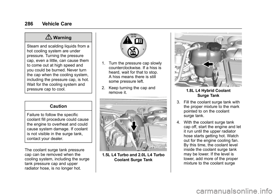
1. Turn the pressure cap slowly counterclockwise. If a hiss is
heard, wait for that to stop.
A hiss means there is still
some pressure left.
2. Keep turning the cap and remove it.
1.5L L4 Turbo and 2.0L L4 Turbo
Coolant Surge Tank
1.8L L4 Hybrid CoolantSurge Tank
3. Fill the coolant surge tank with the proper mixture to the mark
pointed to on the coolant
surge tank.
4. With the coolant surge tank cap off, start the engine and let
it run until the upper radiator
hose starts getting hot. Watch
out for the engine cooling fan.
By this time, the coolant level
inside the coolant surge tank
may be lower. If the level is
lower, add more of the proper
mixture to the coolant surge
Page 298 of 413
Chevrolet Malibu Owner Manual (GMNA-Localizing-U.S./Canada/Mexico-
11348460) - 2018 - crc - 5/3/17
Vehicle Care 297
Headlamps, Front Turn
Signal, Sidemarker, and
Parking Lamps
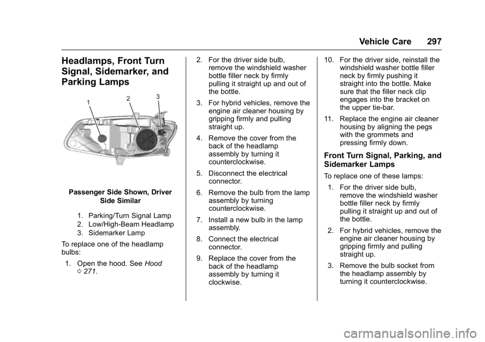
Passenger Side Shown, DriverSide Similar
1. Parking/Turn Signal Lamp
2. Low/High-Beam Headlamp
3. Sidemarker Lamp
To replace one of the headlamp
bulbs:
1. Open the hood. See Hood
0 271. 2. For the driver side bulb,
remove the windshield washer
bottle filler neck by firmly
pulling it straight up and out of
the bottle.
3. For hybrid vehicles, remove the engine air cleaner housing by
gripping firmly and pulling
straight up.
4. Remove the cover from the back of the headlamp
assembly by turning it
counterclockwise.
5. Disconnect the electrical connector.
6. Remove the bulb from the lamp assembly by turning
counterclockwise.
7. Install a new bulb in the lamp assembly.
8. Connect the electrical connector.
9. Replace the cover from the back of the headlamp
assembly by turning it
clockwise. 10. For the driver side, reinstall the
windshield washer bottle filler
neck by firmly pushing it
straight into the bottle. Make
sure that the filler neck clip
engages into the bracket on
the upper tie-bar.
11. Replace the engine air cleaner housing by aligning the pegs
with the grommets and
pressing firmly down.
Front Turn Signal, Parking, and
Sidemarker Lamps
To replace one of these lamps:
1. For the driver side bulb, remove the windshield washer
bottle filler neck by firmly
pulling it straight up and out of
the bottle.
2. For hybrid vehicles, remove the engine air cleaner housing by
gripping firmly and pulling
straight up.
3. Remove the bulb socket from the headlamp assembly by
turning it counterclockwise.
Page 299 of 413
Chevrolet Malibu Owner Manual (GMNA-Localizing-U.S./Canada/Mexico-
11348460) - 2018 - crc - 5/3/17
298 Vehicle Care
4. Remove the bulb from thesocket.
5. Replace the bulb in the bulb socket.
6. Install the bulb socket in the headlamp assembly by turning
it clockwise.
7. For the driver side, reinstall the windshield washer bottle filler
neck by firmly pushing it
straight into the bottle. Make
sure that the filler neck clip
engages into the bracket on
the upper tie-bar.
8. Replace the engine air cleaner housing by aligning the pegs
with the grommets and
pressing firmly down.Taillamps, Turn Signal,
Stoplamps, and Back-Up
Lamps (LS and LT)
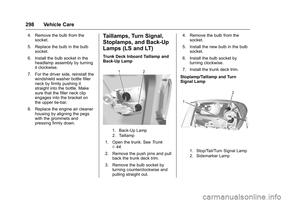
Trunk Deck Inboard Taillamp and
Back-Up Lamp
1. Back-Up Lamp
2. Taillamp
1. Open the trunk. See Trunk
0 44.
2. Remove the push pins and pull back the trunk deck trim.
3. Remove the bulb socket by turning counterclockwise and
pulling straight out. 4. Remove the bulb from the
socket.
5. Install the new bulb in the bulb socket.
6. Install the bulb socket by turning clockwise.
7. Install the trunk deck trim.
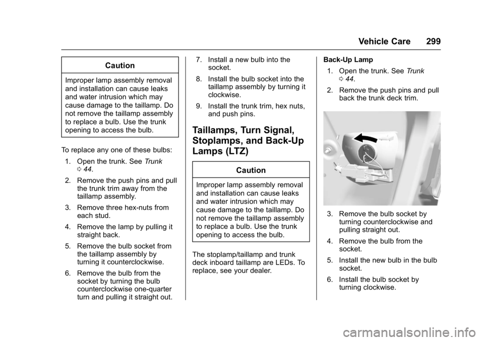
Stoplamp/Taillamp and Turn
Signal Lamp
1. Stop/Tail/Turn Signal Lamp
2. Sidemarker Lamp
Page 300 of 413
Chevrolet Malibu Owner Manual (GMNA-Localizing-U.S./Canada/Mexico-
11348460) - 2018 - crc - 5/3/17
Vehicle Care 299
Caution
Improper lamp assembly removal
and installation can cause leaks
and water intrusion which may
cause damage to the taillamp. Do
not remove the taillamp assembly
to replace a bulb. Use the trunk
opening to access the bulb.
To replace any one of these bulbs: 1. Open the trunk. See Trunk
0 44.
2. Remove the push pins and pull the trunk trim away from the
taillamp assembly.
3. Remove three hex-nuts from each stud.
4. Remove the lamp by pulling it straight back.
5. Remove the bulb socket from the taillamp assembly by
turning it counterclockwise.
6. Remove the bulb from the socket by turning the bulb
counterclockwise one-quarter
turn and pulling it straight out. 7. Install a new bulb into the
socket.
8. Install the bulb socket into the taillamp assembly by turning it
clockwise.
9. Install the trunk trim, hex nuts, and push pins.
Taillamps, Turn Signal,
Stoplamps, and Back-Up
Lamps (LTZ)
Caution
Improper lamp assembly removal
and installation can cause leaks
and water intrusion which may
cause damage to the taillamp. Do
not remove the taillamp assembly
to replace a bulb. Use the trunk
opening to access the bulb.
The stoplamp/taillamp and trunk
deck inboard taillamp are LEDs. To
replace, see your dealer. Back-Up Lamp
1. Open the trunk. See Trunk
0 44.
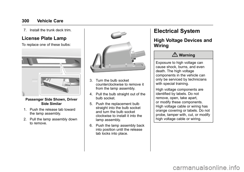
2. Remove the push pins and pull back the trunk deck trim.
3. Remove the bulb socket byturning counterclockwise and
pulling straight out.
4. Remove the bulb from the socket.
5. Install the new bulb in the bulb socket.
6. Install the bulb socket by turning clockwise.
Page 301 of 413
Chevrolet Malibu Owner Manual (GMNA-Localizing-U.S./Canada/Mexico-
11348460) - 2018 - crc - 5/3/17
300 Vehicle Care
7. Install the trunk deck trim.
License Plate Lamp
To replace one of these bulbs:
Passenger Side Shown, DriverSide Similar
1. Push the release tab toward the lamp assembly.
2. Pull the lamp assembly down to remove.
3. Turn the bulb socketcounterclockwise to remove it
from the lamp assembly.
4. Pull the bulb straight out of the bulb socket.
5. Push the replacement bulb straight into the bulb socket
and turn the bulb socket
clockwise to install it into the
lamp assembly.
6. Push the lamp assembly back into position until the release
tab locks into place.
Electrical System
High Voltage Devices and
Wiring
{Warning
Exposure to high voltage can
cause shock, burns, and even
death. The high voltage
components in the vehicle can
only be serviced by technicians
with special training.
High voltage components are
identified by labels. Do not
remove, open, take apart,
or modify these components.
High voltage cable or wiring has
orange covering or labels. Do not
probe, tamper with, cut, or modify
high voltage cable or wiring.
Page 333 of 413
Chevrolet Malibu Owner Manual (GMNA-Localizing-U.S./Canada/Mexico-
11348460) - 2018 - crc - 5/3/17
332 Vehicle Care
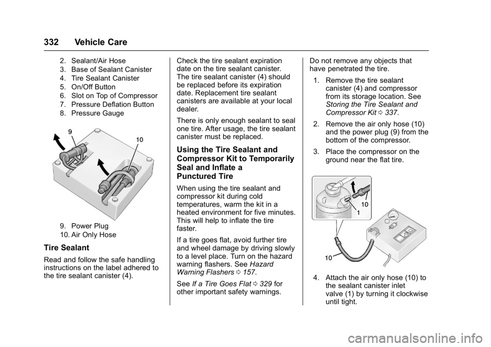
2. Sealant/Air Hose
3. Base of Sealant Canister
4. Tire Sealant Canister
5. On/Off Button
6. Slot on Top of Compressor
7. Pressure Deflation Button
8. Pressure Gauge
9. Power Plug
10. Air Only Hose
Tire Sealant
Read and follow the safe handling
instructions on the label adhered to
the tire sealant canister (4).Check the tire sealant expiration
date on the tire sealant canister.
The tire sealant canister (4) should
be replaced before its expiration
date. Replacement tire sealant
canisters are available at your local
dealer.
There is only enough sealant to seal
one tire. After usage, the tire sealant
canister must be replaced.
Using the Tire Sealant and
Compressor Kit to Temporarily
Seal and Inflate a
Punctured Tire
When using the tire sealant and
compressor kit during cold
temperatures, warm the kit in a
heated environment for five minutes.
This will help to inflate the tire
faster.
If a tire goes flat, avoid further tire
and wheel damage by driving slowly
to a level place. Turn on the hazard
warning flashers. See
Hazard
Warning Flashers 0157.
See If a Tire Goes Flat 0329 for
other important safety warnings. Do not remove any objects that
have penetrated the tire.
1. Remove the tire sealant canister (4) and compressor
from its storage location. See
Storing the Tire Sealant and
Compressor Kit 0337.
2. Remove the air only hose (10) and the power plug (9) from the
bottom of the compressor.
3. Place the compressor on the ground near the flat tire.
4. Attach the air only hose (10) tothe sealant canister inlet
valve (1) by turning it clockwise
until tight.