2018 Alfa Romeo Stelvio Warning symbols
[x] Cancel search: Warning symbolsPage 8 of 276

HOW TO USE THIS MANUAL
Operating Instructions
Each time an instruction is given that concerns direction (left/right or forward/backward), it is written to be read from the
perspective of an occupant in the driver's seat. If a direction is written from a different perspective, it will be specified as such in the
text as appropriate.
The figures in the manual are only examples: this might imply that some details of the image do not correspond to the actual
arrangement of your vehicle.
To identify the chapter with the information necessary, you can consult the index at the end of this manual.
Chapters can be rapidly identified with dedicated graphic tabs, located at the side of each odd page. There is also a key for getting to
know the chapter order and the relevant symbols in the tabs. Additionally, there is a textual indication of each current chapter at the
side of each even page.
Warnings And Cautions
While reading this Owner’s Manual you will find a series ofWARNINGSthat must be carefully followed to prevent incorrect use of the
components of the vehicle, which could cause accidents or injuries.
There are also CAUTIONSto prevent procedures that could damage your vehicle.
Therefore all WARNINGSandCAUTIONS must always be carefully followed.
WARNINGS andCAUTIONS are recalled in the text with the following symbols:
Personal Safety:
Vehicle Safety:
Note: This Owner’s Manual describes all vehicle models. Optional equipment meant for specific markets or particular models
are not identified as such in the text: you need to consider only the information related to the model you own. Any content
introduced throughout the production of the model, outside the specific request of options at the time of purchase, will be
identified by the indicator: — if equipped.
The data contained in this publication is intended to help you use your vehicle in the best possible way. FCA US LLC aims for
constant improvement of the vehicles produced. For this reason, it reserves the right to make changes to the model described
for technical and/or commercial reasons.
For further information, contact your authorized dealer.
Page 9 of 276

Symbols
Some vehicle components have colored labels with symbols indicating precautions to be observed when using this component. It is
important to follow all warnings when operating your vehicle. See below for a brief description of each symbol.
READ THE OWNER
HANDBOOKDO NOT TOUCH WITH
HANDSCOMPONENT CAN START
AUTOMATICALLY ALSO
WHEN ENGINE IS OFF
PROTECT YOUR EYESDO NOT OPEN THE CAP
WHEN THE ENGINE IS
HOTDO NOT OPEN: HIGH
PRESSURE GAS
KEEP CHILDREN AT A
DISTANCEBURSTINGMOVING PARTS KEEP PARTS
OF YOUR BODY AND
CLOTHES AWAY
DO NOT APPROACH
FLAMESCORROSIVE LIQUIDHIGH VOLTAGE
Page 77 of 276

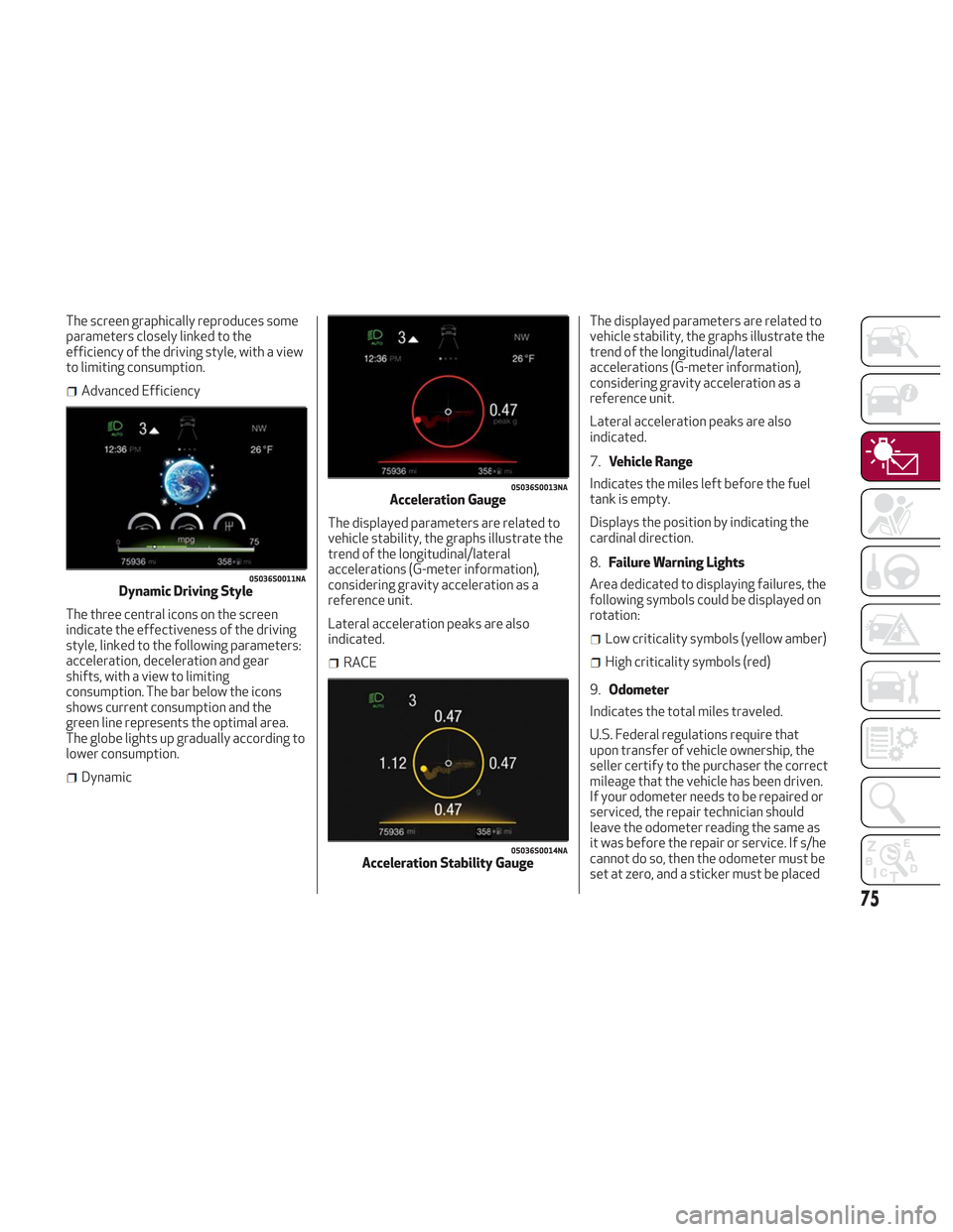
The screen graphically reproduces some
parameters closely linked to the
efficiency of the driving style, with a view
to limiting consumption.
Advanced Efficiency
The three central icons on the screen
indicate the effectiveness of the driving
style, linked to the following parameters:
acceleration, deceleration and gear
shifts, with a view to limiting
consumption. The bar below the icons
shows current consumption and the
green line represents the optimal area.
The globe lights up gradually according to
lower consumption.
Dynamic The displayed parameters are related to
vehicle stability, the graphs illustrate the
trend of the longitudinal/lateral
accelerations (G-meter information),
considering gravity acceleration as a
reference unit.
Lateral acceleration peaks are also
indicated.
RACEThe displayed parameters are related to
vehicle stability, the graphs illustrate the
trend of the longitudinal/lateral
accelerations (G-meter information),
considering gravity acceleration as a
reference unit.
Lateral acceleration peaks are also
indicated.
7.
Vehicle Range
Indicates the miles left before the fuel
tank is empty.
Displays the position by indicating the
cardinal direction.
8. Failure Warning Lights
Area dedicated to displaying failures, the
following symbols could be displayed on
rotation:
Low criticality symbols (yellow amber)
High criticality symbols (red)
9. Odometer
Indicates the total miles traveled.
U.S. Federal regulations require that
upon transfer of vehicle ownership, the
seller certify to the purchaser the correct
mileage that the vehicle has been driven.
If your odometer needs to be repaired or
serviced, the repair technician should
leave the odometer reading the same as
it was before the repair or service. If s/he
cannot do so, then the odometer must be
set at zero, and a sticker must be placed
05036S0011NADynamic Driving Style
05036S0013NAAcceleration Gauge
05036S0014NAAcceleration Stability Gauge
75
Page 88 of 276

Blue Telltale Indicator Light
Indicator LightWhat It Means What To Do
HIGH BEAM HEADLIGHTS
This indicator shows that the high beam headlights are on.
Push the multifunction control lever away from you to
switch the headlights to high beam. Push the lever a
second time to switch the headlights back to low beam.
Pull the lever toward you for a temporary high beam on,
“flash to pass” scenario.
Red Symbols
Warning LightWhat It Means What To Do
LOW ENGINE OIL PRESSURE
This telltale indicates low engine oil pressure. If the
telltale turns on while driving, stop the vehicle and shut
off the engine as soon as possible. A chime will sound
when this telltale turns on. Do not operate the vehicle
until the cause is corrected. This telltale does not indicate
how much oil is in the engine.
Note:Do not use the vehicle until the failure has been solved.
The illumination of the telltale does not indicate the
amount of oil in the engine: the oil level can be checked on
the display upon entering the vehicle and also by
activating the "Oil level" function on the Information and
Entertainment System.Contact an authorized dealer as soon as possible.
86
GETTING TO KNOW YOUR INSTRUMENT PANEL
Page 93 of 276

Amber Symbols
Warning LightsWhat It Means What To Do
ENGINE IMMOBILIZER FAILURE / BREAK-IN ATTEMPT
Engine Immobilizer System Failure
The telltale will illuminate to report a failure of the Engine
Immobilizer system. Contact an authorized dealer as soon as possible.
Break-In Attempt
The telltale will illuminate when the ignition is cycled to
ON position, to indicate a possible break-in attempt
detected by the alarm system.
Electronic Key Not Recognized
The telltale will illuminate when the engine is started and
the electronic key is not recognized by the system.
Alarm System Failure
The telltale will illuminate to report an alarm system
failure.
FUEL CUT-OFF INDICATOR LIGHT
The telltale will illuminate after an accident has occurred
and the system has shut the fuel off. For reactivating the fuel cut-off system, refer to
“Enhanced Accident Response System” in “Occupant
Restraint Systems" in "Safety” for further information. If it
is not possible to restore the fuel supply, contact an
authorized dealer.
PARK SENSORS SYSTEM FAILURE
The telltale will illuminate when the system has failed or is
not available.
Contact an authorized dealer to have the system checked.
POSSIBLE ICE ON ROAD
The telltale will illuminate when the outside temperature
falls to or below 37°F (3°C).Drive carefully during icy conditions.
91
Page 179 of 276

There are suitable visibility conditions.
The road is straight or with wide radius
bends.
A suitable distance is kept from the
vehicle in front.
The turn signal is not active.
Symbols And Messages On The Display
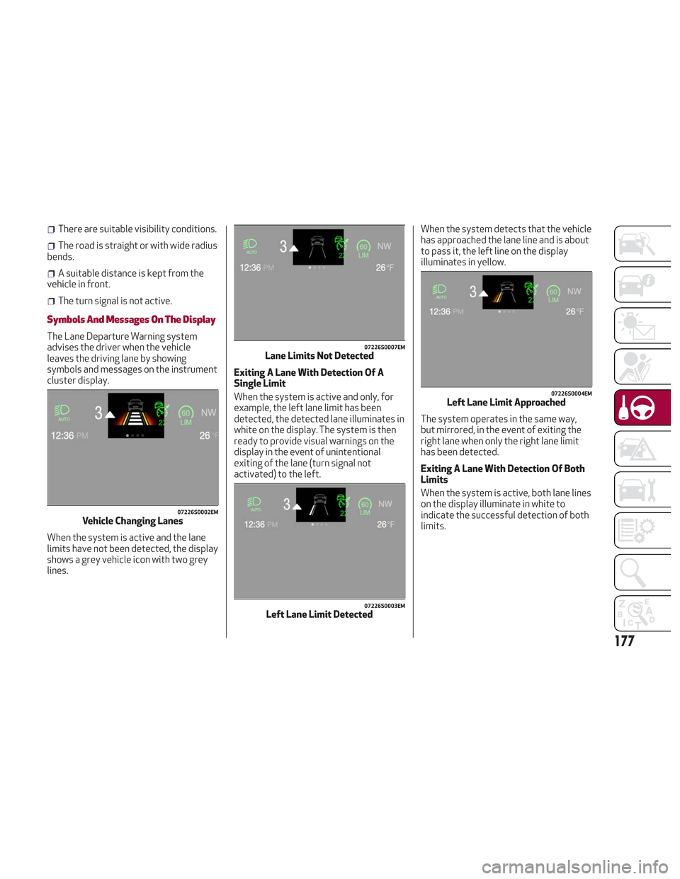
The Lane Departure Warning system
advises the driver when the vehicle
leaves the driving lane by showing
symbols and messages on the instrument
cluster display.
When the system is active and the lane
limits have not been detected, the display
shows a grey vehicle icon with two grey
lines. Exiting A Lane With Detection Of A
Single Limit
When the system is active and only, for
example, the left lane limit has been
detected, the detected lane illuminates in
white on the display. The system is then
ready to provide visual warnings on the
display in the event of unintentional
exiting of the lane (turn signal not
activated) to the left.When the system detects that the vehicle
has approached the lane line and is about
to pass it, the left line on the display
illuminates in yellow.
The system operates in the same way,
but mirrored, in the event of exiting the
right lane when only the right lane limit
has been detected.
Exiting A Lane With Detection Of Both
Limits
When the system is active, both lane lines
on the display illuminate in white to
indicate the successful detection of both
limits.
07226S0002EMVehicle Changing Lanes
07226S0007EMLane Limits Not Detected
07226S0003EMLeft Lane Limit Detected
07226S0004EMLeft Lane Limit Approached
177
Page 181 of 276

REAR BACK-UP CAMERA /
DYNAMIC GRIDLINES
Description
The Rear Back-Up Camera is located on
the liftgate, above the rear license plate.
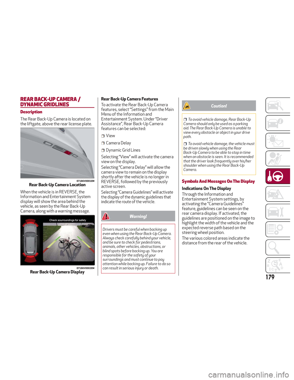
When the vehicle is in REVERSE, the
Information and Entertainment System
display will show the area behind the
vehicle, as seen by the Rear Back-Up
Camera, along with a warning message.Rear Back-Up Camera Features
To activate the Rear Back-Up Camera
features, select “Settings” from the Main
Menu of the Information and
Entertainment System. Under “Driver
Assistance”, Rear Back-Up Camera
features can be selected:
View
Camera Delay
Dynamic Grid Lines
Selecting “View” will activate the camera
view on the display.
Selecting “Camera Delay” will allow the
camera view to remain on the display
shortly after the vehicle is no longer in
REVERSE, followed by the previously
active screen.
Selecting “Camera Guidelines” will activate
the display of the dynamic guidelines that
indicate the route of the vehicle.
Warning!
Drivers must be careful when backing up
even when using the Rear Back-Up Camera.
Always check carefully behind your vehicle,
and be sure to check for pedestrians,
animals, other vehicles, obstructions, or
blind spots before backing up. You are
responsible for the safety of your
surroundings and must continue to pay
attention while backing up. Failure to do so
can result in serious injury or death.
Caution!
To avoid vehicle damage, Rear Back-Up
Camera should only be used as a parking
aid. The Rear Back-Up Camera is unable to
view every obstacle or object in your drive
path.
To avoid vehicle damage, the vehicle must
be driven slowly when using the Rear
Back-Up Camera to be able to stop in time
when an obstacle is seen. It is recommended
that the driver look frequently over his/her
shoulder when using the Rear Back-Up
Camera.
Symbols And Messages On The Display
Indications On The Display
Through the Information and
Entertainment System settings, by
activating the "Camera Guidelines"
feature, guidelines can be seen on the
rear camera display. If activated, the
guidelines are positioned on the image to
highlight the width of the vehicle and the
expected reverse path based on the
steering wheel position.
The various colored areas indicate the
distance from the rear of the vehicle.
07186V0001EMRear Back-Up Camera Location
07186V0002EMRear Back-Up Camera Display
179