2018 Alfa Romeo Stelvio Forward Collision
[x] Cancel search: Forward CollisionPage 36 of 276
HEAD RESTRAINTS
Head restraints are designed to reduce
the risk of injury by restricting head
movement in the event of a rear impact.
Head restraints should be adjusted so
that the top of the head restraint is
located above the top of your ear.
Warning!
A loose head restraint thrown forward in
a collision or hard stop could cause serious
injury or death to occupants of the vehicle.
Always securely stow removed head
restraints in a location outside the occupant
compartment.
ALL the head restraints MUST be
reinstalled in the vehicle to properly protect
the occupants. Follow the re-installation
instructions above prior to operating the
vehicle or occupying a seat.
Do not place items over the top of the
Reactive Head Restraint, such as coats,
seat covers or portable DVD players. These
items may interfere with the operation of
the Reactive Head Restraint in the event of
a collision and could result in serious injury
or death.
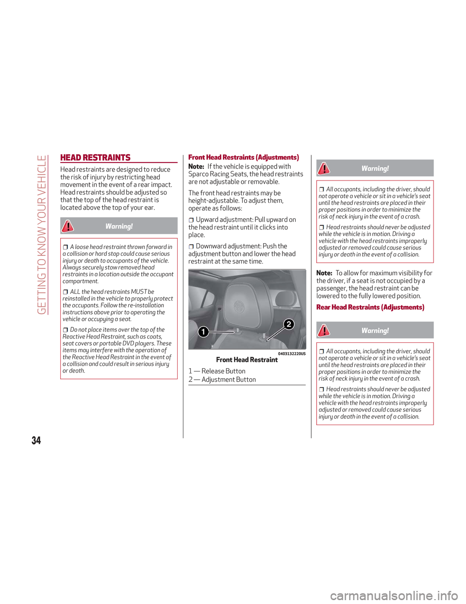
Front Head Restraints (Adjustments)
Note: If the vehicle is equipped with
Sparco Racing Seats, the head restraints
are not adjustable or removable.
The front head restraints may be
height-adjustable. To adjust them,
operate as follows:
Upward adjustment: Pull upward on
the head restraint until it clicks into
place.
Downward adjustment: Push the
adjustment button and lower the head
restraint at the same time.
Warning!
All occupants, including the driver, should
not operate a vehicle or sit in a vehicle’s seat
until the head restraints are placed in their
proper positions in order to minimize the
risk of neck injury in the event of a crash.
Head restraints should never be adjusted
while the vehicle is in motion. Driving a
vehicle with the head restraints improperly
adjusted or removed could cause serious
injury or death in the event of a collision.
Note: To allow for maximum visibility for
the driver, if a seat is not occupied by a
passenger, the head restraint can be
lowered to the fully lowered position.
Rear Head Restraints (Adjustments)
Warning!
All occupants, including the driver, should
not operate a vehicle or sit in a vehicle’s seat
until the head restraints are placed in their
proper positions in order to minimize the
risk of neck injury in the event of a crash.
Head restraints should never be adjusted
while the vehicle is in motion. Driving a
vehicle with the head restraints improperly
adjusted or removed could cause serious
injury or death in the event of a collision.
0403132220USFront Head Restraint
1 — Release Button
2 — Adjustment Button
34
GETTING TO KNOW YOUR VEHICLE
Page 37 of 276
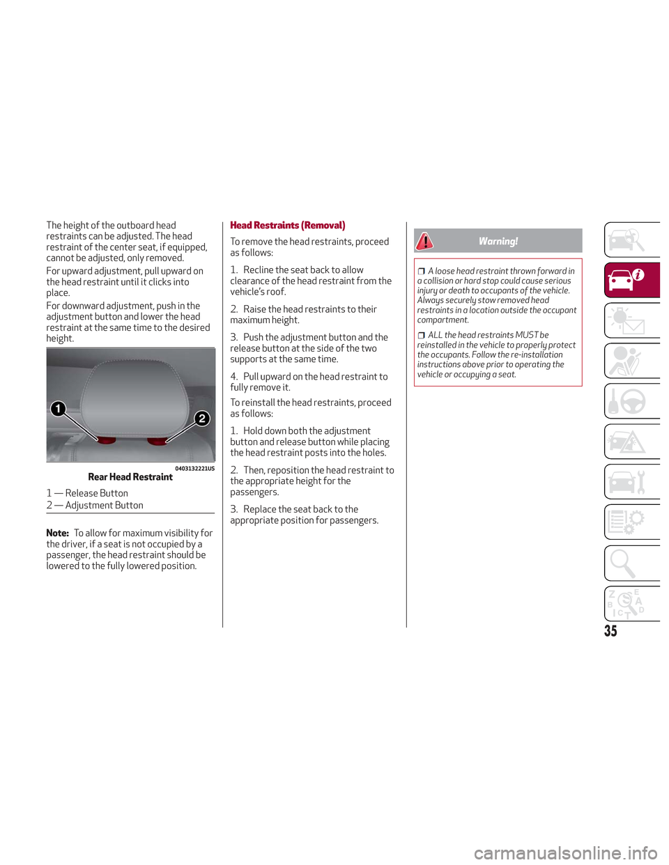
The height of the outboard head
restraints can be adjusted. The head
restraint of the center seat, if equipped,
cannot be adjusted, only removed.
For upward adjustment, pull upward on
the head restraint until it clicks into
place.
For downward adjustment, push in the
adjustment button and lower the head
restraint at the same time to the desired
height.
Note:To allow for maximum visibility for
the driver, if a seat is not occupied by a
passenger, the head restraint should be
lowered to the fully lowered position.Head Restraints (Removal)
To remove the head restraints, proceed
as follows:
1. Recline the seat back to allow
clearance of the head restraint from the
vehicle’s roof.
2. Raise the head restraints to their
maximum height.
3. Push the adjustment button and the
release button at the side of the two
supports at the same time.
4. Pull upward on the head restraint to
fully remove it.
To reinstall the head restraints, proceed
as follows:
1. Hold down both the adjustment
button and release button while placing
the head restraint posts into the holes.
2. Then, reposition the head restraint to
the appropriate height for the
passengers.
3. Replace the seat back to the
appropriate position for passengers.Warning!
A loose head restraint thrown forward in
a collision or hard stop could cause serious
injury or death to occupants of the vehicle.
Always securely stow removed head
restraints in a location outside the occupant
compartment.
ALL the head restraints MUST be
reinstalled in the vehicle to properly protect
the occupants. Follow the re-installation
instructions above prior to operating the
vehicle or occupying a seat.
0403132221USRear Head Restraint
1 — Release Button
2 — Adjustment Button
35
Page 63 of 276
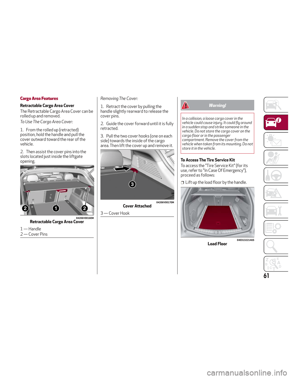
Cargo Area Features
Retractable Cargo Area Cover
The Retractable Cargo Area Cover can be
rolled up and removed.
To Use The Cargo Area Cover:
1. From the rolled up (retracted)
position, hold the handle and pull the
cover outward toward the rear of the
vehicle.
2. Then assist the cover pins into the
slots located just inside the liftgate
opening.Removing The Cover:
1. Retract the cover by pulling the
handle slightly rearward to release the
cover pins.
2. Guide the cover forward until it is fully
retracted.
3. Pull the two cover hooks (one on each
side) towards the inside of the cargo
area. Then lift the cover up and remove it.Warning!
In a collision, a loose cargo cover in the
vehicle could cause injury. It could fly around
in a sudden stop and strike someone in the
vehicle. Do not store the cargo cover on the
cargo floor or in the passenger
compartment. Remove the cover from the
vehicle when taken from its mounting. Do not
store it in the vehicle.
To Access The Tire Service Kit
To access the "Tire Service Kit" (for its
use, refer to "In Case Of Emergency"),
proceed as follows:
Lift up the load floor by the handle.
04206V0016EMRetractable Cargo Area Cover
1 — Handle
2 — Cover Pins
04206V0017EMCover Attached
3 — Cover Hook
0403132214USLoad Floor
61
Page 69 of 276
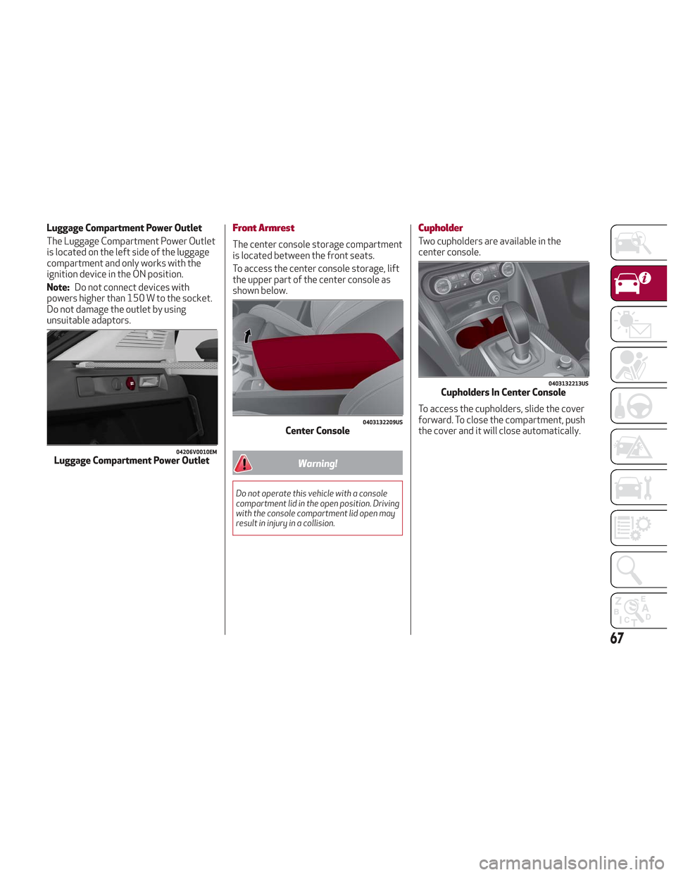
Luggage Compartment Power Outlet
The Luggage Compartment Power Outlet
is located on the left side of the luggage
compartment and only works with the
ignition device in the ON position.
Note:Do not connect devices with
powers higher than 150 W to the socket.
Do not damage the outlet by using
unsuitable adaptors.Front Armrest
The center console storage compartment
is located between the front seats.
To access the center console storage, lift
the upper part of the center console as
shown below.
Warning!
Do not operate this vehicle with a console
compartment lid in the open position. Driving
with the console compartment lid open may
result in injury in a collision.
Cupholder
Two cupholders are available in the
center console.
To access the cupholders, slide the cover
forward. To close the compartment, push
the cover and it will close automatically.
04206V0010EMLuggage Compartment Power Outlet
0403132209USCenter Console
0403132213USCupholders In Center Console
67
Page 75 of 276

Reconfigurable Display Items
1.Headlight Warning Lights
Displays the headlight warning light for
either of the following active modes:
Headlights
Automatic Headlights
2. Gear Selector Information
Displays the following information
controlled by the gear selector function:
P = PARK
R = REVERSE
N = NEUTRAL
D= DRIVE, (automatic forward speed)
AutoStick: + shifting to higher gear in
manual (sequential) driving mode –
shifting to lower gear in sequential
driving mode
3. Forward Collision, Lane Departure,
Cruise Control
Displays operations for the following
modes:
Forward Collision Warning (FCW)
Lane Departure Warning (LDW)
Cruise Control (CC) or Active Cruise
Control (ACC) (if equipped) 4.
Speed Limit Warning Light
Shows information regarding the Speed
Limiter function.
5. Compass
6. Reconfigurable Main Area
Can display the following screens:
Home
Trip A
Trip B (can be activated/deactivated
through the Information and
Entertainment System)
Performance
The screens can be selected, on rotation,
by pushing the MENU selection button on
the windshield wiper stalk.
Depending on the driving mode chosen
using the Alfa DNA Pro (Dynamic, Natural,
Advanced Efficiency and RACE), the
screens can be graphically different. Navigation instructions and call
information can be set and displayed in
the Information and Entertainment
System.
Home
The parameters shown on the display for
the Dynamic, Natural and Advanced
Efficiency modes are:
Time
Outside Temperature
Current Speed (shown if the repeat
modes of the Phone and Navigation
functions are not active)
Range
05036V0002EMMENU Selection Button
05036S0004NAInstrument Cluster Display
73
Page 86 of 276
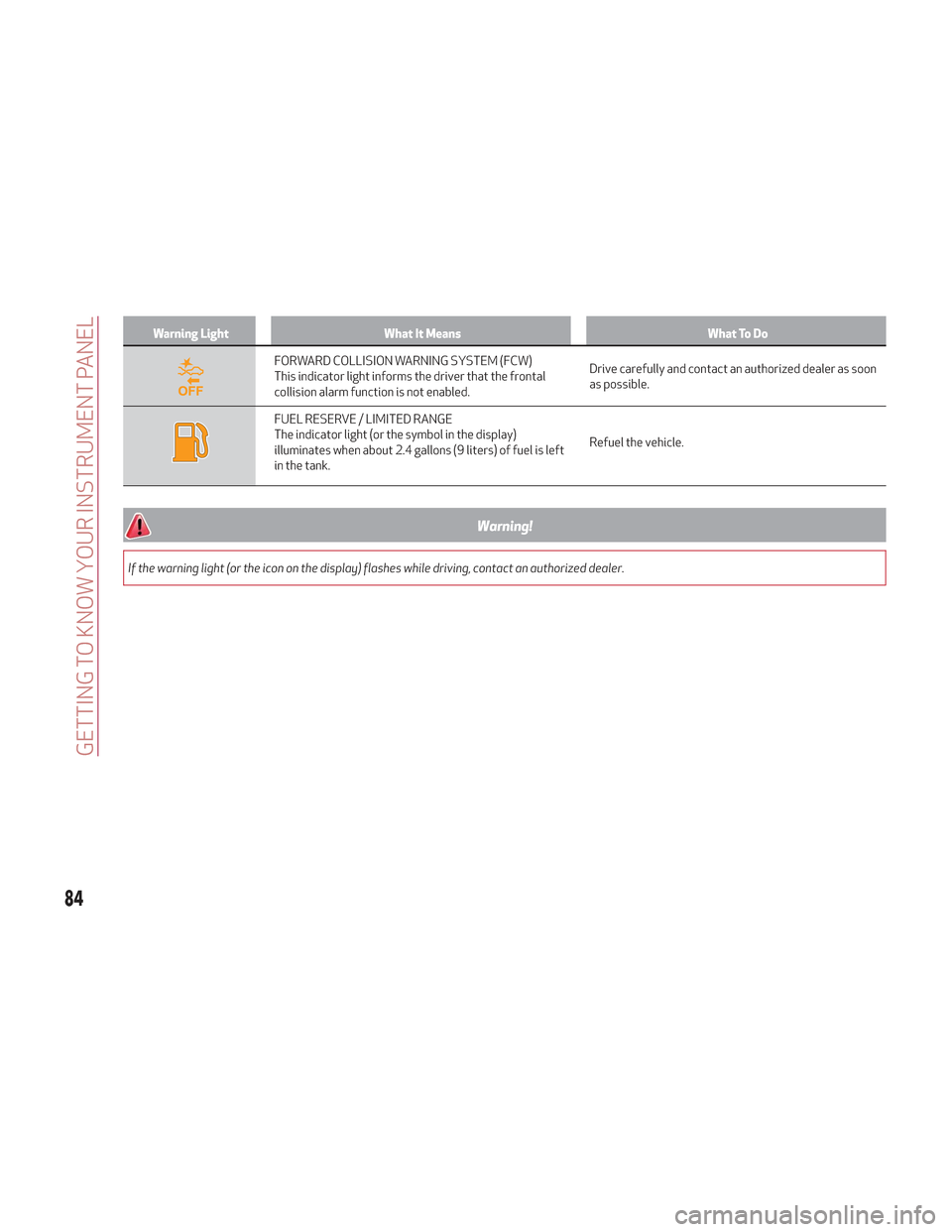
Warning LightWhat It Means What To Do
FORWARD COLLISION WARNING SYSTEM (FCW)
This indicator light informs the driver that the frontal
collision alarm function is not enabled.Drive carefully and contact an authorized dealer as soon
as possible.
FUEL RESERVE / LIMITED RANGE
The indicator light (or the symbol in the display)
illuminates when about 2.4 gallons (9 liters) of fuel is left
in the tank.Refuel the vehicle.
Warning!
If the warning light (or the icon on the display) flashes while driving, contact an authorized dealer.
84
GETTING TO KNOW YOUR INSTRUMENT PANEL
Page 95 of 276

Warning LightWhat It Means What To Do
FORWARD COLLISION WARNING (FCW) SYSTEM
FAILURE
The telltale will illuminate in the case of failure of the
Forward Collision Warning system.Contact an authorized dealer as soon as possible.
START & STOP SYSTEM FAILURE
This telltale will illuminate to report a Stop & Start
system failure.Contact an authorized dealer as soon as possible to have
the failure eliminated.
RAIN SENSOR FAILURE
The telltale will illuminate in the case of failure of the
automatic windshield wiper.
Contact an authorized dealer as soon as possible.
DUSK SENSOR FAILURE
The telltale will illuminate in the case of failure of the
automatic low beam alignment.Contact an authorized dealer as soon as possible.
BLIND SPOT MONITORING SYSTEM FAILURE
The telltale will illuminate in the event of a Blind Spot
Monitoring system failure.Contact an authorized dealer as soon as possible.
FUEL LEVEL SENSOR FAILURE
The telltale will illuminate in the event of fuel level sensor
failure.Contact an authorized dealer as soon as possible.
EXTERIOR LIGHTS FAILURE
The telltale will illuminate to indicate a failure on the
following lights: daytime running lights (DRLs) / parking
lights / trailer turn signal indicators (if present) / trailer
lights (if present) / side lights / turn signal indicators /
rear fog light / reversing light / brake lights / license plate
lights.The failure may be caused by a blown bulb, a blown
protection fuse, or an interruption of the electrical
connection.
Replace the bulb or the relevant fuse. Contact an
authorized dealer.
93
Page 109 of 276

Dynamic Steering Torque (DST) System
The DST function uses the integration of
the ESC system with the electric power
steering to increase the safety level of
the whole vehicle.
In critical situations for example (braking
on surfaces with different grip
conditions), the ESC system influences
the steering through the DST function to
implement an additional torque
contribution on the steering wheel in
order to suggest the most correct
maneuver to the driver.
The coordinated action of the brakes and
steering increases the safety and control
of the vehicle.
Note:The DST feature is only meant to
help the driver realize the correct course
of action through small torques on the
steering wheel, which means the
effectiveness of the DST feature is highly
dependent on the driver’s sensitivity and
overall reaction to the applied torque. It
is very important to realize that this
feature will not steer the vehicle,
meaning the driver is still responsible for
steering the vehicle.
Active Torque Vectoring (ATV) System
The dynamic drive control is used to
optimize and balance the drive torque
between the wheels of the same axles.
The ATV system improves the grip in
turns, sending more drive torque to the
external wheel.
Given that, in a turn, the external wheels
of the car travel more than the internal
ones and therefore turn faster, sending a
higher thrust to the external rear wheel
allows for the car to be more stable and
to not suffer an "understeer" condition.
Understeer occurs when the vehicle is
turning less than appropriate for the
steering wheel position.
AUXILIARY DRIVING SYSTEMS
The following auxiliary driving systems
are available in this vehicle:
Blind Spot Monitoring (BSM)
Forward Collision Warning Plus
(FCW+)
Tire Pressure Monitoring System
(TPMS)
Blind Spot Monitoring (BSM) System
The Blind Spot Monitoring (BSM) system
uses two radar sensors, located in the
rear bumper (one on each side), to detect
the presence of other vehicles in the rear
side blind spots of your vehicle.
The system warns the driver about the
presence of other vehicles in the
detection area by illuminating the
warning light located within the door
mirror on the side in which the other
vehicle was detected.
0403132303USRear Sensor Location
107