2018 Alfa Romeo Stelvio stop start
[x] Cancel search: stop startPage 201 of 276
Inflation Procedure
Warning!
Do not attempt to seal a tire on the side of
the vehicle closest to traffic. Pull far enough
off the road to avoid the danger of being hit
when using the Tire Service Kit.
Do not use Tire Service Kit or drive the
vehicle under the following circumstances:
If the puncture in the tire tread is
approximately 1/4 inch (6 mm) or larger.
If the tire has any sidewall damage.
If the tire has any damage from driving
with extremely low tire pressure.
If the tire has any damage from driving on
a flat tire.
If the wheel has any damage.
If you are unsure of the condition of the
tire or the wheel.
Keep Tire Service Kit away from open
flames or heat sources.
A loose Tire Service Kit thrown forward in
a collision or hard stop could endanger the
occupants of the vehicle. Always stow the
Tire Service Kit in the place provided. Failure
to follow these warnings can result in
injuries that are serious or fatal to you, your
passengers, and others around you.
Take care not to allow the contents of Tire
Service Kit to come in contact with hair,
eyes, or clothing. Tire Service Kit sealant is
harmful if inhaled, swallowed, or absorbed through the skin. It causes skin, eye, and
respiratory irritation. Flush immediately
with plenty of water if there is any contact
with eyes or skin. Change clothing as soon
as possible, if there is any contact with
clothing.
Tire Service Kit Sealant solution contains
latex. In case of an allergic reaction or rash,
consult a physician immediately. Keep Tire
Service Kit out of reach of children. If
swallowed, rinse mouth immediately with
plenty of water and drink plenty of water.
Do not induce vomiting! Consult a physician
immediately.
To use the Tire Service Kit, proceed as
follows:
1. Apply the electric park brake.
2. Connect the hose to the sealant
cartridge containing the sealing liquid.
Unscrew the tire valve cap, take out the
filler tube and tighten the fitting on the
tire valve. 3. Make sure the power switch of the
compressor is in the off position (O).
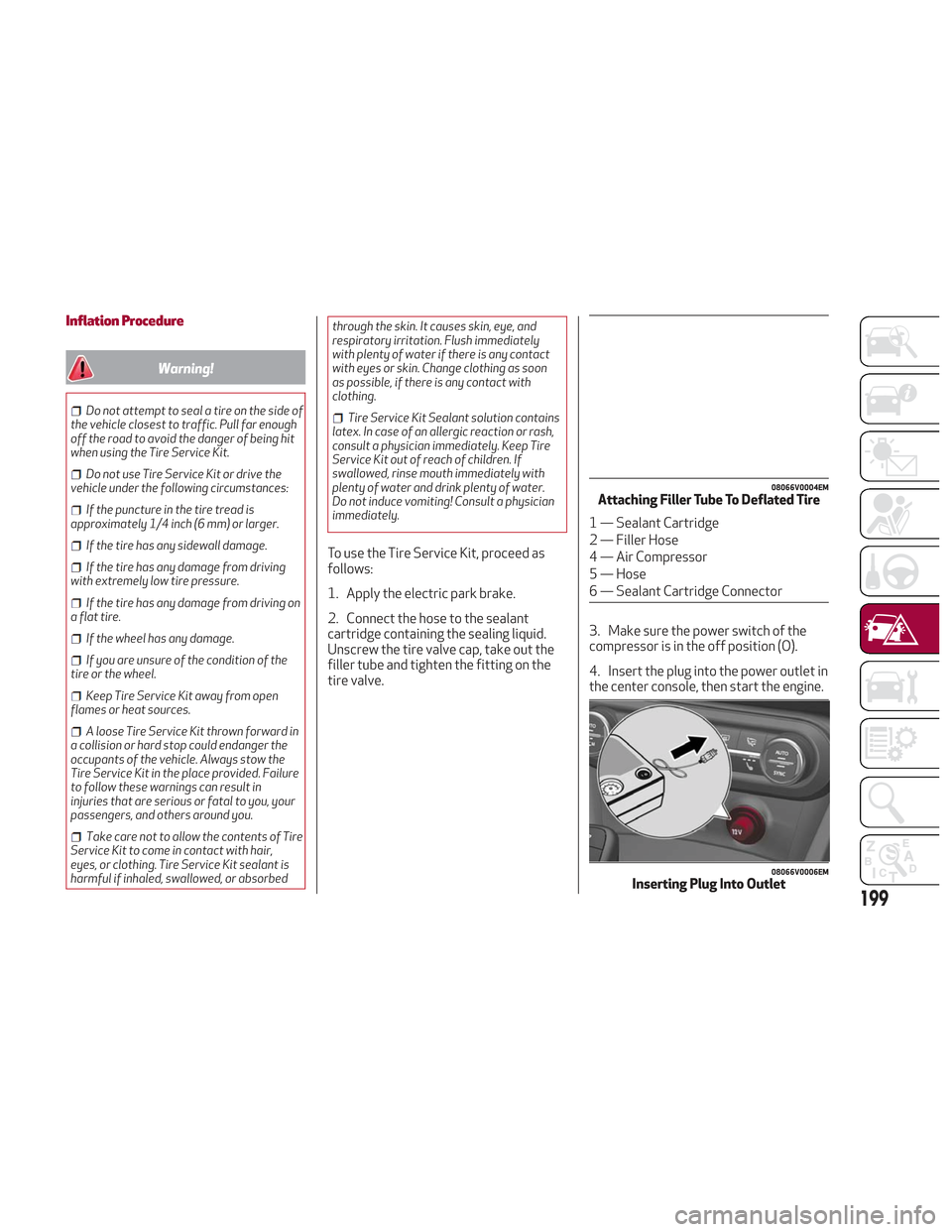
4. Insert the plug into the power outlet in
the center console, then start the engine.
08066V0004EMAttaching Filler Tube To Deflated Tire
1 — Sealant Cartridge
2 — Filler Hose
4 — Air Compressor
5 — Hose
6 — Sealant Cartridge Connector
08066V0006EMInserting Plug Into Outlet
199
Page 202 of 276
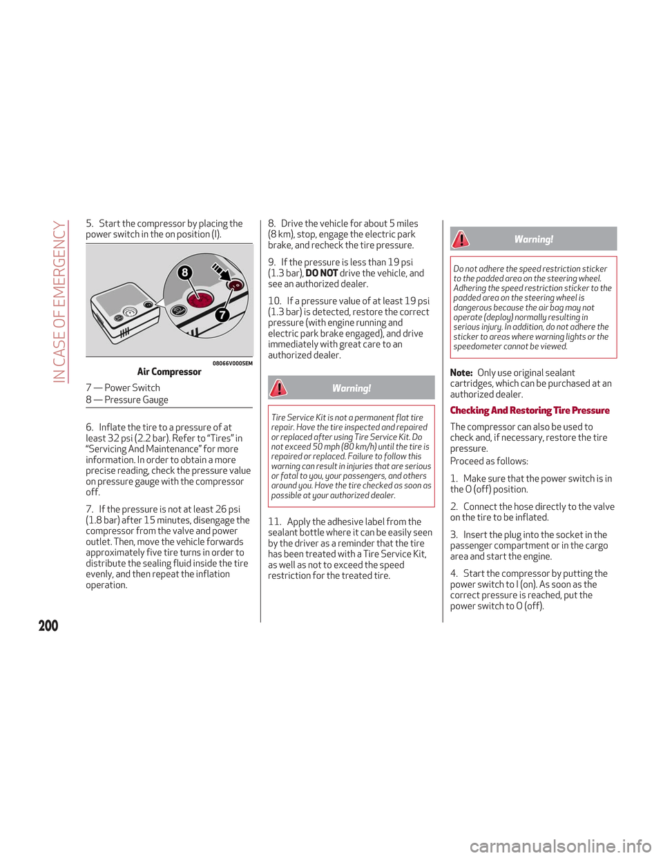
5. Start the compressor by placing the
power switch in the on position (I).
6. Inflate the tire to a pressure of at
least 32 psi (2.2 bar). Refer to “Tires” in
“Servicing And Maintenance” for more
information. In order to obtain a more
precise reading, check the pressure value
on pressure gauge with the compressor
off.
7. If the pressure is not at least 26 psi
(1.8 bar) after 15 minutes, disengage the
compressor from the valve and power
outlet. Then, move the vehicle forwards
approximately five tire turns in order to
distribute the sealing fluid inside the tire
evenly, and then repeat the inflation
operation.8. Drive the vehicle for about 5 miles
(8 km), stop, engage the electric park
brake, and recheck the tire pressure.
9. If the pressure is less than 19 psi
(1.3 bar),
DO NOTdrive the vehicle, and
see an authorized dealer.
10. If a pressure value of at least 19 psi
(1.3 bar) is detected, restore the correct
pressure (with engine running and
electric park brake engaged), and drive
immediately with great care to an
authorized dealer.
Warning!
Tire Service Kit is not a permanent flat tire
repair. Have the tire inspected and repaired
or replaced after using Tire Service Kit. Do
not exceed 50 mph (80 km/h) until the tire is
repaired or replaced. Failure to follow this
warning can result in injuries that are serious
or fatal to you, your passengers, and others
around you. Have the tire checked as soon as
possible at your authorized dealer.
11. Apply the adhesive label from the
sealant bottle where it can be easily seen
by the driver as a reminder that the tire
has been treated with a Tire Service Kit,
as well as not to exceed the speed
restriction for the treated tire.
Warning!
Do not adhere the speed restriction sticker
to the padded area on the steering wheel.
Adhering the speed restriction sticker to the
padded area on the steering wheel is
dangerous because the air bag may not
operate (deploy) normally resulting in
serious injury. In addition, do not adhere the
sticker to areas where warning lights or the
speedometer cannot be viewed.
Note: Only use original sealant
cartridges, which can be purchased at an
authorized dealer.
Checking And Restoring Tire Pressure
The compressor can also be used to
check and, if necessary, restore the tire
pressure.
Proceed as follows:
1. Make sure that the power switch is in
the O (off) position.
2. Connect the hose directly to the valve
on the tire to be inflated.
3. Insert the plug into the socket in the
passenger compartment or in the cargo
area and start the engine.
4. Start the compressor by putting the
power switch to I (on). As soon as the
correct pressure is reached, put the
power switch to O (off).
08066V0005EMAir Compressor
7 — Power Switch
8 — Pressure Gauge
200
IN CASE OF EMERGENCY
Page 205 of 276
Cable Disconnection
Once the engine is started, remove the
connection cables in reverse sequence,
as described below:
1. Disconnect the negative (-) end of the
jumper cable from the remote negative (-)
post of the vehicle with the discharged
battery.
2. Disconnect the negative end (-) of the
jumper cable from the negative (-) post of
the booster battery.
3. Disconnect the opposite end of the
positive (+) jumper cable from the
positive (+) post of the booster battery.
4. Disconnect the positive (+) end of the
jumper cable from the positive (+) post of
the vehicle with the discharged battery.
If frequent jump starting is required to
start your vehicle, you should have the
battery and charging system inspected at
an authorized dealer.
Caution!
Accessories plugged into the vehicle power
outlets draw power from the vehicle’s
battery, even when not in use (i.e., cellular
phones, etc.). Eventually, if plugged in long
enough without engine operation, the
vehicle’s battery will discharge sufficiently
to degrade battery life and/or prevent the
engine from starting.
Bump Starting
Never jump start the engine by pushing,
towing or coasting downhill. You cannot
start a vehicle with an automatic
transmission by pushing it.
Caution!
Accessories plugged into the vehicle power
outlets draw power from the vehicle’s
battery, even when not in use (i.e., cellular
phones, etc.). Eventually, if plugged in long
enough without engine operation, the
vehicle’s battery will discharge sufficiently
to degrade battery life and/or prevent the
engine from starting.
ENGINE OVERHEATING
Engine overheating may occur in
situations such as (but not limited to)
extreme environmental temperatures or
frequent engine stops/starts. If the
engine becomes overheated, the Engine
Temperature Warning Light in the
instrument cluster will illuminate along
with a dedicated message. Refer to
"Warning Lights And Messages On The
Instrument Panel" in the "Getting To
Know Your Instrument Panel" for more
information.
In any of the following situations, you can
reduce the potential for overheating by
taking the appropriate action.
On the highways — slow down.
In city traffic — while stopped, place
the transmission in NEUTRAL, but do not
increase engine idle speed.
Note: There are steps that you can take
to slow down an impending overheat
condition:
If your air conditioner (A/C) is on, turn
it off. The A/C system adds heat to the
engine cooling system and turning the
A/C off can help remove this heat.
You can also turn the temperature
control to maximum heat, the mode
control to floor and the blower control to
high. This allows the heater core to act
as a supplement to the radiator and aids
in removing heat from the engine cooling
system.
203
Page 221 of 276

The vehicle is equipped with an
Intelligent Battery Sensor (IBS), which is
able to measure the charge and discharge
voltage and calculate the charge level
and the general condition of the battery.
The sensor is placed next to the negative
terminal (-) of the battery.For a correct charge/discharge
procedure, the charge voltage must go
through the IBS sensor.
1. Turn the charger on and follow the
instructions on the user's manual to
completely recharge the battery.
2. When the battery is charged, turn the
charger off before disconnecting it from
the battery.
3. Disconnect the black cable terminal of
the battery charger and then the red
cable terminal.
4. Refit the protective cover of the
positive terminal of the battery and the
access cover to the battery
compartment.
Note:
If a "quick-type" battery charger is
used with the battery fitted on the
vehicle, before connecting it disconnect
both cables of the battery itself. Do not
use a "quick-type" battery charger to
provide the starting voltage.
DEALER SERVICE
The following pages contain instructions
on the required maintenance from the
technical personnel who designed the
vehicle.
In addition to these specific maintenance
instructions specified for routine
scheduled servicing, there are other
components which may require periodic
maintenance or replacement over the
vehicle’s life cycle.
Engine Oil
Engine Oil Level Check
To ensure correct engine lubrication, the
oil must always be kept at the prescribed
level (see "Engine Compartment" in this
chapter).
Check the oil level at regular intervals, for
example every 1,864 miles (3,000 km).
It must be checked about five minutes
after stopping the engine.
Full operating temperature must be
reached. The vehicle must also be parked
on as level a surface as possible.
The engine oil level can be checked using
the Information and Entertainment
system. To access the function, activate
the main menu (MENU button) and select
the following options in sequence:
1. “Applications”
2. “My Car”
3. “Oil level”
09036V0002EMBattery
1 — Protective Cover
2 — Negative Post (Nut)
219
Page 224 of 276
Replacing The Windshield Wiper Blades
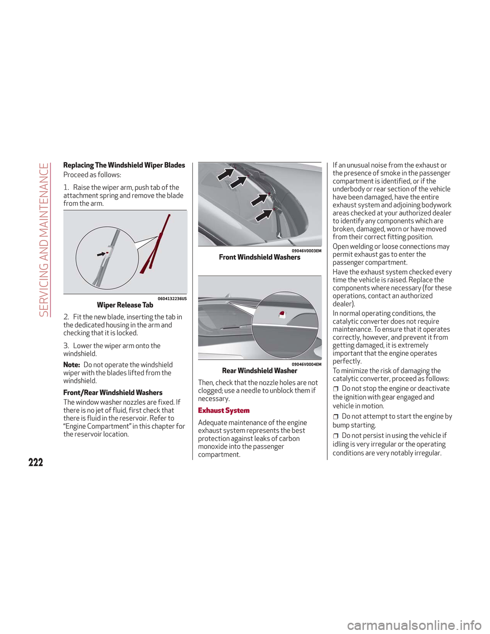
Proceed as follows:
1. Raise the wiper arm, push tab of the
attachment spring and remove the blade
from the arm.
2. Fit the new blade, inserting the tab in
the dedicated housing in the arm and
checking that it is locked.
3. Lower the wiper arm onto the
windshield.
Note:Do not operate the windshield
wiper with the blades lifted from the
windshield.
Front/Rear Windshield Washers
The window washer nozzles are fixed. If
there is no jet of fluid, first check that
there is fluid in the reservoir. Refer to
“Engine Compartment” in this chapter for
the reservoir location. Then, check that the nozzle holes are not
clogged; use a needle to unblock them if
necessary.
Exhaust System
Adequate maintenance of the engine
exhaust system represents the best
protection against leaks of carbon
monoxide into the passenger
compartment.If an unusual noise from the exhaust or
the presence of smoke in the passenger
compartment is identified, or if the
underbody or rear section of the vehicle
have been damaged, have the entire
exhaust system and adjoining bodywork
areas checked at your authorized dealer
to identify any components which are
broken, damaged, worn or have moved
from their correct fitting position.
Open welding or loose connections may
permit exhaust gas to enter the
passenger compartment.
Have the exhaust system checked every
time the vehicle is raised. Replace the
components where necessary (for these
operations, contact an authorized
dealer).
In normal operating conditions, the
catalytic converter does not require
maintenance. To ensure that it operates
correctly, however, and prevent it from
getting damaged, it is extremely
important that the engine operates
perfectly.
To minimize the risk of damaging the
catalytic converter, proceed as follows:
Do not stop the engine or deactivate
the ignition with gear engaged and
vehicle in motion.
Do not attempt to start the engine by
bump starting.
Do not persist in using the vehicle if
idling is very irregular or the operating
conditions are very notably irregular.
0604132236USWiper Release Tab
09046V0003EMFront Windshield Washers
09046V0004EMRear Windshield Washer
222
SERVICING AND MAINTENANCE
Page 273 of 276
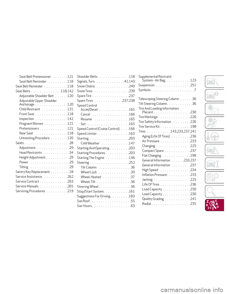
Seat Belt Pretensioner.......121
Seat Belt Reminder ..........118
Seat Belt Reminder ...........118
Seat Belts ............. .118,142
Adjustable Shoulder Belt ......120
Adjustable Upper Shoulder
Anchorage .............. .120
Child Restraint ............131
Front Seat .............. .118
Inspection .............. .142
Pregnant Women ...........121
Pretensioners .............121
Rear Seat .............. .118
Untwisting Procedure ........120
Seats .....................28
Adjustment ...............29
Head Restraints ............34
Height Adjustment ...........29
Power ..................29
Tilting ..................29
Sentry Key Replacement .........18
Service Assistance ............262
Service Contract .............263
Service Manuals .............265
Servicing Procedures ..........219Shoulder Belts
............. .118
Signals, Turn ............. .41,143
Snow Chains ............... .240
Snow Tires ................ .239
Spare Tire ................ .237
Spare Tires .............237,238
Speed Control Accel/Decel ............. .165
Cancel ................ .166
Resume ............... .165
Set .................. .165
Speed Control (Cruise Control) . . . .166
Speed Limiter .............. .163
Starting .................
.203
Cold
Weather .............147
Starting And Operating .........203
Starting Procedures ...........203
Starting The Engine ...........146
Steering ................. .252
Tilt Column ...............36
Wheel Lock ...............20
Wheel, Heated .............37
Wheel, Tilt ................36
Steering Wheel ...............36
Stop/Start System ............161
Suggestions For Driving .........183
Sun Roof ...................55
Sun Visors ..................63 Supplemental Restraint
System - Air Bag ............123
Suspension ............... .251
Symbols ....................7
Telescoping Steering Column ......36
Tilt Steering Column ............36
Tire And Loading Information Placard ................ .230
Tire Markings .............. .226
Tire Safety Information .........226
Tire Service Kit ..............198
Tires ...........143,233,237,241
Aging (Life Of Tires) .........236
Air Pressure ..............233
Changing ............... .225
Compact Spare ............237
Flat Changing .............198
General Information ......233,237
General Information .........237
High Speed ..............234
Inflation Pressure ...........233
Jacking ................ .225
Life Of Tires ..............236
Load Capacity .............230
Load Capacity .............230
Quality
Grading ............241
Radial ................. .235