2018 Alfa Romeo Stelvio Battery
[x] Cancel search: BatteryPage 165 of 276

Note:After setting the ignition to STOP
and having closed the driver side door,
wait at least one minute before
disconnecting the electrical supply from
the battery. When reconnecting the
electrical supply to the battery, make
sure that the ignition is in the STOP mode
and the driver side door is closed.
SPEED LIMITER
Description
This feature allows the speed of the
vehicle to be limited to speeds, which can
be set by the driver.
The maximum speed can be set with the
vehicle stationary or in motion. The
minimum speed that can be set is 18 mph
(30mk/h).
When this feature is active, the vehicle
speed depends on the pressing of the
accelerator pedal until the programmed
speed limit is reached (see "Speed Limit
Programming" paragraph).
Activation
The feature can be activated/
deactivated through the Information and
Entertainment System.
Activating The Device
To access this feature on the main menu,
select the following items in sequence:
"Settings", "Safety", “Speed Limiter” and
“ON”.
The activation of this feature is signaled
by the displaying of the green symbol
along with the last speed set. The Speed
Limiter feature can remain active
concurrently with the Speed Control
system. If a speed limit below the one
indicated in the Speed Control is
selected, the Speed Control speed will be
lowered to that of the Speed Limiter. This
function remains available in RACE mode.
Speed Limit Programming
The speed limit can be programmed
through the Information and
Entertainment System.
To access the function on the main menu,
select the following items in sequence:
"Settings", "Safety" and "Speed Limiter
Set Speed".
By turning the Rotary Pad, the speed
increases by 5 mph (5 km/h), from a
minimum of 18 mph (30 km/h) to a
maximum of 112 mph (180 km/h).
Exceeding The Programmed Speed
By fully pressing the accelerator pedal,
the programmed speed can be exceeded
even with the device active (e.g. in the
event of overtaking).
The device is disabled until the speed
drops below the set limit, after which it
reactivates automatically.
07126V0002EMBattery Power Supply
1 — Socket
2 — Sensor
3 — Connector
07136S0001EMSpeed Limiter Display
163
Page 190 of 276

HAZARD WARNING LIGHTS
The Hazard Warning flasher switch is
located in the switch bank below the
radio screen.Push the switch once to
turn the hazard warning
flasher on. When the
switch is activated, all
directional turn signals
will flash on and off to
warn oncoming traffic
of an emergency. Push the switch a
second time to turn the hazard warning
flashers off.
This is an emergency warning system and
it should not be used when the vehicle is
in motion. Use it when your vehicle is
disabled and is creating a safety hazard
for other motorists.
When you must leave the vehicle to seek
assistance, the hazard warning flashers
will continue to operate even though the
ignition is cycled to STOP.
Caution!
Prolonged use of the hazard warning
flashers may discharge the vehicle’s battery.
Panic Brake Assist (PBA) System
The PBA system is designed to improve
the vehicle’s braking capacity during
emergency braking.
For further details about the Panic Brake
Assist System, refer to the "Active
Safety Systems" section in the "Safety"
chapter.
BULB REPLACEMENT
General Instructions
Before replacing a bulb, check the
contacts for oxidation.
Replace blown bulbs with others of the
same type and power.
After replacing a headlight bulb,
always check its alignment.
When a light is not working, check that
the corresponding fuse is intact before
changing the bulb. For the location of
fuses, refer to “Fuses” in this chapter.
Note: In some particular climate
conditions, such as low temperature,
humidity, or after washing the vehicle, a
thin condensation layer may form on the
internal surfaces of the front and rear
headlights. This condensation will
disappear after switching on the
headlights.
0403132206USHazard Warning Switch
188
IN CASE OF EMERGENCY
Page 195 of 276
3. Install bulb, making sure that it is
correctly inserted fully.
4. Close the protective cover on the lens.
5. Install liftgate lamp in the correct
position, inserting it first on one side, and
then pressing on the other side until it
clicks into place.
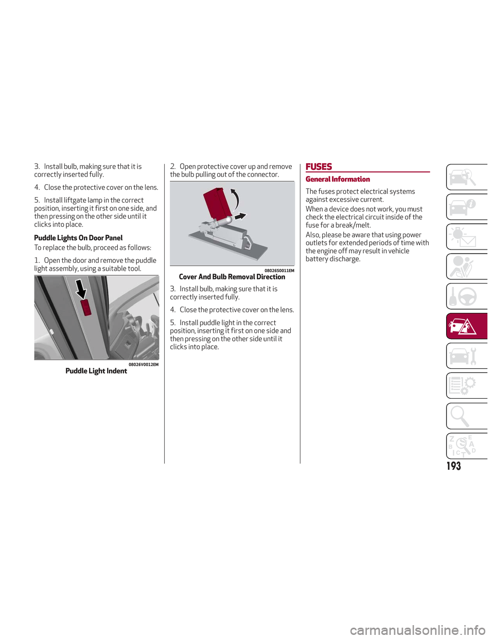
Puddle Lights On Door Panel
To replace the bulb, proceed as follows:
1. Open the door and remove the puddle
light assembly, using a suitable tool.2. Open protective cover up and remove
the bulb pulling out of the connector.
3. Install bulb, making sure that it is
correctly inserted fully.
4. Close the protective cover on the lens.
5. Install puddle light in the correct
position, inserting it first on one side and
then pressing on the other side until it
clicks into place.FUSES
General Information
The fuses protect electrical systems
against excessive current.
When a device does not work, you must
check the electrical circuit inside of the
fuse for a break/melt.
Also, please be aware that using power
outlets for extended periods of time with
the engine off may result in vehicle
battery discharge.
08026V0012EMPuddle Light Indent
08026S0011EMCover And Bulb Removal Direction
193
Page 203 of 276
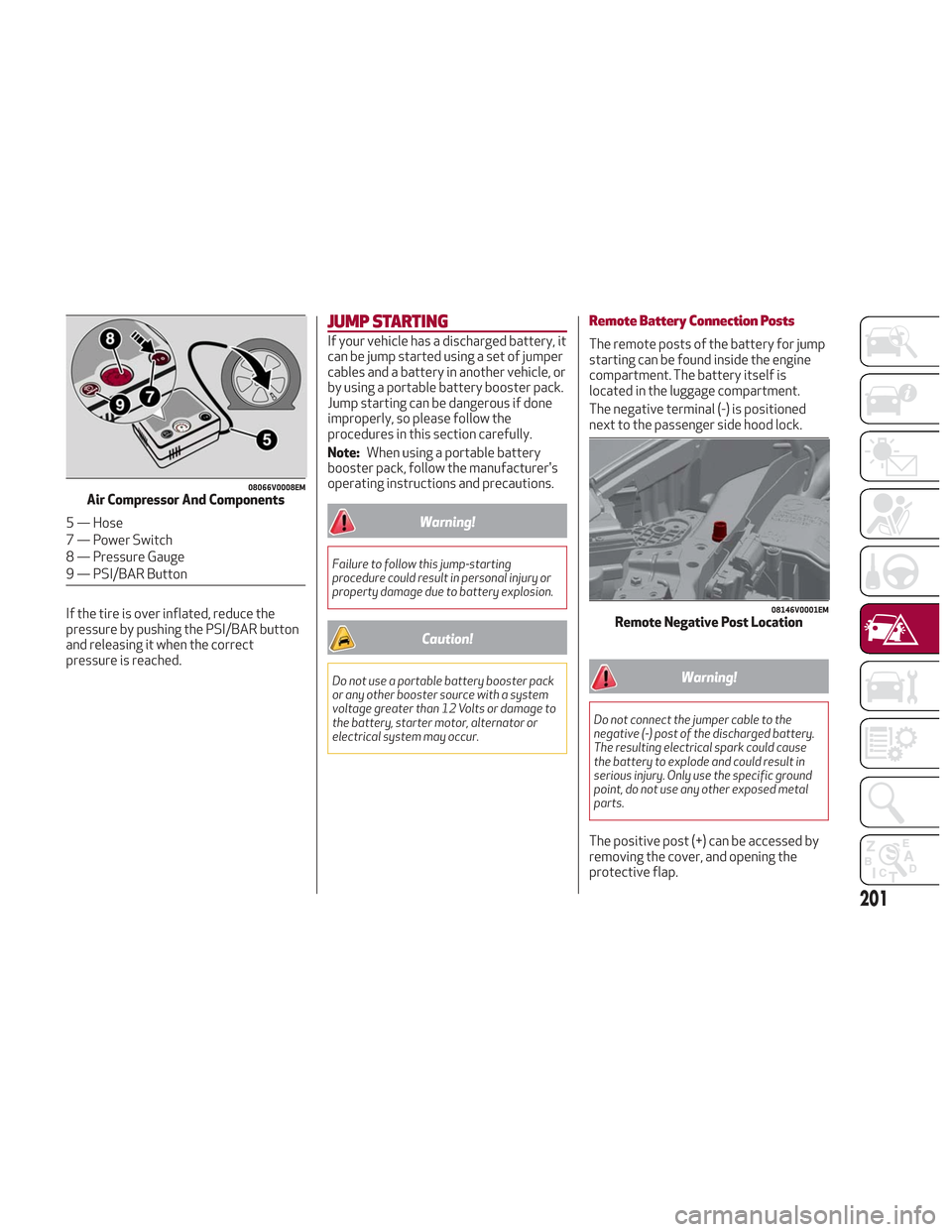
If the tire is over inflated, reduce the
pressure by pushing the PSI/BAR button
and releasing it when the correct
pressure is reached.
JUMP STARTING
If your vehicle has a discharged battery, it
can be jump started using a set of jumper
cables and a battery in another vehicle, or
by using a portable battery booster pack.
Jump starting can be dangerous if done
improperly, so please follow the
procedures in this section carefully.
Note:When using a portable battery
booster pack, follow the manufacturer's
operating instructions and precautions.
Warning!
Failure to follow this jump-starting
procedure could result in personal injury or
property damage due to battery explosion.
Caution!
Do not use a portable battery booster pack
or any other booster source with a system
voltage greater than 12 Volts or damage to
the battery, starter motor, alternator or
electrical system may occur.
Remote Battery Connection Posts
The remote posts of the battery for jump
starting can be found inside the engine
compartment. The battery itself is
located in the luggage compartment.
The negative terminal (-) is positioned
next to the passenger side hood lock.
Warning!
Do not connect the jumper cable to the
negative (-) post of the discharged battery.
The resulting electrical spark could cause
the battery to explode and could result in
serious injury. Only use the specific ground
point, do not use any other exposed metal
parts.
The positive post (+) can be accessed by
removing the cover, and opening the
protective flap.
08066V0008EMAir Compressor And Components
5 — Hose
7 — Power Switch
8 — Pressure Gauge
9 — PSI/BAR Button
08146V0001EMRemote Negative Post Location
201
Page 204 of 276
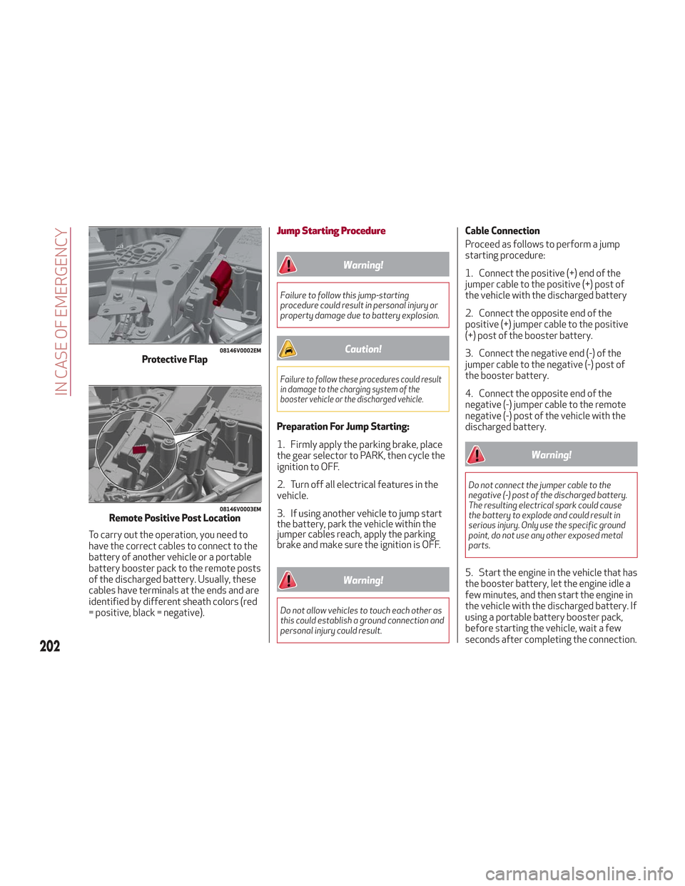
To carry out the operation, you need to
have the correct cables to connect to the
battery of another vehicle or a portable
battery booster pack to the remote posts
of the discharged battery. Usually, these
cables have terminals at the ends and are
identified by different sheath colors (red
= positive, black = negative).
Jump Starting Procedure
Warning!
Failure to follow this jump-starting
procedure could result in personal injury or
property damage due to battery explosion.
Caution!
Failure to follow these procedures could result
in damage to the charging system of the
booster vehicle or the discharged vehicle.
Preparation For Jump Starting:
1. Firmly apply the parking brake, place
the gear selector to PARK, then cycle the
ignition to OFF.
2. Turn off all electrical features in the
vehicle.
3. If using another vehicle to jump start
the battery, park the vehicle within the
jumper cables reach, apply the parking
brake and make sure the ignition is OFF.
Warning!
Do not allow vehicles to touch each other as
this could establish a ground connection and
personal injury could result.
Cable Connection
Proceed as follows to perform a jump
starting procedure:
1. Connect the positive (+) end of the
jumper cable to the positive (+) post of
the vehicle with the discharged battery
2. Connect the opposite end of the
positive (+) jumper cable to the positive
(+) post of the booster battery.
3. Connect the negative end (-) of the
jumper cable to the negative (-) post of
the booster battery.
4. Connect the opposite end of the
negative (-) jumper cable to the remote
negative (-) post of the vehicle with the
discharged battery.
Warning!
Do not connect the jumper cable to the
negative (-) post of the discharged battery.
The resulting electrical spark could cause
the battery to explode and could result in
serious injury. Only use the specific ground
point, do not use any other exposed metal
parts.
5. Start the engine in the vehicle that has
the booster battery, let the engine idle a
few minutes, and then start the engine in
the vehicle with the discharged battery. If
using a portable battery booster pack,
before starting the vehicle, wait a few
seconds after completing the connection.
08146V0002EMProtective Flap
08146V0003EMRemote Positive Post Location
202
IN CASE OF EMERGENCY
Page 205 of 276
Cable Disconnection
Once the engine is started, remove the
connection cables in reverse sequence,
as described below:
1. Disconnect the negative (-) end of the
jumper cable from the remote negative (-)
post of the vehicle with the discharged
battery.
2. Disconnect the negative end (-) of the
jumper cable from the negative (-) post of
the booster battery.
3. Disconnect the opposite end of the
positive (+) jumper cable from the
positive (+) post of the booster battery.
4. Disconnect the positive (+) end of the
jumper cable from the positive (+) post of
the vehicle with the discharged battery.
If frequent jump starting is required to
start your vehicle, you should have the
battery and charging system inspected at
an authorized dealer.
Caution!
Accessories plugged into the vehicle power
outlets draw power from the vehicle’s
battery, even when not in use (i.e., cellular
phones, etc.). Eventually, if plugged in long
enough without engine operation, the
vehicle’s battery will discharge sufficiently
to degrade battery life and/or prevent the
engine from starting.
Bump Starting
Never jump start the engine by pushing,
towing or coasting downhill. You cannot
start a vehicle with an automatic
transmission by pushing it.
Caution!
Accessories plugged into the vehicle power
outlets draw power from the vehicle’s
battery, even when not in use (i.e., cellular
phones, etc.). Eventually, if plugged in long
enough without engine operation, the
vehicle’s battery will discharge sufficiently
to degrade battery life and/or prevent the
engine from starting.
ENGINE OVERHEATING
Engine overheating may occur in
situations such as (but not limited to)
extreme environmental temperatures or
frequent engine stops/starts. If the
engine becomes overheated, the Engine
Temperature Warning Light in the
instrument cluster will illuminate along
with a dedicated message. Refer to
"Warning Lights And Messages On The
Instrument Panel" in the "Getting To
Know Your Instrument Panel" for more
information.
In any of the following situations, you can
reduce the potential for overheating by
taking the appropriate action.
On the highways — slow down.
In city traffic — while stopped, place
the transmission in NEUTRAL, but do not
increase engine idle speed.
Note: There are steps that you can take
to slow down an impending overheat
condition:
If your air conditioner (A/C) is on, turn
it off. The A/C system adds heat to the
engine cooling system and turning the
A/C off can help remove this heat.
You can also turn the temperature
control to maximum heat, the mode
control to floor and the blower control to
high. This allows the heater core to act
as a supplement to the radiator and aids
in removing heat from the engine cooling
system.
203
Page 211 of 276

SERVICING AND MAINTENANCE
Correct servicing permits the
performance of the vehicle to be
maintained over time, as well as limited
running costs and safeguarding the
efficiency of the safety systems.
This chapter explains how.SCHEDULED SERVICING.......210
ENGINE COMPARTMENT .......215
BATTERY RECHARGING ........218
DEALER SERVICE ............219
RAISING THE VEHICLE .........225
TIRES .................. .226
DEPARTMENT OF TRANSPORTATION
UNIFORM TIRE QUALITY GRADES .241
STORING THE VEHICLE ........242
BODYWORK...............242
INTERIORS ............... .244
209
Page 213 of 276
Heavy Usage Of The Vehicle
If the vehicle is used under one of the following conditions:
Dusty roads.
Short, repeated journeys less than 4 miles (7-8 km) at sub-zero outside temperatures.
Engine often idling or driving long distances at low speeds or long periods of inactivity.
In the event of a long period of inactivity.
The following checks must be carried out more often than indicated in the Scheduled Servicing Plan:
Check cleanliness of hood and liftgate locks, cleanliness and lubrication of linkage.
Visually inspect conditions of: engine, transmission, pipes and hoses (exhaust/fuel system/brakes) and rubber elements
(sleeves/bushes, etc.).
Check battery charge and battery fluid level (electrolyte).
Visually inspect conditions of the accessory drive belts.
Check and, if necessary, change engine oil and replace oil filter.
Check and, if necessary, replace cabin air filter.
Check and, if necessary, replace air cleaner.
Severe Duty All Models
Change Engine Oil at 4,000 miles (6,500 km) if the vehicle is operated in a dusty and off-road environment or is operated
predominately at idle or only very low engine RPM’s. This type of vehicle use is considered Severe Duty.
211