2018 Alfa Romeo Stelvio Turn
[x] Cancel search: TurnPage 178 of 276

LANE DEPARTURE WARNING
(LDW) SYSTEM — IF EQUIPPED
Description
The Lane Departure Warning system uses
a forward looking camera located on the
windshield to detect lane markings and
measure vehicle position within the lane
boundaries.
When one or both lane limits are
detected and the vehicle passes over one
without an activated turn signal, the
system emits a visual as well as an
acoustic signal.
If the vehicle continues to go beyond the
line of the lane without any intervention
from the driver, the surpassed line will
light up on the display (left or right) to
urge the driver to bring the vehicle back
into the limits of the lane.
Caution!
Do not tamper with nor operate on the
camera. Do not close the openings in the
aesthetic cover located under the interior
rear view mirror. In the event of a failure of
the camera, contact your authorized dealer.
The camera may have limited or absent
operation due to weather conditions such
as: heavy rain, hail, thick fog, heavy snow,
formation of ice layers on the windshield.
Camera operation may also be
compromised by the presence of dust,
condensation, dirt or ice on the windshield,
by traffic conditions (e.g. vehicles that are
driving not aligned with yours, vehicle
driving in a transverse or opposite way on
the same lane, bend with a small radius of
curvature), by road surface conditions and
by driving conditions (e.g. off-road driving).
Make sure the windshield is always clean.
Use specific detergents and clean cloths to
avoid scratching the windshield. The camera
operation may also be limited or absent in
some driving, traffic and road surface
conditions.
If the windshield must be replaced due to
scratches, chipping or breakage, contact
exclusively your authorized dealer. Do not
replace the windshield on your own. It is
advisable to replace the windshield if it is
damaged in the area of the camera.
System Activation/Deactivation
The system is activated/deactivated by
pushing the button located on the end of
the multifunction lever.
Note: When the engine is started, the
system maintains the operating mode
that was selected when it was turned
OFF.
Activation Conditions
Once turned on, the system becomes
active only if the following conditions are
met:
The vehicle speed is above 37 mph
(60 km/h).
The lane limit lines are visible at least
on one side.
07226S0001EMLane Departure Warning System Activation/Deactivation Button
176
STARTING AND OPERATING
Page 179 of 276

There are suitable visibility conditions.
The road is straight or with wide radius
bends.
A suitable distance is kept from the
vehicle in front.
The turn signal is not active.
Symbols And Messages On The Display
The Lane Departure Warning system
advises the driver when the vehicle
leaves the driving lane by showing
symbols and messages on the instrument
cluster display.
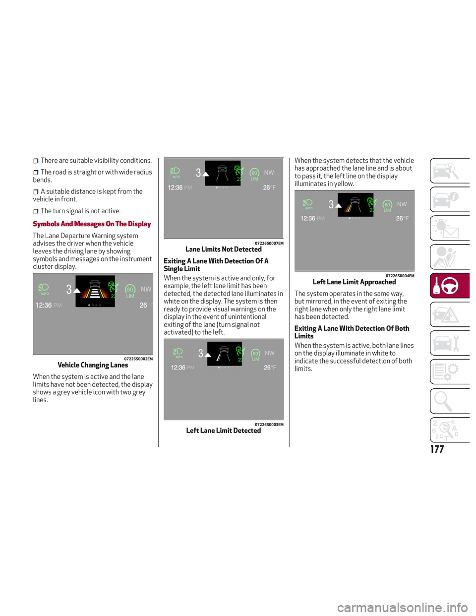
When the system is active and the lane
limits have not been detected, the display
shows a grey vehicle icon with two grey
lines. Exiting A Lane With Detection Of A
Single Limit
When the system is active and only, for
example, the left lane limit has been
detected, the detected lane illuminates in
white on the display. The system is then
ready to provide visual warnings on the
display in the event of unintentional
exiting of the lane (turn signal not
activated) to the left.When the system detects that the vehicle
has approached the lane line and is about
to pass it, the left line on the display
illuminates in yellow.
The system operates in the same way,
but mirrored, in the event of exiting the
right lane when only the right lane limit
has been detected.
Exiting A Lane With Detection Of Both
Limits
When the system is active, both lane lines
on the display illuminate in white to
indicate the successful detection of both
limits.
07226S0002EMVehicle Changing Lanes
07226S0007EMLane Limits Not Detected
07226S0003EMLeft Lane Limit Detected
07226S0004EMLeft Lane Limit Approached
177
Page 180 of 276

When lane limits are detected, the
system is ready to provide indications in
case the driver unintentionally leaves the
lane (turn signal not activated).
As the Lane Departure Warning system
detects the lane limits while the vehicle is
in motion, it will adjust the display
accordingly (from white to yellow and
yellow to white, and increase their
thickness).If a line is crossed, the driver is alerted by
an audible signal as well as the visual
indication in the instrument cluster. The
signal is emitted through the speakers on
the side of the lane limit which is being
crossed (eg. if the vehicle is exceeding
the left line of the lane, the audible signal
will come from the speakers on the left of
the vehicle).
Changing The System Settings
The system's sensitivity can be set
through the Information and
Entertainment System. Sensitivity “High”
or “Low” can be selected.
To access the function, from the main
menu select the following in order:
1. “Settings.”
2. “Safety.”
3. “Lane Departure Warning.”
4. “Sensitivity.”Limited Operation Warning
If a message appears on the display, a
condition limiting the Lane Departure
Warning system operation may have
occurred. This could be an obstruction of
the camera view, or a fault in the system.
If an obstruction is detected, clean the
area of the windshield by the interior rear
view mirror.
Although the vehicle can still be driven in
normal conditions, the system may not
function properly.
When the conditions limiting the system
are corrected, it will go back to normal
operation. Should a fault persist, contact
an authorized dealer.
System Failure Warning
If the system turns off and
appears on
the display, it means that there is a
system fault.
In this case, it is still possible to drive the
vehicle, but you are advised to contact an
authorized dealer as soon as possible.
07226S0005EMBoth Lane Limits Detected07226S0006EMRight Lane Limit Approached
178
STARTING AND OPERATING
Page 182 of 276

The table below shows the approximate
distances for each area:
AreaDistance From The
Rear Of The Vehicle
Red 0–11.8
inches
(0–30 cm)
Yellow 11.8 inches to 3.3 feet
(30cm–1m)
Green 3.3feetormore(1m
or more)
Messages On The Display
If the liftgate is opened, the camera will
not detect any obstacle behind the
vehicle. The display will show a dedicated
warning message.
Make sure the liftgate is closed by
pushing next to the lock until it clicks.
Important Notes
Ice, snow or mud on the surface of the
camera may reduce its sensitivity. It is
important to keep the camera surface
clean, and free from debris.
When parking, be aware of obstacles
that may be above or below the camera
range.
REFUELING THE VEHICLE
Refueling The Vehicle
Before refueling, make sure that the fuel
type is correct.
Also, stop the engine before refueling.
Note: An inefficient catalytic converter
leads to harmful exhaust emissions, thus
contributing to air pollution.
Caution!
Never introduce leaded fuel to the tank,
even in small amounts in an emergency, as
this would damage the catalytic converter
beyond repair.
Refueling Capacity
To ensure that you fill the tank
completely, top off twice after the first
click of the fuel nozzle.
Further top-off could cause faults in the
fuel feeding system.
Refueling Procedure
The fuel filler door is unlocked when the
central door locking system is unlocked.
It is automatically locked when the
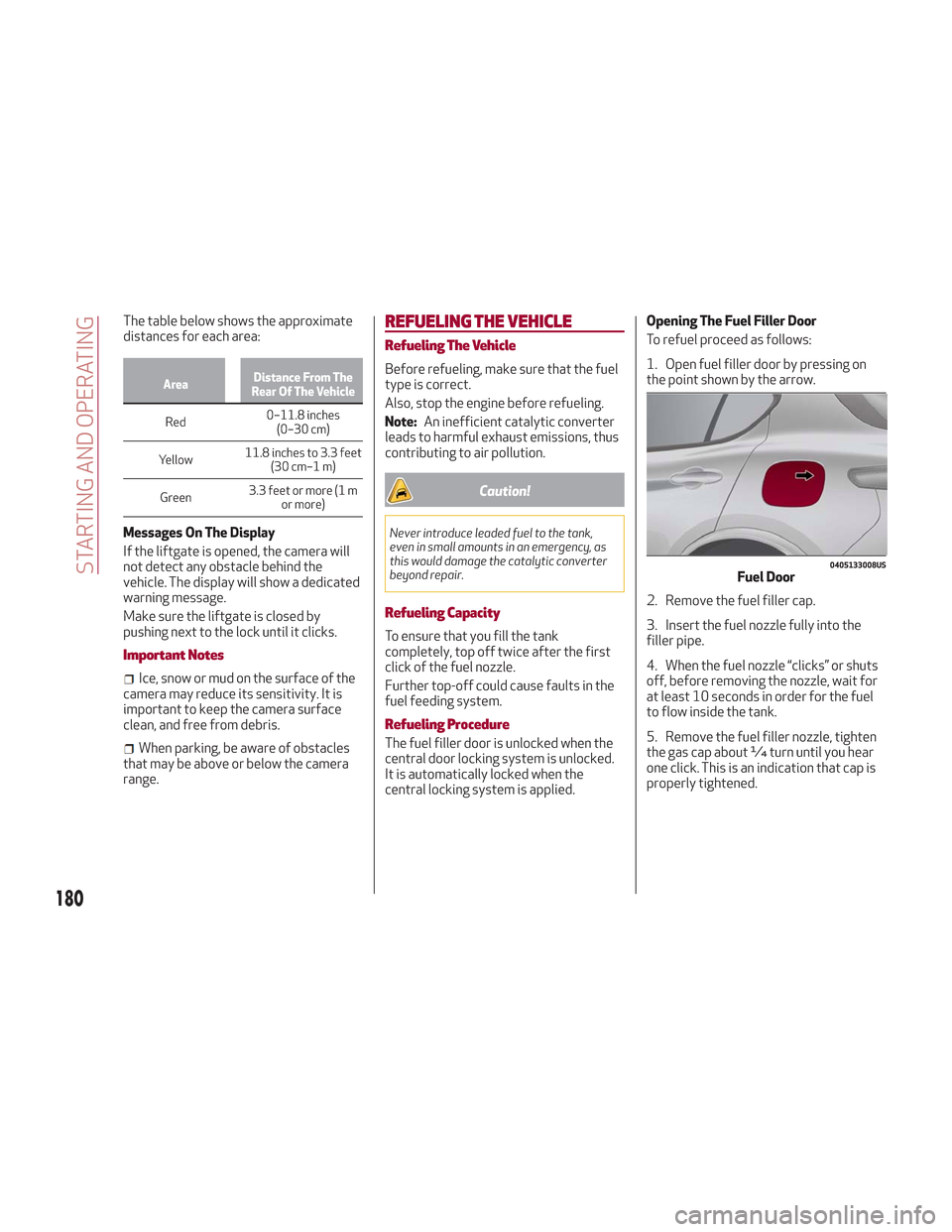
central locking system is applied. Opening The Fuel Filler Door
To refuel proceed as follows:
1. Open fuel filler door by pressing on
the point shown by the arrow.
2. Remove the fuel filler cap.
3. Insert the fuel nozzle fully into the
filler pipe.
4. When the fuel nozzle “clicks” or shuts
off, before removing the nozzle, wait for
at least 10 seconds in order for the fuel
to flow inside the tank.
5. Remove the fuel filler nozzle, tighten
the gas cap about ¼ turn until you hear
one click. This is an indication that cap is
properly tightened.
0405133008USFuel Door
180
STARTING AND OPERATING
Page 184 of 276

Warning!
Never have any smoking materials lit in or
near the vehicle when the fuel door is open
or the tank is being filled.
Never add fuel when the engine is running.
This is in violation of most state and federal
fire regulations and may cause the MIL to
turn on.
A fire may result if gasoline is pumped
into a portable container that is inside of a
vehicle. You could be burned. Always place
gas containers on the ground while filling.
Note: If the filler compartment is
washed with a pressure washer, keep it at
a distance of at least 8 inches (20 cm).
VEHICLE LOADING
Certification Label
As required by National Highway Traffic
Safety Administration regulations, your
vehicle has a certification label affixed to
the driver's side door or pillar.
This label contains the month and year of
manufacture, Gross Vehicle Weight
Rating (GVWR), Gross Axle Weight Rating
(GAWR) front and rear, and Vehicle
Identification Number (VIN). A
Month-Day-Hour (MDH) number is
included on this label and indicates the
Month, Day and Hour of manufacture. The
bar code that appears on the bottom of
the label is your VIN.
Gross Vehicle Weight Rating
(GVWR)
The GVWR is the total permissible
weight of your vehicle including driver,
passengers, vehicle, options and cargo.
The label also specifies maximum
capacities of front and rear axle systems
(GAWR). Total load must be limited so
GVWR and front and rear GAWR are not
exceeded.
Payload
The payload of a vehicle is defined as the
allowable load weight a truck can carry,
including the weight of the driver, all
passengers, options and cargo.
Gross Axle Weight Rating (GAWR)
The GAWR is the maximum permissible
load on the front and rear axles. The load
must be distributed in the cargo area so
that the GAWR of each axle is not
exceeded.
Each axle GAWR is determined by the
components in the system with the
lowest load carrying capacity (axle,
springs, tires or wheels). Heavier axles or
suspension components sometimes
specified by purchasers for increased
durability does not necessarily increase
the vehicle's GVWR.
Tire Size
The tire size on the Vehicle Certification
Label represents the actual tire size on
your vehicle. Replacement tires must be
equal to the load capacity of this tire size.
Rim Size
This is the rim size that is appropriate for
the tire size listed.
Inflation Pressure
This is the cold tire inflation pressure for
your vehicle for all loading conditions up
to full GAWR.
182
STARTING AND OPERATING
Page 186 of 276

Electric Devices
Use electrical systems only for the
amount of time needed. The rear window
defroster, additional headlights,
windshield wipers and heater blower fan
require a considerable amount of energy;
increasing the current uptake increases
fuel consumption (by up to +25% when
city driving).
Climate Control System
Using the climate control system will
increase consumption: use standard
ventilation when the temperature
outside permits.
Devices For Aerodynamic Control
The use of non-certified devices for
aerodynamic control may adversely
affect air drag and consumption levels.
Driving Style
Starting
Do not warm up the engine at low or high
revs when the vehicle is stationary; this
causes the engine to warm up more
slowly, thereby increasing fuel
consumption and emissions. It is
therefore advisable to drive off
immediately, slowly, avoiding high
speeds: by doing this the engine will
warm up more quickly.Unnecessary Actions
Avoid revving up when starting at traffic
lights or before stopping the engine. This
action is unnecessary and causes
increased fuel consumption and
pollution.
Gear Selection
Use a high gear when traffic and road
conditions allow it. Using a low gear for
faster acceleration will increase fuel
consumption. Improper use of a high gear
increases consumption, emissions and
engine wear.
Max. Speed
Fuel consumption considerably increases
as speed increases. Maintain a constant
speed, avoiding unnecessary braking and
acceleration, which cost in terms of both
fuel consumption and emissions.
Acceleration
Accelerating violently severely affects
consumption and emissions: acceleration
should be gradual and should not exceed
the maximum torque.
Conditions Of Use
Cold Starting
Short trips and frequent cold starts will
not allow the engine to reach optimum
operating temperature. This results in a
significant increase in consumption
levels (from +15 to +30% in city driving)
and emissions.Traffic And Road Conditions
High fuel consumption is caused by heavy
traffic, for instance when travelling in
traffic with frequent use of low gears or
in cities with many traffic lights. Winding
mountain roads and rough road surfaces
also adversely affect consumption.
Stops In Traffic
During prolonged stops (e.g. railway
crossings), turn off the engine.
Performance
This vehicle is equipped with an engine
capable of delivering exceptionally fast
acceleration and speed:
Peak power: 505 HP at 6500 rpm.
Peak torque: 443 ft-lbs at
2500–5000 rpm.
Top speed: 177 mph (285 km/h).
Acceleration from 0 to 60 mph (0 to
100 km/h): 3.9 seconds.
For safe driving, it is essential,
particularly during the first days of use,
to get to know the car by driving carefully
and gradually discovering its
performance.
184
STARTING AND OPERATING
Page 190 of 276

HAZARD WARNING LIGHTS
The Hazard Warning flasher switch is
located in the switch bank below the
radio screen.Push the switch once to
turn the hazard warning
flasher on. When the
switch is activated, all
directional turn signals
will flash on and off to
warn oncoming traffic
of an emergency. Push the switch a
second time to turn the hazard warning
flashers off.
This is an emergency warning system and
it should not be used when the vehicle is
in motion. Use it when your vehicle is
disabled and is creating a safety hazard
for other motorists.
When you must leave the vehicle to seek
assistance, the hazard warning flashers
will continue to operate even though the
ignition is cycled to STOP.
Caution!
Prolonged use of the hazard warning
flashers may discharge the vehicle’s battery.
Panic Brake Assist (PBA) System
The PBA system is designed to improve
the vehicle’s braking capacity during
emergency braking.
For further details about the Panic Brake
Assist System, refer to the "Active
Safety Systems" section in the "Safety"
chapter.
BULB REPLACEMENT
General Instructions
Before replacing a bulb, check the
contacts for oxidation.
Replace blown bulbs with others of the
same type and power.
After replacing a headlight bulb,
always check its alignment.
When a light is not working, check that
the corresponding fuse is intact before
changing the bulb. For the location of
fuses, refer to “Fuses” in this chapter.
Note: In some particular climate
conditions, such as low temperature,
humidity, or after washing the vehicle, a
thin condensation layer may form on the
internal surfaces of the front and rear
headlights. This condensation will
disappear after switching on the
headlights.
0403132206USHazard Warning Switch
188
IN CASE OF EMERGENCY
Page 191 of 276

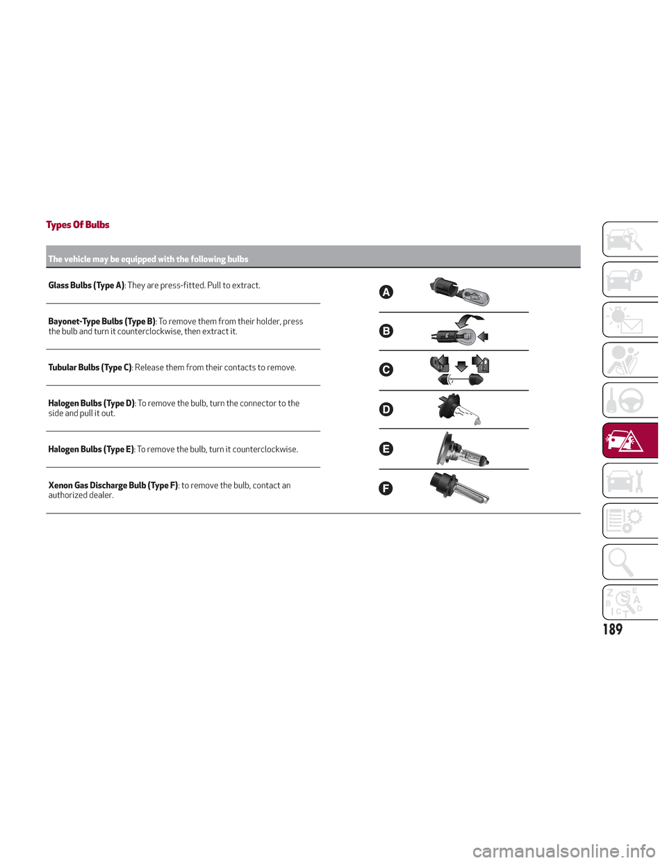
Types Of Bulbs
The vehicle may be equipped with the following bulbs
Glass Bulbs (Type A):
They are press-fitted. Pull to extract.
Bayonet-Type Bulbs (Type B) : To remove them from their holder, press
the bulb and turn it counterclockwise, then extract it.
Tubular Bulbs (Type C) : Release them from their contacts to remove.
Halogen Bulbs (Type D) : To remove the bulb, turn the connector to the
side and pull it out.
Halogen Bulbs (Type E) : To remove the bulb, turn it counterclockwise.
Xenon Gas Discharge Bulb (Type F) : to remove the bulb, contact an
authorized dealer.
189