Page 57 of 122

Instrument and control functions
3-43
3
EAU15306
Si destan d
The sidestand is located on the left
side of the frame. Raise the sidestand
or lower it with your foot while holding
the vehicle upright.
TIP
The built-in sidestand switch is part of
the ignition circuit cut-off system,
which cuts the ignition in certain situa-
tions. (See the following section for an
explanation of the ignition circuit cut-
off system.)
WARNING
EWA10242
The vehicle must not be ri dden with
the si destan d d own, or if the si de-
stan d cannot b e properly move d up
(or does not stay up), otherwise the
si destan d coul d contact the g round
an d d istract the operator, resultin g
in a possib le loss of control.
Yamaha’s ig nition circuit cut-off
system has been desi gne d to assist
the operator in fulfillin g the respon-
si bility of raising the sidestan d b e-
fore startin g off. Therefore, check
this system re gularly an d have a
Yamaha dealer repair it if it does not
function properly.
EAU63430
I g nition circuit cut-off system
The ignition circuit cut-off system
(comprising the sidestand switch,
clutch switch and neutral switch) has
the following functions.
It prevents starting when the
transmission is in gear and the
sidestand is up, but the clutch le-
ver is not pulled.
It prevents starting when the
transmission is in gear and the
clutch lever is pulled, but the side-
stand is still down.
It cuts the running engine when
the transmission is in gear and the
sidestand is moved down.
Periodically check the operation of the
ignition circuit cut-off system accord-
ing to the following procedure.
UBP9E0E0.book Page 43 Wednesday, February 8, 2017 8:34 AM
Page 58 of 122

Instrument and control functions
3-44
3
With the engine turned off:
1. Move the sidestand down.
2.
Make sure that the start/engine stop
switch is set to “ ”.
3. Turn the key on.
4. Shift the transmission into the neutral position.
5.
Push the “ ” side of the start/engine
stop switch.
Does the engine start?
With the engine still running:
6. Move the sidestand up.
7. Keep the clutch lever pulled.
8. Shift the transmission into gear.
9. Move the sidestand down.
Does the engine stall?
After the engine has stalled:
10. Move the sidestand up.
11. Keep the clutch lever pulled.
12.
Push the “ ” side of the
start/engine stop switch.
Does the engine start?
The system is OK. The motorcycle can
be ridden.
The neutral switch may not be working
correctly.
The motorcycle should not be ridden
until checked by a Yamaha dealer.
The sidestand switch may not be
working correctly.
The motorcycle should not be ridden
until checked by a Yamaha dealer.
The clutch switch may not be working
correctly.
The motorcycle should not be ridden
until checked by a Yamaha dealer.
WARNING
The vehicle must be placed on the centerstand during this inspection.
If a malfunction is noted, have a Yamaha dealer check the system
before riding.
YES NO
YESNO
YESNO
UBP9E0E0.book Page 44 Wednesday, February 8, 2017 8:34 AM
Page 59 of 122

Instrument and control functions
3-45
3
EAU49453
Auxiliary DC jack
WARNING
EWA14361
To prevent electrical shock or short-
circuiting , make sure that the cap is
installe d when the auxiliary DC jack
is not bein g use d.
NOTICE
ECA15432
The accessory connecte d to the
auxiliary DC jack shoul d not b e used
with the en gine turne d off, an d the
loa d must never exceed 30 W (2.5 A),
otherwise the fuse may blow or the
b attery may d ischarge.
This vehicle is equipped with an auxil-
iary DC jack.
A 12-V accessory connected to the
auxiliary DC jack can be used when the
key is in the “ON” position and should
only be used when the engine is run-
ning.
To use the auxiliary DC jack
1. Turn the key to “OFF”.
2. Remove the auxiliary DC jack cap.
3. Turn the accessory off.
4. Insert the accessory plug into the auxiliary DC jack. 5. Turn the key to “ON”, and then
start the engine. (See page 5-2.)
6. Turn the accessory on.
1. Auxiliary DC jack cap
1
1. Auxiliary DC jack
1
UBP9E0E0.book Page 45 Wednesday, February 8, 2017 8:34 AM
Page 60 of 122

For your safety – pre-operation checks
4-1
4
EAU63440
Inspect your vehicle each time you use it to make sure the vehicle is in safe oper-
ating condition. Always follow the inspection and maintenance procedures and
schedules described in the Owner’s Manual.
WARNING
EWA11152
Failure to inspect or maintain the vehicle properly increases the possibility
of an acci dent or equipment d amage. Do not operate the vehicle if you fin d
any pro blem. If a pro blem cannot be correcte d b y the proce dures provi ded
in this manual, have the vehicle inspecte d b y a Yamaha dealer.
Before using this vehicle, check the following points:
ITEM CHECKSPAGE
Fuel • Check fuel level in fuel tank.
• Refuel if necessary.
• Check fuel line for leakage.
• Check fuel tank breather hose and overflow hose for
obstructions, cracks or damage, and check hose con-
nections. 3-30,
3-32
En gine oil • Check oil level in engine.
• If necessary, add recommended oil to specified level.
• Check vehicle for oil leakage. 6-10
Final gear oil • Check vehicle for oil leakage. 6-14
Coolant • Check coolant level in reservoir.
• If necessary, add recommended coolant to specified
level.
• Check cooling system for leakage. 6-16
Front brake • Check operation.
• If soft or spongy, have Yamaha dealer bleed hydraulic
system.
• Check brake pads for wear.
• Replace if necessary.
• Check fluid level in reservoir.
• If necessary, add specified brake fluid to specified level.
• Check hydraulic system for leakage. 6-24,
6-25
Rear brake • Check operation.
• If soft or spongy, have Yamaha dealer bleed hydraulic
system.
• Check brake pads for wear.
• Replace if necessary.
• Check fluid level in reservoir.
• If necessary, add specified brake fluid to specified level.
• Check hydraulic system for leakage. 6-24,
6-25
Clutch • Check operation.
• If soft or spongy, have Yamaha dealer bleed hydraulic
system.
• Check hydraulic system for leakage. 6-22
UBP9E0E0.book Page 1 Wedne
sday, February 8, 2017 8:34 AM
Page 61 of 122

For your safety – pre-operation checks
4-2
4
Throttle grip • Make sure that operation is smooth.
• Check throttle grip free play.
• If necessary, have Yamaha dealer adjust throttle grip
free play and lubricate cable and grip housing. 6-18,
6-26
Wheels an d tires •Check for damage.
• Check tire condition and tread depth.
• Check air pressure.
• Correct if necessary. 6-19,
6-22
Brake an d shift pe dals • Make sure that operation is smooth.
• Lubricate pedal pivoting points if necessary.
6-27
Brake an d clutch le-
vers • Make sure that operation is smooth.
• Lubricate lever pivoting points if necessary.
6-27
Centerstan d, si de-
stan d • Make sure that operation is smooth.
• Lubricate pivots if necessary.
6-28
Chassis fasteners • Make sure that all nuts, bolts and screws are properly
tightened.
• Tighten if necessary. —
Instruments, li ghts,
si gnals an d switches • Check operation.
• Correct if necessary.
—
Si destan d switch • Check operation of ignition circuit cut-off system.
• If system is not working correctly, have Yamaha dealer
check vehicle. 3-43
ITEM CHECKS PAGE
UBP9E0E0.book Page 2 Wedne
sday, February 8, 2017 8:34 AM
Page 62 of 122
Operation and important rid ing points
5-1
5
EAU15952
Read the Owner’s Manual carefully to
become familiar with all controls. If
there is a control or function you do not
understand, ask your Yamaha dealer.
WARNING
EWA10272
Failure to familiarize yourself with
the controls can lead to loss of con-
trol, which coul d cause an acci dent
or injury.
EAU73450
TIP
This model is equipped with: a lean angle sensor to stop the en-
gine in case of turnover. In this
case, turn the key “OFF” and then
to “ON” before attempting to re-
start the engine. Failing to do so
will prevent the engine from start-
ing even though the engine will
crank when the start switch is
pushed.
an engine auto-stop system. The
engine stops automatically if left
idling for 20 minutes. In this case,
simply push the start switch to re-
start the engine.
UBP9E0E0.book Page 1 Wedne sday, February 8, 2017 8:34 AM
Page 63 of 122

Operation and important ri din g points
5-2
5
EAU58241
Startin g the eng ine
In order for the ignition circuit cut-off
system to enable starting, one of the
following conditions must be met:
The transmission is in the neutral
position.
The transmission is in gear with
the clutch lever pulled and the
sidestand up.
See page 3-43 for more informa-
tion.
1. Turn the key to “ON” and make sure that the start/engine stop
switch is set to “ ”.
The following warning lights and
indicator lights should come on for
a few seconds, then go off. Oil level warning light
Engine trouble warning light
Traction control system indi-
cator light
Cruise control indicator lights
Electronically adjustable sus-
pension system warning light
Immobilizer system indicator
light
NOTICE
ECA11834
If a warnin g or in dicator li ght does
not come on initially when the key is
turne d to “ON”, or if a warnin g or in-
d icator li ght remains on, see pa ge
3-4 for the correspon din g warnin g
an d in dicator li ght circuit check.
The ABS warning light should
come on when the key is turned to
“ON”, and then go off after travel-
ing at a speed of 10 km/h (6 mi/h)
or higher.
NOTICE
ECA17682
If the ABS warnin g li ght does not
come on an d then go off as ex-
plained above, see pa ge 3-4 for the
warnin g li ght circuit check.
2. Shift the transmission into the
neutral position. The neutral indi-
cator light should come on. If not,
ask a Yamaha dealer to check the
electrical circuit.
3. Start the engine by pushing the “ ” side of the start/engine
stop switch.
If the engine fails to start, release
the start/engine stop switch, wait
a few seconds, and then try again.
Each starting attempt should be
as short as possible to preserve
the battery. Do not crank the en-
gine more than 10 seconds on any
one attempt.
NOTICE
ECA11043
For maximum en gine life, never ac-
celerate har d when the en gine is
col d!
UBP9E0E0.book Page 2 Wedne sday, February 8, 2017 8:34 AM
Page 64 of 122

Operation and important rid ing points
5-3
5
EAU16673
Shiftin g
Shifting gears lets you control the
amount of engine power available for
starting off, accelerating, climbing hills,
etc.
The gear positions are shown in the il-
lustration.
TIP
To shift the transmission into the neu-
tral position, press the shift pedal down
repeatedly until it reaches the end of its
travel, and then slightly raise it.
NOTICE
ECA10261
Even with the transmission in
the neutral position, d o not
coast for lon g period s of time
with the en gine off, an d d o not
tow the motorcycle for lon g d is-
tances. The transmission is
properly lu bricated only when
the en gine is runnin g. Ina de-
quate lu brication may damag e
the transmission.
Always use the clutch while
chan gin g g ears to avoi d d am-
a g in g the en gine, transmission, an
d d rive train, which are not
d esi gne d to withstan d the
shock of force d shifting .
1. Shift pedal
2. Neutral position
1
2
6
5
4
3
2
1
N
UBP9E0E0.book Page 3 Wedne sday, February 8, 2017 8:34 AM
 1
1 2
2 3
3 4
4 5
5 6
6 7
7 8
8 9
9 10
10 11
11 12
12 13
13 14
14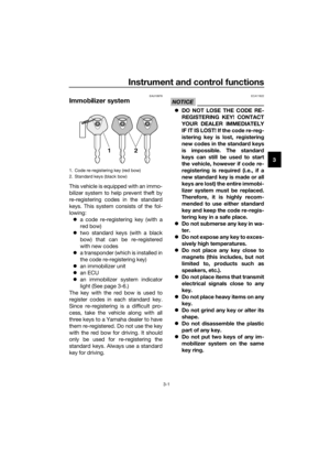 15
15 16
16 17
17 18
18 19
19 20
20 21
21 22
22 23
23 24
24 25
25 26
26 27
27 28
28 29
29 30
30 31
31 32
32 33
33 34
34 35
35 36
36 37
37 38
38 39
39 40
40 41
41 42
42 43
43 44
44 45
45 46
46 47
47 48
48 49
49 50
50 51
51 52
52 53
53 54
54 55
55 56
56 57
57 58
58 59
59 60
60 61
61 62
62 63
63 64
64 65
65 66
66 67
67 68
68 69
69 70
70 71
71 72
72 73
73 74
74 75
75 76
76 77
77 78
78 79
79 80
80 81
81 82
82 83
83 84
84 85
85 86
86 87
87 88
88 89
89 90
90 91
91 92
92 93
93 94
94 95
95 96
96 97
97 98
98 99
99 100
100 101
101 102
102 103
103 104
104 105
105 106
106 107
107 108
108 109
109 110
110 111
111 112
112 113
113 114
114 115
115 116
116 117
117 118
118 119
119 120
120 121
121