Page 49 of 122
Instrument and control functions
3-35
3
3. Install the rider seat height posi- tion adjuster so that the match
mark is aligned with the “H” mark
as shown.
4. Insert the projection on the rear of the rider seat into seat holder B as
shown.
TIP
Make sure that the rider seat is proper-
ly secured before riding.
1. Rider seat height position adjuster
1. Rider seat height position adjuster
2. “H” mark
3. Match mark
1. Projection
2. Seat holder B (for high position)
1
2 3
1
1
2
UBP9E0E0.book Page 35 Wednesday, February 8, 2017 8:34 AM
Page 50 of 122

Instrument and control functions
3-36
3
EAU58982
Win dshield
To suit the rider’s preference, the wind-
shield can be changed to one of four
positions.
To a djust the wind shield height
1. Loosen the windshield height po- sition adjusting knob on each side
of the windshield until resistance
is felt. NOTICE: Do not continue
turning the kno b after resis-
tance is felt. Otherwise, the
kno b coul d b e damag ed .
[ECA20211]
2. Pull the slide plate holders out-
ward, and then adjust the height of
the windshield.
3. Align the slide plate holders with the match marks at the desired
position.
TIP
Make sure that the slide plate
holders are aligned with the match
marks at the same height on both
sides of the windshield.
Make sure that the projection on
each slide plate holder fits into the
corresponding hole in the slide
plate.
4. Tighten the adjusting knobs.
1. Windshield height position adjusting knob
1. Slide plate holder
1
1
1. Match mark
2. Slide plate
2
1
UBP9E0E0.book Page 36 Wednesday, February 8, 2017 8:34 AM
Page 51 of 122

Instrument and control functions
3-37
3
EAU55424
A djustin g the front an d rear
suspension
This model is equipped with an elec-
tronically adjustable suspension sys-
tem. The preload of the rear shock
absorber and the damping forces of
both the front fork and rear shock ab-
sorber can be adjusted.
WARNING
EWA12423
Be sure to stop the vehicle before
makin g any settin g chan ges to the
multi-function meter unit. Chang ing
settin gs while ri din g can d istract the
operator an d increase the risk of an
acci dent.
Preloa d
When riding with luggage or a passen-
ger, use the preload adjusting function
to adjust the suspension system to
match the load. There are 4 preload
settings.
TIP
The preload adjusting function will
appear only when the engine is
running.
Changing the preload setting will
also adjust the front and rear sus-
pension damping forces accord-
ingly. See “Damping force” on
page 3-39 for more information.
About cold temperature opera-
tion:
• When using the preload adjust- ing function, there should be no
weight on the vehicle.
• When using the preload adjust- ing function at ambient temper-
atures near or below 0 °C (32
°F), to protect the preload ad- justing function motor, the elec-
tronically adjustable suspension
system warning light may come
on.
• The suspension will still operate as normal, only the preload ad-
justing function cannot be used.
• To reset the electronically ad- justable suspension system
warning light, wait approximate-
ly 6 minutes and then turn the
key to “OFF” or immediately
turn the key to “OFF” and then
wait 6 minutes.
• If the electronically adjustable suspension system warning
light remains on, have a
Yamaha dealer check the sus- pension system.
To adjust the preload
1. Turn the key to “ON”, start the en- gine, and then shift the transmis-
sion into neutral.
2. Push the menu switch “MENU” to switch the function display to the
preload adjusting function.
1. Function display
2. Preload adjusting function
3. Preload setting pictogram
GEAR
N
1
3
2
UBP9E0E0.book Page 37 Wednesday, February 8, 2017 8:34 AM
Page 52 of 122

Instrument and control functions
3-38
3
3. Use the select switch to select thedesired preload setting pictogram.
Select the suitable setting from
the following 4 pictograms ac-
cording to your load condition.
While the preload is being adjust-
ed, the information display will
show a group of dots moving in a
circle. Once the selected picto-
gram returns, the preload adjust-
ment is complete. While the preload is being adjusted,
the information display may change as
follows.
If the key is turned to “OFF” or the
engine is stopped while the pre-
load is being set, the following
preload setting pictogram will
flash to alert you that the current
preload setting does not match
the pictogram. If this occurs, ad-
just the preload again.
If the vehicle starts moving, the
following preload setting picto-
gram will flash to alert you that the
current preload setting does not
match the pictogram. If this oc-
curs, stop the vehicle and adjust
the preload again.1. Menu switch “MENU”
2. Select switch “ / ”
1. Solo riding
2. Solo riding and luggage
3. Passenger riding
4. Passenger riding and luggage
1
2
12
34
GEAR
N
GEAR
N
GEAR
N
GEAR
N
UBP9E0E0.book Page 38 Wednesday, February 8, 2017 8:34 AM
Page 53 of 122

Instrument and control functions
3-39
3
If the preload is adjusted repeat-
edly, the preload setting picto-
gram will flash 4 times and the
preload cannot be adjusted. Wait
approximately 6 minutes for the
preload adjusting function motor
to cool down, and then try adjust-
ing the preload again.
Dampin g force
Within each preload setting there are 3
damping force settings: “HARD”
(hard), “STD” (standard) and “SOFT”
(soft). When the preload setting is
changed, the damping force settings
will change accordingly. (The electron-
ically adjustable suspension system
will automatically adjust to the damp-
ing force settings last set for that pre-
load setting.) To further finely adjust
the damping force, each damping for-
ce setting can be set to 7 different lev-
els.
TIP
If the preload setting was not complet-
ed correctly: The damping force setting and
setting level will flash 4 times and
cannot be adjusted if you try to
adjust them while the vehicle is
stopped.
The preload setting pictogram will
flash and the damping force can-
not be adjusted if you try to adjust
it while the vehicle is moving.
Be sure that the preload has been set
correctly before adjusting the damping
force.
To adjust the damping force and
damping force setting level
1. Turn the key to “ON”.
2. Push the menu switch “MENU” to switch the function display to the
damping force adjusting function.
GEAR
1
HARD+3
GEAR
N
GEAR
N
GEAR
N
1. Damping force setting
2. Damping force setting level
GEAR
N
HARD+3
2
1
UBP9E0E0.book Page 39 Wednesday, February 8, 2017 8:34 AM
Page 54 of 122

Instrument and control functions
3-40
3
3. Use the select switch to select“HARD”, “STD” or “SOFT”.
4. Push the menu switch “MENU”.
5. Use the select switch to select the desired level for the damping for-
ce setting.
TIP
The damping force setting can be set to
7 levels (+3, +2, +1, 0, –1, –2 and –3).
“+3” is the hardest level and “–3” is the
softest level.
6. Push the menu switch “MENU”.
If the vehicle moves while you are ad-
justing the damping force, the informa-
tion display will change to the display
mode.
WARNING
EWA16421
The rear shock ab sorber assem bly
contains hi ghly pressurize d nitro gen
g as. Read and un derstan d the fol-
lowin g information before han dlin g
the shock a bsor ber assem bly.
Do not tamper with or attempt
to open the cylind er assembly.
Do not su bject the shock a b-
sor ber assem bly to an open
flame or other hi gh heat source.
This may cause the unit to ex-
plo de due to excessive g as
pressure.
1. Function display
2. Damping force adjusting function
1. Damping force setting
1. Damping force setting level
GEAR
N
STD 0
1
2
GEAR
N
HARD 01
GEAR
N
HARD
+31
1. Damping force adjusting function
2. Damping force setting
3. Preload setting pictogram
GEAR
N
HARD+3
GEAR
1
HARD+3
1
2
3
UBP9E0E0.book Page 40 Wednesday, February 8, 2017 8:34 AM
Page 55 of 122
Instrument and control functions
3-41
3
Do not deform or damag e the
cylin der in any way. Cylin der
d amag e will result in poor
d ampin g performance.
Do not d ispose of a damag ed or
worn-out shock a bsor ber as-
sem bly yourself. Take the shock
a b sor ber assem bly to a Yamaha
d ealer for any service.
EAU49704
Carriers
This motorcycle is equipped with a
standard carrier, and with an additional
carrier located under the passenger
seat. This additional carrier extends the
loading surface and the loading capac-
ity of the standard carrier.
To use the additional carrier, consult a
Yamaha dealer.
Stan dar d carrier
A dditional carrier
WARNING
EWA15483
Do not exceed the maximum
loa d of 204 k g (450 l b) for the ve-
hicle.
Do not sit on an d never ri de with
a passen ger on the stan dar d or
a dd itional carrier.
1. Standard carrier
1. Additional carrier
1
1
UBP9E0E0.book Page 41 Wednesday, February 8, 2017 8:34 AM
Page 56 of 122
Instrument and control functions
3-42
3
Do not exceed the standar d car-
rier capacity of 5.0 k g (11 lb ).
Do not exceed the additional
carrier capacity of 5.0 k g (11 l b).
NOTICE
ECA16822
Do not lift the vehicle by either carri-
er.
EAU49491
Lugg ag e strap hol ders
There are four luggage strap holders
below the passenger seat.
1. Luggage strap holder
1
UBP9E0E0.book Page 42 Wednesday, February 8, 2017 8:34 AM
 1
1 2
2 3
3 4
4 5
5 6
6 7
7 8
8 9
9 10
10 11
11 12
12 13
13 14
14 15
15 16
16 17
17 18
18 19
19 20
20 21
21 22
22 23
23 24
24 25
25 26
26 27
27 28
28 29
29 30
30 31
31 32
32 33
33 34
34 35
35 36
36 37
37 38
38 39
39 40
40 41
41 42
42 43
43 44
44 45
45 46
46 47
47 48
48 49
49 50
50 51
51 52
52 53
53 54
54 55
55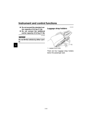 56
56 57
57 58
58 59
59 60
60 61
61 62
62 63
63 64
64 65
65 66
66 67
67 68
68 69
69 70
70 71
71 72
72 73
73 74
74 75
75 76
76 77
77 78
78 79
79 80
80 81
81 82
82 83
83 84
84 85
85 86
86 87
87 88
88 89
89 90
90 91
91 92
92 93
93 94
94 95
95 96
96 97
97 98
98 99
99 100
100 101
101 102
102 103
103 104
104 105
105 106
106 107
107 108
108 109
109 110
110 111
111 112
112 113
113 114
114 115
115 116
116 117
117 118
118 119
119 120
120 121
121

.
Do not exceed the additional
carrier capacity of 5.0 k g (11 l b).
NOTICE
ECA16822")