Page 49 of 116
Instrument and control functions
4-23
4
3. Remove the bolts, and then install
the bolts in the desired position.
4. Install the windshield to the high position by installing the bolts, and
then tighten the bolts to the spec-
ified torque. WARNING! A loose
win dshiel d coul d cause an acci-
d ent. Be sure to ti ghten the
screws to the specified torque.
[EWA15511]
5. Place the bolt access covers, and
then install the quick fasteners.
To chan ge the win dshield height to
the low position 1. Remove the bolt access covers by removing the quick fasteners.
2. Remove the windshield by remov- ing the bolts.
3. Remove the bolts, and then install the bolts in the desired position.
1. Bolt
1. Bolt
1. Bolt
1
1
1
1
1
1
1. Bolt
Tightenin g torque:
Windshield bolt: 8 N·m (0.8 kgf·m, 5.8 lb·ft)
1. Bolt access cover
1
1
1
UB74E0E0.book Page 23 Tuesday, May 2, 2017 1:04 PM
Page 50 of 116
Instrument and control functions
4-24
4
4. Install the windshield to the lowposition by installing the bolts, and
then tighten the bolts to the spec-
ified torque. WARNING! A loose
win dshield could cause an acci-
d ent. Be sure to ti ghten the
screws to the specified torque.
[EWA15511]
5. Place the bolt access covers, and
then install the quick fasteners.
1. Bolt
1. Bolt
1. Bolt
1
1
1
1
1
1
Tightening torque:
Windshield bolt: 8 N·m (0.8 kgf·m, 5.8 lb·ft)
UB74E0E0.book Page 24 Tuesday, May 2, 2017 1:04 PM
Page 51 of 116

Instrument and control functions
4-25
4
EAU46833
Han dle bar position
The handlebar can be adjusted to one
of two positions to suit the rider’s pref-
erence. Have a Yamaha dealer adjust
the position of the handlebar.
EAU14893
A djustin g the shock a bsor ber
assem blies
WARNING
EWA10211
Always a djust both shock ab sorber
assem blies equally, otherwise poor
han dlin g an d loss of sta bility may re-
sult.
Each shock absorber assembly is
equipped with a spring preload adjust-
ing ring.
NOTICE
ECA10102
To avoi d d amag ing the mechanism,
d o not attempt to turn b eyond the
maximum or minimum settin gs.
Adjust the spring preload as follows.
To increase the spring preload and
thereby harden the suspension, turn
the adjusting ring on each shock ab-
sorber assembly in direction (a). To de-
crease the spring preload and thereby
soften the suspension, turn the adjust-
ing ring on each shock absorber as-
sembly in direction (b).
�z Align the appropriate notch in the
adjusting ring with the position in-
dicator on the shock absorber.
�z Use the spring preload adjusting
tool included in the owner’s tool
kit to make this adjustment.
1. Handlebar
1
UB74E0E0.book Page 25 Tuesday, May 2, 2017 1:04 PM
Page 52 of 116

Instrument and control functions
4-26
4
EAU15306
Si destan d
The sidestand is located on the left
side of the frame. Raise the sidestand
or lower it with your foot while holding
the vehicle upright.
TIP
The built-in sidestand switch is part of
the ignition circuit cut-off system,
which cuts the ignition in certain situa-
tions. (See the following section for an
explanation of the ignition circuit cut-
off system.)
WARNING
EWA10242
The vehicle must not be ri dden with
the si destan d d own, or if the si de-
stan d cannot b e properly move d up
(or does not stay up), otherwise the
si destan d coul d contact the g round
an d d istract the operator, resultin g
in a possi ble loss of control.
Yamaha’s ig nition circuit cut-off
system has been desi gne d to assist
the operator in fulfillin g the respon-
si bility of raising the sidestan d b e-
fore startin g off. Therefore, check
this system re gularly an d have a
Yamaha dealer repair it if it does not
function properly.
1. Spring preload adjusting ring
2. Special wrench
3. Position indicator
Sprin g preloa d setting :
Minimum (soft):
1
Standard: 3
Maximum (hard): 5
1 2345
2
1
(a)(b)
3
UB74E0E0.book Page 26 Tuesday, May 2, 2017 1:04 PM
Page 53 of 116
Instrument and control functions
4-27
4
EAU78690
Ig nition circuit cut-off system
The ignition circuit cut-off system
works with the sidestand switch and
brake light switches. It has the follow-
ing functions.
�z It prevents the engine from start-
ing when the sidestand is down.
�z It prevents the engine from start-
ing if the brakes are not applied.
�z It will stop the running engine if the
sidestand is moved down.
Periodically check the operation of the
ignition circuit cut-off system accord-
ing to the following procedure.
UB74E0E0.book Page 27 Tuesday, May 2, 2017 1:04 PM
Page 54 of 116

Instrument and control functions
4-28
4
With the engine turned off:
1. Move the sidestand down.
2. Turn the main switch on.
3. Keep the front or rear brake applied.
Push the start switch.
4.
Does the engine start?
With the engine still off:
5. Move the sidestand up.
6. Keep the front or rear brake applied.
Push the start switch.
7.
Does the engine start?
With the engine still running:
8. Move the sidestand down.
Does the engine stall?
The system is OK. The vehicle can be
ridden.
The sidestand switch may not be
working correctly.
The vehicle should not be ridden
until
checked by a Yamaha dealer.
The brake switch may not be working
correctly.
The vehicle should not be ridden until
checked by a Yamaha dealer.
The sidestand switch may not be
working correctly.
The vehicle should not be ridden until
checked by a Yamaha dealer.
WARNING
The vehicle must be placed on the centerstand during this inspection.
If a malfunction is noted, have a Yamaha dealer check the system
before riding.
NO YES
YES NO
YESNO
UB74E0E0.book Page 28 Tuesday, May 2, 2017 1:04 PM
Page 55 of 116

Instrument and control functions
4-29
4
EAU78213
Auxiliary DC jack
WARNING
EWA14361
To prevent electrical shock or short-
circuiting , make sure that the cap is
installe d when the auxiliary DC jack
is not bein g use d.
NOTICE
ECA15432
The accessory connecte d to the
auxiliary DC jack shoul d not b e used
with the en gine turne d off, an d the
loa d must never excee d 12 W (1 A),
otherwise the fuse may blow or the
b attery may d ischarge.
This vehicle is equipped with an auxil-
iary DC jack located within storage
compartment A.
A 12-V accessory connected to the
auxiliary DC jack can be used when the
main switch is in the “ON” position and
should only be used when the engine is
running.
To use the auxiliary DC jack
1. Open storage compartment A. (See page 3-9.)
2. Turn the main switch off.
3. Remove the auxiliary DC jack cap.
4. Turn the accessory off. 5. Insert the accessory plug into the
auxiliary DC jack.
6. Turn the main switch on, and then start the engine. (See page 6-2.)
7. Turn the accessory on.
1. Auxiliary DC jack cap
1
1. Auxiliary DC jack
1
UB74E0E0.book Page 29 Tuesday, May 2, 2017 1:04 PM
Page 56 of 116

For your safety – pre-operation checks
5-1
5
EAU63440
Inspect your vehicle each time you use it to make sure the vehicle is in safe oper-
ating condition. Always follow the inspection and maintenance procedures and
schedules described in the Owner’s Manual.
WARNING
EWA11152
Failure to inspect or maintain the vehicle properly increases the possibility
of an acci dent or equipment d amage. Do not operate the vehicle if you fin d
any pro blem. If a pro blem cannot be correcte d b y the proce dures provi ded
in this manual, have the vehicle inspecte d b y a Yamaha dealer.
Before using this vehicle, check the following points:
ITEM CHECKSPAGE
Fuel • Check fuel level in fuel tank.
• Refuel if necessary.
• Check fuel line for leakage.
• Check fuel tank overflow hose for obstructions, cracks
or damage, and check hose connection. 4-18,
4-19
En gine oil • Check oil level in engine.
• If necessary, add recommended oil to specified level.
• Check vehicle for oil leakage. 7-9
Final transmission oil • Check vehicle for oil leakage. 7-12
Coolant • Check coolant level in reservoir.
• If necessary, add recommended coolant to specified
level.
• Check cooling system for leakage. 7-13
Front brake • Check operation.
• If soft or spongy, have Yamaha dealer bleed hydraulic
system.
• Check brake pads for wear.
• Replace if necessary.
• Check fluid level in reservoir.
• If necessary, add specified brake fluid to specified level.
• Check hydraulic system for leakage. 7-22,
7-23, 7-23
Rear brake • Check operation.
• If soft or spongy, have Yamaha dealer bleed hydraulic
system.
• Check brake pads for wear.
• Replace if necessary.
• Check fluid level in reservoir.
• If necessary, add specified brake fluid to specified level.
• Check hydraulic system for leakage. 7-22,
7-23, 7-23
Throttle grip • Make sure that operation is smooth.
• Check throttle grip free play.
• If necessary, have Yamaha dealer adjust throttle grip
free play and lubricate cable and grip housing. 7-18,
7-26
UB74E0E0.book Page 1 Tuesday, May 2, 2017 1:04 PM
 1
1 2
2 3
3 4
4 5
5 6
6 7
7 8
8 9
9 10
10 11
11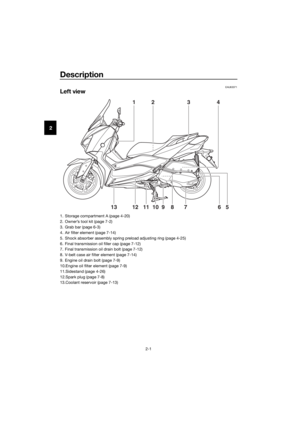 12
12 13
13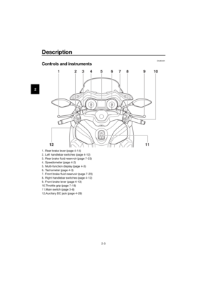 14
14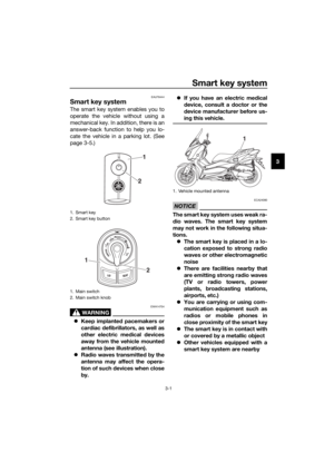 15
15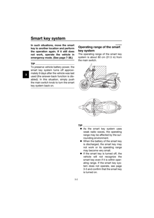 16
16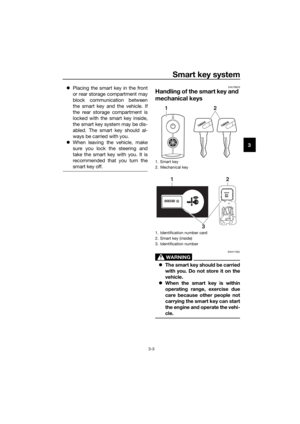 17
17 18
18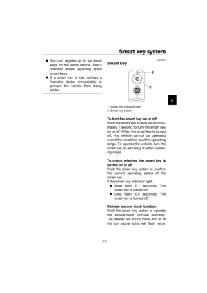 19
19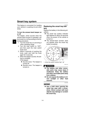 20
20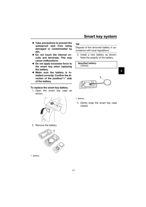 21
21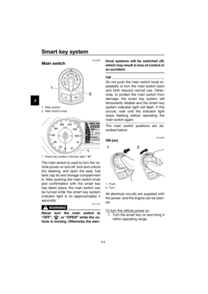 22
22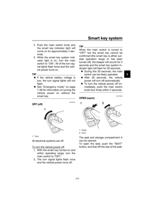 23
23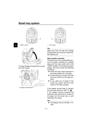 24
24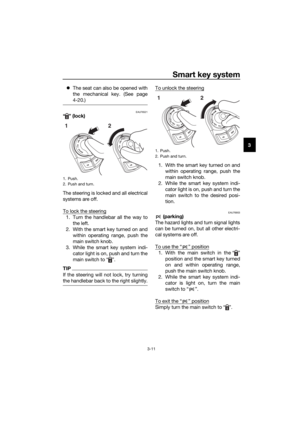 25
25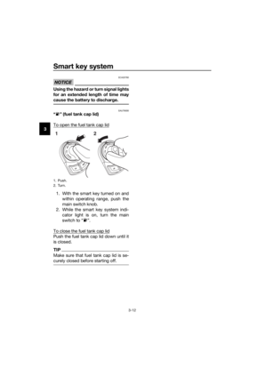 26
26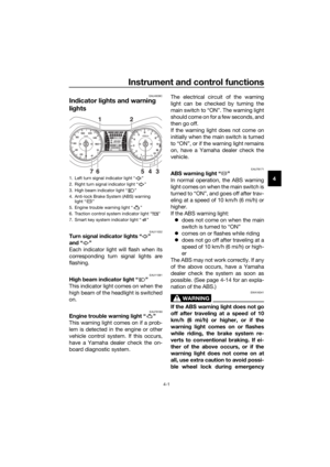 27
27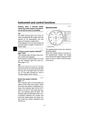 28
28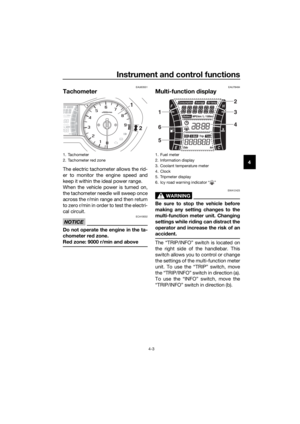 29
29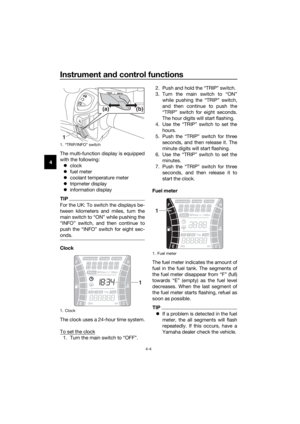 30
30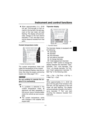 31
31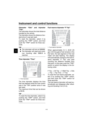 32
32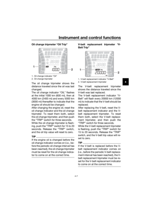 33
33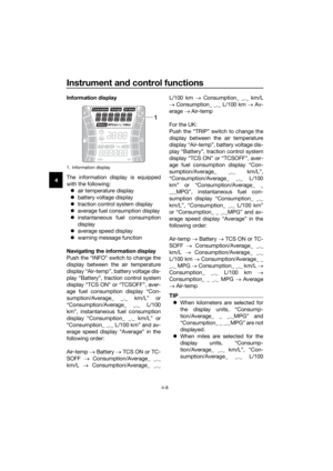 34
34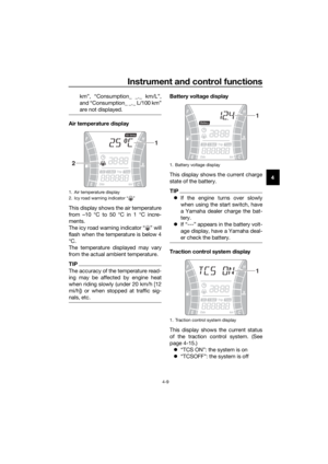 35
35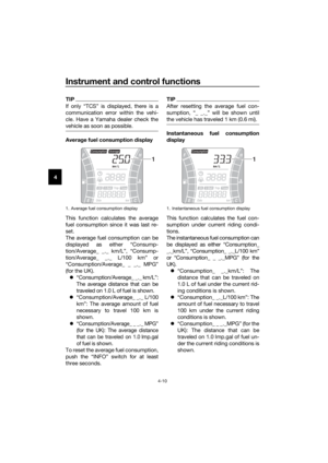 36
36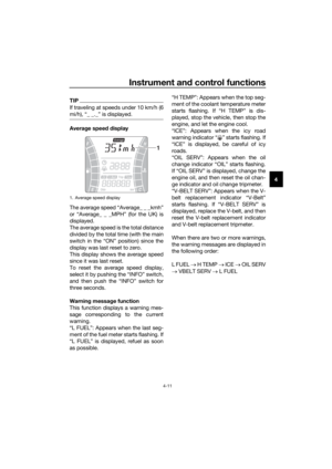 37
37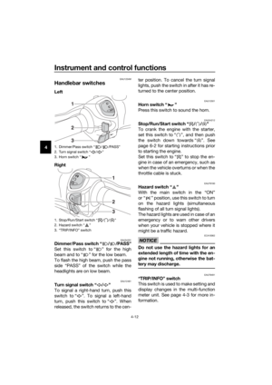 38
38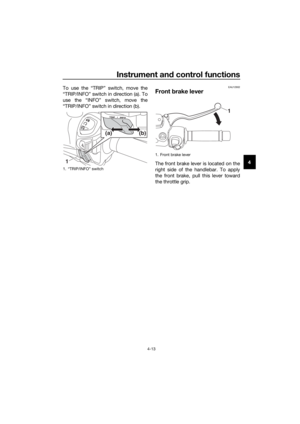 39
39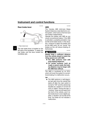 40
40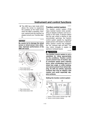 41
41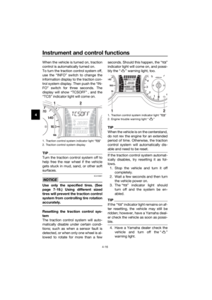 42
42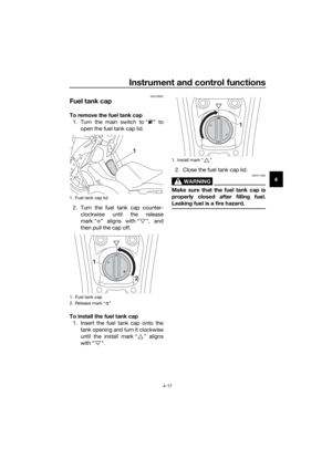 43
43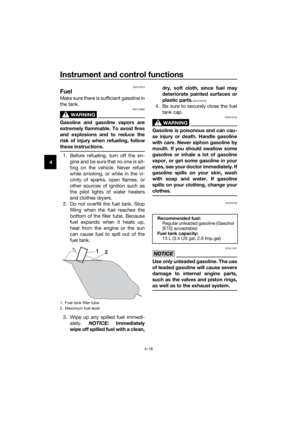 44
44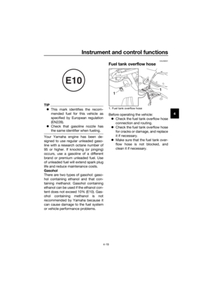 45
45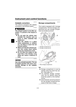 46
46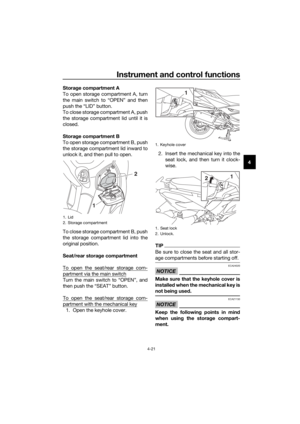 47
47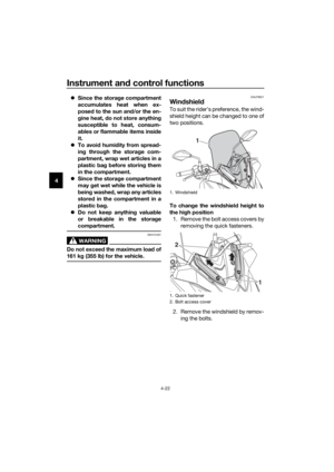 48
48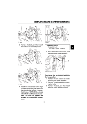 49
49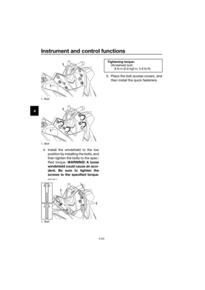 50
50 51
51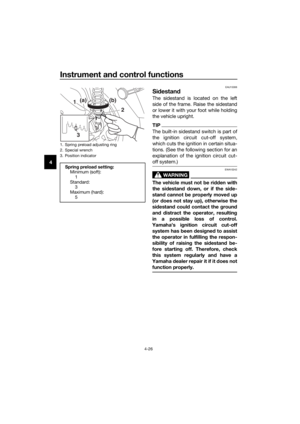 52
52 53
53 54
54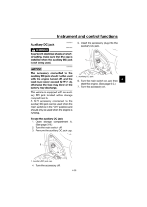 55
55 56
56 57
57 58
58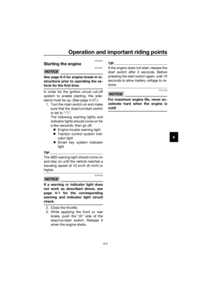 59
59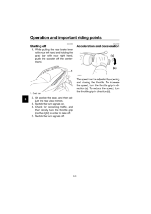 60
60 61
61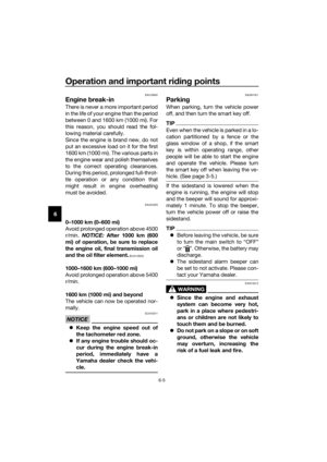 62
62 63
63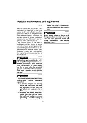 64
64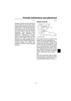 65
65 66
66 67
67 68
68 69
69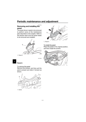 70
70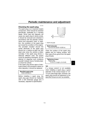 71
71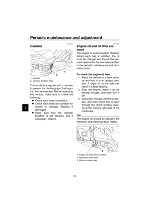 72
72 73
73 74
74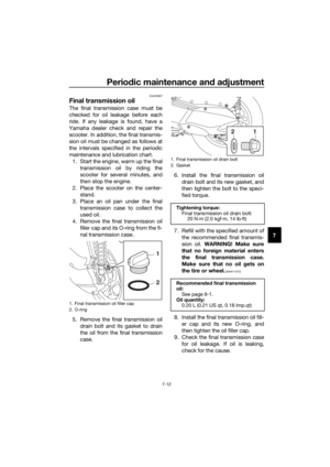 75
75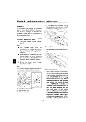 76
76 77
77 78
78 79
79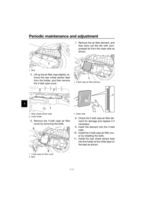 80
80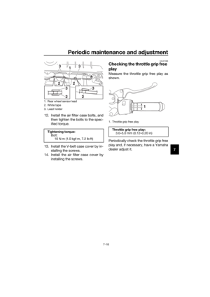 81
81 82
82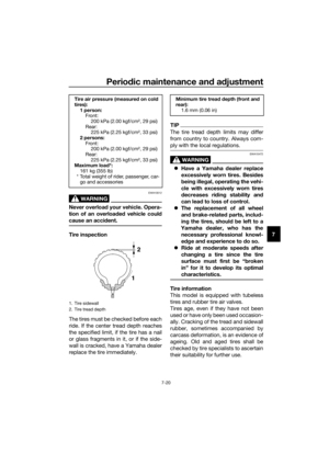 83
83 84
84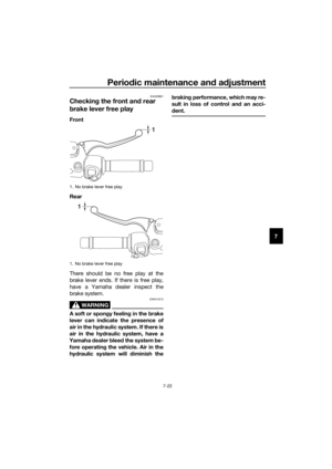 85
85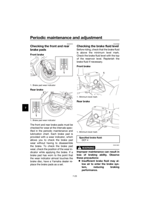 86
86 87
87 88
88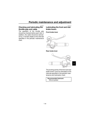 89
89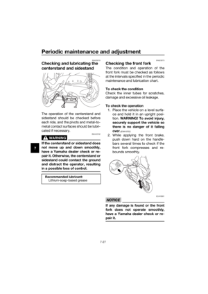 90
90 91
91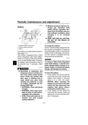 92
92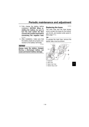 93
93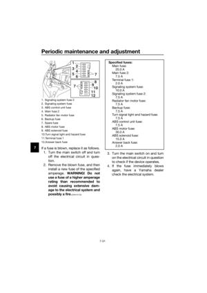 94
94 95
95 96
96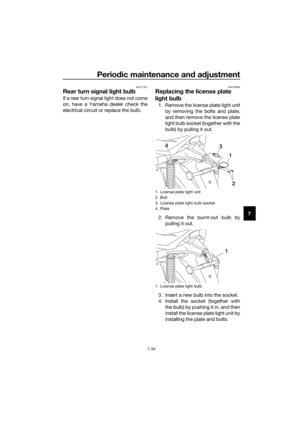 97
97 98
98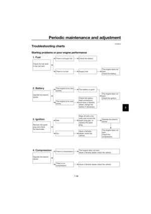 99
99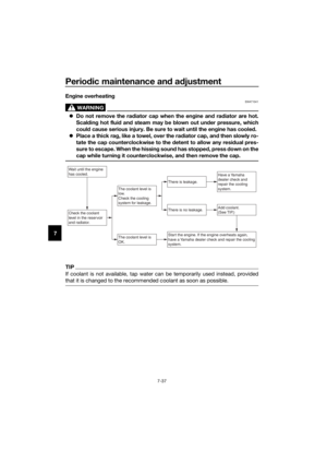 100
100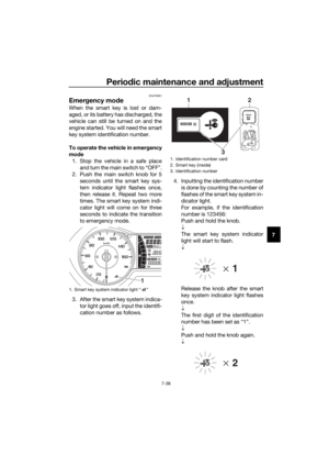 101
101 102
102 103
103 104
104 105
105 106
106 107
107 108
108 109
109 110
110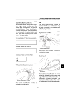 111
111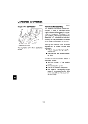 112
112 113
113 114
114 115
115

