2017 YAMAHA XMAX 300 warning
[x] Cancel search: warningPage 27 of 116

Instrument and control functions
4-1
4
EAU4939C
In dicator li ghts an d warnin g
li g hts
EAU11032Turn si gnal in dicator li ghts “ ”
an d“”
Each indicator light will flash when its
corresponding turn signal lights are
flashing.
EAU11081Hi gh beam in dicator li ght “ ”
This indicator light comes on when the
high beam of the headlight is switched
on.
EAU78180En gine trou ble warnin g lig ht “ ”
This warning light comes on if a prob-
lem is detected in the engine or other
vehicle control system. If this occurs,
have a Yamaha dealer check the on-
board diagnostic system. The electrical circuit of the warning
light can be checked by turning the
main switch to “ON”. The warning light
should come on for a few seconds, and
then go off.
If the warning light does not come on
initially when the main switch is turned
to “ON”, or if the warning light remains
on, have a Yamaha dealer check the
vehicle.
EAU78171ABS warnin
g lig ht “ ”
In normal operation, the ABS warning
light comes on when the main switch is
turned to “ON”, and goes off after trav-
eling at a speed of 10 km/h (6 mi/h) or
higher.
If the ABS warning light: �z does not come on when the main
switch is turned to “ON”
�z comes on or flashes while riding
�z does not go off after traveling at a
speed of 10 km/h (6 mi/h) or high-
er
The ABS may not work correctly. If any
of the above occurs, have a Yamaha
dealer check the system as soon as
possible. (See page 4-14 for an expla-
nation of the ABS.)
WARNING
EWA16041
If the ABS warnin g li ght does not go
off after travelin g at a speed of 10
km/h (6 mi/h) or hi gher, or if the
warnin g lig ht comes on or flashes
while ri din g, the b rake system re-
verts to conventional brakin g. If ei-
ther of the a bove occurs, or if the
warnin g lig ht does not come on at
all, use extra caution to avoi d possi-
b le wheel lock durin g emer gency
1. Left turn signal indicator light “ ”
2. Right turn signal indicator light “ ”
3. High beam indicator light “ ”
4. Anti-lock Brake System (ABS) warning
light “ ”
5. Engine trouble warning light “ ”
6. Traction control system indicator light “ ”
7. Smart key system indicator light “ ”
12
36745
ABS
ABS
UB74E0E0.book Page 1 Tuesday, May 2, 2017 1:04 PM
Page 28 of 116

Instrument and control functions
4-2
4 b
rakin g. Have a Yamaha dealer
check the brake system an d electri-
cal circuits as soon as possi ble.
TIP
The ABS warning light may come on
while accelerating the engine with the
vehicle on its centerstand, but this
does not indicate a malfunction.
If this happens, turn the main switch off
and then back on again to reset the in-
dicator light.
EAU78591Traction control system in dicator
li g ht “TCS”
This indicator light will flash when trac-
tion control has engaged.
If the traction control system is turned
off, this indicator light will come on.
(See page 4-15.)
TIP
When the vehicle is turned on, the light
should come on for a few seconds and
then go off. If the light does not come
on, or if the light remains on, have a
Yamaha dealer check vehicle.
EAU78600Smart key system in dicator
li g ht “ ”
This indicator light communicates the
status of the smart key system. When
the smart key system is operating nor-
mally, this indicator light will be off. If
there is an error in the smart key sys-
tem, the indicator light will flash. The
indicator light will also flash when com-
munication between the vehicle and
smart key takes place and when cer-
tain smart key system operations are
carried out.
EAU63542
Spee dometer
The speedometer shows the vehicle's
traveling speed.
When the vehicle power is turned on,
the speedometer needle will sweep
once across the speed range and then
return to zero in order to test the elec-
trical circuit.
1. Speedometer
1
UB74E0E0.book Page 2 Tuesday, May 2, 2017 1:04 PM
Page 29 of 116

Instrument and control functions
4-3
4
EAU63551
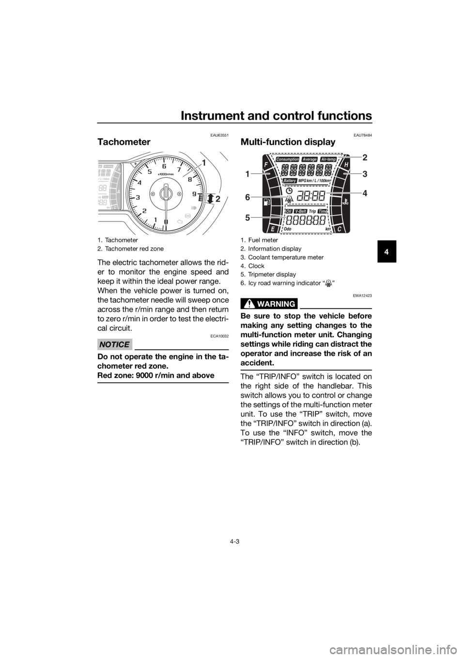
Tachometer
The electric tachometer allows the rid-
er to monitor the engine speed and
keep it within the ideal power range.
When the vehicle power is turned on,
the tachometer needle will sweep once
across the r/min range and then return
to zero r/min in order to test the electri-
cal circuit.
NOTICE
ECA10032
Do not operate the en gine in the ta-
chometer red zone.
Re d zone: 9000 r/min an d a bove
EAU78484
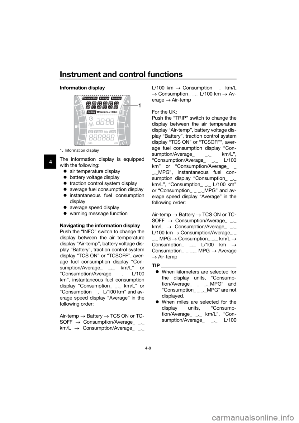
Multi-function d isplay
WARNING
EWA12423
Be sure to stop the vehicle before
makin g any settin g chan ges to the
multi-function meter unit. Chang ing
settin gs while ri din g can d istract the
operator an d increase the risk of an
acci dent.
The “TRIP/INFO” switch is located on
the right side of the handlebar. This
switch allows you to control or change
the settings of the multi-function meter
unit. To use the “TRIP” switch, move
the “TRIP/INFO” switch in direction (a).
To use the “INFO” switch, move the
“TRIP/INFO” switch in direction (b).
1. Tachometer
2. Tachometer red zone
1
2
1. Fuel meter
2. Information display
3. Coolant temperature meter
4. Clock
5. Tripmeter display
6. Icy road warning indicator “ ”
2
3
4
1
6
5
UB74E0E0.book Page 3 Tuesday, May 2, 2017 1:04 PM
Page 34 of 116

Instrument and control functions
4-8
4 Information
display
The information display is equipped
with the following: �z air temperature display
�z battery voltage display
�z traction control system display
�z average fuel consumption display
�z instantaneous fuel consumption
display
�z average speed display
�z warning message function
Navi gatin g the information display
Push the “INFO” switch to change the
display between the air temperature
display “Air-temp”, battery voltage dis-
play “Battery”, traction control system
display “TCS ON” or “TCSOFF”, aver-
age fuel consumption display “Con-
sumption/Average_ _._ km/L” or
“Consumption/Average_ _._ L/100
km”, instantaneous fuel consumption
display “Consumption_ _._ km/L” or
“Consumption_ _._ L/100 km” and av-
erage speed display “Average” in the
following order:
Air-temp → Battery → TCS ON or TC-
SOFF → Consumption/Average_ _._
km/L → Consumption/Average_ _._ L/100 km →
Consumption_ _._ km/L
→ Consumption_ _._ L/100 km → Av-
erage → Air-temp
For the UK:
Push the “TRIP” switch to change the
display between the air temperature
display “Air-temp”, battery voltage dis-
play “Battery”, traction control system
display “TCS ON” or “TCSOFF”, aver-
age fuel consumption display “Con-
sumption/Average_ _._ km/L”,
“Consumption/Average_ _._ L/100
km” or “Consumption/Average_ _
_._MPG”, instantaneous fuel con-
sumption display “Consumption_ _._
km/L”, “Consumption_ _._ L/100 km”
or “Consumption_ _ _._MPG” and av-
erage speed display “Average” in the
following order:
Air-temp → Battery → TCS ON or TC-
SOFF → Consumption/Average_ _._
km/L → Consumption/Average_ _._
L/100 km → Consumption/Average_ _
_._ MPG → Consumption_ _._ km/L →
Consumption_ _._ L/100 km →
Consumption_ _ _._ MPG → Average
→ Air-temp
TIP
�z When kilometers are selected for
the display units, “Consump-
tion/Average_ _ _._MPG” and
“Consumption_ _ _._MPG” are not
displayed.
�z When miles are selected for the
display units, “Consump-
tion/Average_ _._ km/L”, “Con-
sumption/Average_ _._ L/100
1. Information display
1
UB74E0E0.book Page 8 Tuesday, May 2, 2017 1:04 PM
Page 35 of 116

Instrument and control functions
4-9
4
km”, “Consumption_ _._ km/L”,
and “Consumption_ _._ L/100 km”
are not displayed.
Air temperature
display
This display shows the air temperature
from –10 °C to 50 °C in 1 °C incre-
ments.
The icy road warning indicator “ ” will
flash when the temperature is below 4
°C.
The temperature displayed may vary
from the actual ambient temperature.
TIP
The accuracy of the temperature read-
ing may be affected by engine heat
when riding slowly (under 20 km/h [12
mi/h]) or when stopped at traffic sig-
nals, etc.
Battery volta ge display
This display shows the current charge
state of the battery.
TIP
�z If the engine turns over slowly
when using the start switch, have
a Yamaha dealer charge the bat-
tery.
�z If “---” appears in the battery volt-
age display, have a Yamaha deal-
er check the battery.
Traction control system display
This display shows the current status
of the traction control system. (See
page 4-15.) �z “TCS ON”: the system is on
�z “TCSOFF”: the system is off
1. Air temperature display
2. Icy road warning indicator “ ”
1
21. Battery voltage display
1. Traction control system display
1
1
UB74E0E0.book Page 9 Tuesday, May 2, 2017 1:04 PM
Page 37 of 116

Instrument and control functions
4-11
4
TIP
If traveling at speeds under 10 km/h (6
mi/h), “_ _._” is displayed.
Avera ge speed d isplay
The average speed “Average_ _ _kmh”
or “Average_ _ _MPH” (for the UK) is
displayed.
The average speed is the total distance
divided by the total time (with the main
switch in the “ON” position) since the
display was last reset to zero.
This display shows the average speed
since it was last reset.
To reset the average speed display,
select it by pushing the “INFO” switch,
and then push the “INFO” switch for
three seconds.
Warnin g messa ge function
This function displays a warning mes-
sage corresponding to the current
warning.
“L FUEL”: Appears when the last seg-
ment of the fuel meter starts flashing. If
“L FUEL” is displayed, refuel as soon
as possible. “H TEMP”: Appears when the top seg-
ment of the coolant temperature meter
starts flashing. If “H TEMP” is dis-
played, stop the vehicle, then stop the
engine, and let the engine cool.
“ICE”: Appears when the icy road
warning indicator “ ” starts flashing. If
“ICE” is displayed, be careful of icy
roads.
“OIL SERV”: Appears when the oil
change indicator “OIL” starts flashing.
If “OIL SERV” is displayed, change the
engine oil, and then reset the oil chan-
ge indicator and oil change tripmeter.
“V-BELT SERV”: Appears when the V-
belt replacement indicator “V-Belt”
starts flashing. If “V-BELT SERV” is
displayed, replace the V-belt, and then
reset the V-belt replacement indicator
and V-belt replacement tripmeter.
When there are two or more warnings,
the warning messages are displayed in
the following order:
L FUEL
→ H TEMP → ICE → OIL SERV
→ VBELT SERV → L FUEL
1. Average speed display
1
UB74E0E0.book Page 11 Tuesday, May 2, 2017 1:04 PM
Page 40 of 116

Instrument and control functions
4-14
4
EAU12952
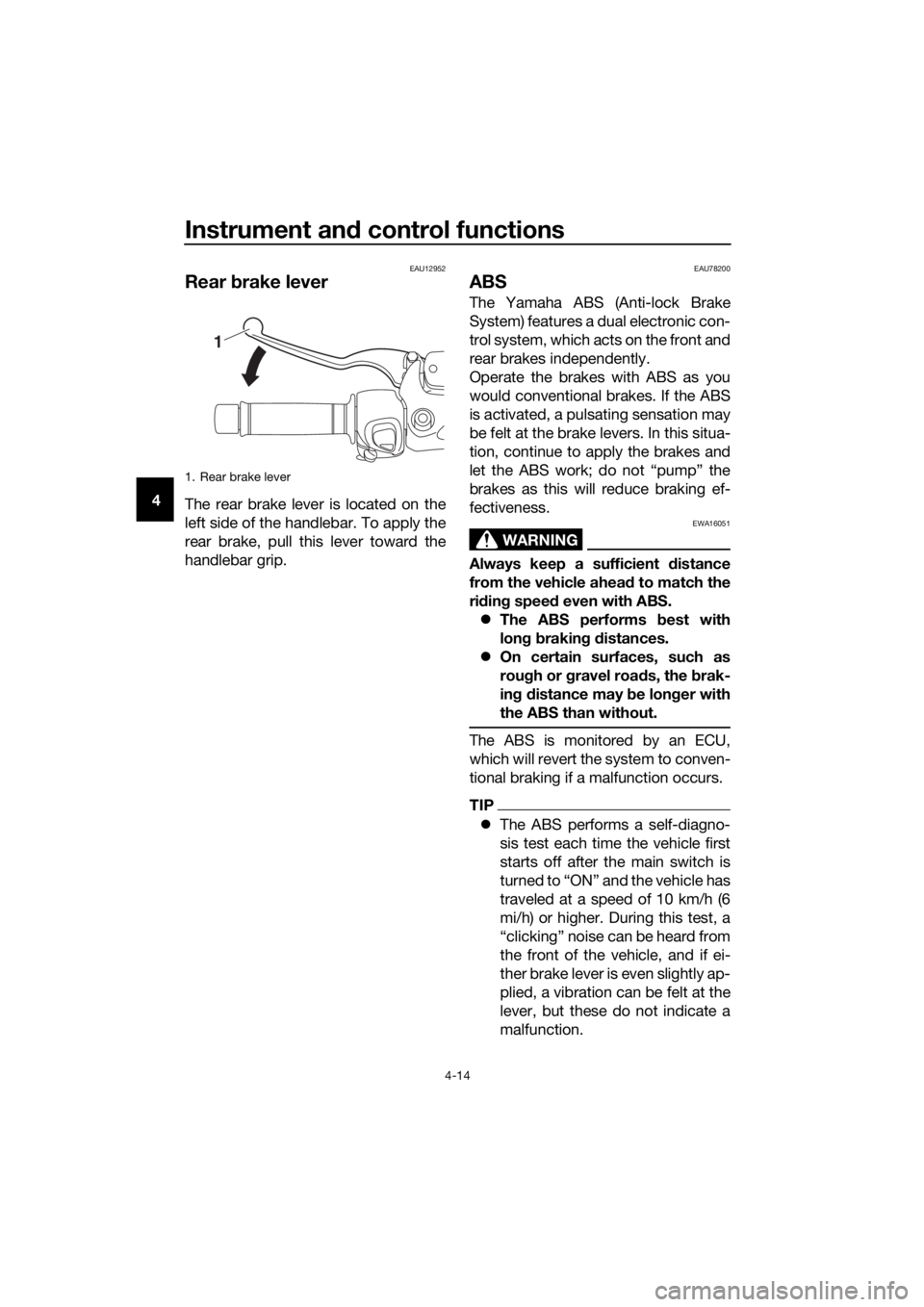
Rear brake lever
The rear brake lever is located on the
left side of the handlebar. To apply the
rear brake, pull this lever toward the
handlebar grip.
EAU78200
ABS
The Yamaha ABS (Anti-lock Brake
System) features a dual electronic con-
trol system, which acts on the front and
rear brakes independently.
Operate the brakes with ABS as you
would conventional brakes. If the ABS
is activated, a pulsating sensation may
be felt at the brake levers. In this situa-
tion, continue to apply the brakes and
let the ABS work; do not “pump” the
brakes as this will reduce braking ef-
fectiveness.
WARNING
EWA16051
Always keep a sufficient d istance
from the vehicle ahead to match the
ri din g speed even with ABS.
�z The ABS performs b est with
lon g b rakin g d istances.
�z On certain surfaces, such as
rou gh or g ravel roa ds, the b rak-
in g d istance may be lon ger with
the ABS than without.
The ABS is monitored by an ECU,
which will revert the system to conven-
tional braking if a malfunction occurs.
TIP
�z The ABS performs a self-diagno-
sis test each time the vehicle first
starts off after the main switch is
turned to “ON” and the vehicle has
traveled at a speed of 10 km/h (6
mi/h) or higher. During this test, a
“clicking” noise can be heard from
the front of the vehicle, and if ei-
ther brake lever is even slightly ap-
plied, a vibration can be felt at the
lever, but these do not indicate a
malfunction.
1. Rear brake lever
1
UB74E0E0.book Page 14 Tuesday, May 2, 2017 1:04 PM
Page 41 of 116

Instrument and control functions
4-15
4
�z
This ABS has a test mode which
allows the owner to experience
the pulsation at the brake levers
when the ABS is operating. How-
ever, special tools are required, so
please consult your Yamaha deal-
er.
NOTICE
ECA20100
Be careful not to damag e the wheel
sensor or wheel sensor rotor; other-
wise, improper performance of the
ABS will result.
EAU78611
Traction control system
The traction control system (TCS)
helps maintain traction when acceler-
ating on slippery surfaces, such as un-
paved or wet roads. If sensors detect
that the rear wheel is starting to slip
(uncontrolled spinning), the traction
control system assists by regulating
engine power until traction is restored.
When traction control has engaged,
the “ ” indicator light will flash. You
may notice changes in engine re-
sponse or exhaust sound.
WARNING
EWA18860
The traction control system is not a
su bstitute for ri din g appropriately
for the con ditions. Traction control
cannot prevent loss of traction d ue
to excessive spee d when enterin g
turns, when acceleratin g har d at a
sharp lean an gle, or while b raking,
an d cannot prevent front wheel slip-
pin g. As with any vehicle, approach
surfaces that may be slippery with
caution an d avoi d especially slip-
pery surfaces.
Settin g the traction control system
1. Front wheel sensor
2. Front wheel sensor rotor
1. Rear wheel sensor
2. Rear wheel sensor rotor
2
1
2
1
1. Traction control system indicator light “ ”
2. Traction control system display
12
UB74E0E0.book Page 15 Tuesday, May 2, 2017 1:04 PM