Page 191 of 432

HANDLEBAR
5-37
▲▲▲▲▲▲▲▲▲▲▲▲▲▲▲▲▲▲▲▲▲▲▲▲▲▲▲▲▲▲▲▲
5. Install:
• Engine stop switch “1”
• Clutch lever “2”
• Clutch lever holder “3”
•Clamp “4”
TIP
• The engine stop switch, the clutch lever, and
the clutch lever holder should be installed ac-
cording to the dimensions shown.
• Pass the engine stop switch lead through the
middle of the clutch lever holder.
6. Install:
• Right grip “1”
• Collar “2”
Apply adhesive to the tube guide “3”.
TIP
• Before applying the adhesive, wipe off grease
or oil on the tube guide surface “a” with a lac-
quer thinner.
• Install the grip to the tube guide so that the
grip match mark “b” and tube guide slot “c”
form the angle as shown.7. Install:
• Rubber cover “1”
• Throttle grip “2”
TIP
Apply the lithium-soap-based grease on the
throttle grip sliding surface.
8. Install:
• Throttle cables “1”
TIP
Slightly coat the end of throttle cable and inside
of throttle grip with lithium-soap-based grease.
Then, mount the throttle grip onto the handle-
bar. Engine stop switch screw
0.5 Nm (0.05 m·kgf, 0.36 ft·lbf)
Clutch lever holder bolt
3.8 Nm (0.38 m·kgf, 2.8 ft·lbf)
T R..
64
1b
c
3 64
Page 207 of 432

STEERING HEAD
5-53
EAS2GBB203
STEERING HEAD
Removing the lower bracket
Order Part name Q’ty Remarks
Refer to “CHECKING AND ADJUSTING
THE STEERING HEAD” on page 3-37.
Use a suitable stand to raise the front wheel
off the ground.
Headlight assembly/multi-function meter/front
fenderRefer to “GENERAL CHASSIS” on page 5-1.
Handlebar Refer to “HANDLEBAR” on page 5-33.
1 Front fender 1
2 Steering stem nut 1
3 Front fork leg (s) 2 Refer to “FRONT FORK” on page 5-40.
4 Upper bracket 1
5 Steering ring nut 1
6 Lower bracket 1
7 Bearing race cover 1
8 Upper bearing 1
9 Bearing (lower side) 1
10 Bearing races 2
2
4
5
7
3
(2)(2)
(2)
(2) (2)
1
6
8
9
10
LS
LS
T
.R.21 Nm (2.1 mlbf) kgf, 15 ft
T
.R.21 Nm (2.1 mlbf) kgf, 15 ft
T
.R.21 Nm (2.1 mlbf) kgf, 15 ft
T
.R.21 Nm (2.1 mlbf) kgf, 15 ft
T
.R.3.8 Nm (0.38 mlbf) kgf, 2.8 ft
T
.R.3.8 Nm (0.38 mlbf) kgf, 2.8 ft
T
.R.9 Nm (0.9 mlbf) kgf, 6.5 ft
T
.R.7 Nm (0.7 mlbf) kgf, 5.1 ftT
.R.7 Nm (0.7 mlbf) kgf, 5.1 ft
T
.R.10 Nm (1.0 mlbf) kgf, 7.2 ft
T
.R.145 Nm (14.5 mlbf) kgf, 105 ft
T
.R.38 Nm (3.8 mlbf) kgf, 27 ft
7 Nm (0.7 m
lbf) kgf, 5.1 ft
*
*
Page 236 of 432

ENGINE REMOVAL
6-7
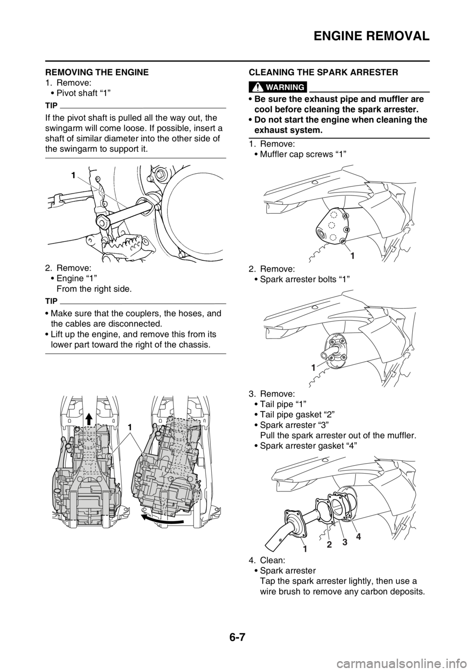
EAS2GBB230REMOVING THE ENGINE
1. Remove:
• Pivot shaft “1”
TIP
If the pivot shaft is pulled all the way out, the
swingarm will come loose. If possible, insert a
shaft of similar diameter into the other side of
the swingarm to support it.
2. Remove:
• Engine “1”
From the right side.
TIP
• Make sure that the couplers, the hoses, and
the cables are disconnected.
• Lift up the engine, and remove this from its
lower part toward the right of the chassis.
EAS2GBB231CLEANING THE SPARK ARRESTEREWA
WARNING
• Be sure the exhaust pipe and muffler are
cool before cleaning the spark arrester.
• Do not start the engine when cleaning the
exhaust system.
1. Remove:
• Muffler cap screws “1”
2. Remove:
• Spark arrester bolts “1”
3. Remove:
• Tail pipe “1”
• Tail pipe gasket “2”
• Spark arrester “3”
Pull the spark arrester out of the muffler.
• Spark arrester gasket “4”
4. Clean:
• Spark arrester
Tap the spark arrester lightly, then use a
wire brush to remove any carbon deposits.
1
Page 245 of 432

CAMSHAFT
6-16
c. Install the dowel pins and the camshaft
caps.
TIP
• Tighten the camshaft cap bolts in a crisscross
pattern from innermost to outer caps.
• Do not turn the camshaft when measuring the
camshaft journal-to-camshaft cap clearance.
d. Remove the camshaft caps and then mea-
sure the width of the Plastigauge® “1”.
▲▲▲▲▲▲▲▲▲▲▲▲▲▲▲▲▲▲▲▲▲▲▲▲▲▲▲▲▲▲▲▲
5. Measure:
• Camshaft journal diameter “a”
Out of specification Replace the cam-
shaft.
Within specification Replace the cylinder
head and the camshaft caps as a set.
EAS2GBB240CHECKING THE TIMING CHAIN AND CAM-
SHAFT SPROCKET
1. Check:
•Timing chain
Damage/stiffness Replace the timing
chain and camshaft as a set.2. Check:
• Camshaft sprocket
More than 1/4 tooth wear “a” Replace the
camshaft and the timing chain as a set.
EAS2GBB241CHECKING THE TIMING CHAIN TENSION-
ERS
1. Check:
• Timing chain tensioner
Crack/damage Replace.
▼▼▼▼▼▼▼▼▼▼▼▼▼▼▼▼▼▼▼▼▼▼▼▼▼▼▼▼▼▼▼▼
a. While pressing the tensioner rod lightly with
your fingers, use a thin screwdriver “1” to
wind the tensioner rod up fully clockwise.
b. When releasing the screwdriver by pressing
lightly with your fingers, make sure that the
tensioner rod will come out smoothly.
c. If not, replace the tensioner assembly.
▲▲▲▲▲▲▲▲▲▲▲▲▲▲▲▲▲▲▲▲▲▲▲▲▲▲▲▲▲▲▲▲
Camshaft cap bolts
10 Nm (1.0 m·kgf, 7.2 ft·lbf)
Camshaft journal diameter
21.959–21.972 mm (0.8645–
0.8650 in)
T R..
1
a. 1/4 tooth
b. Correct
1. Timing chain roller
2. Camshaft sprocket
a
b1
2
Page 247 of 432

CAMSHAFT
6-18
ECA33DD030
NOTICE
The bolts (camshaft cap) must be tightened
evenly, or damage to the cylinder head,
camshaft caps, and camshaft will result.
▲▲▲▲▲▲▲▲▲▲▲▲▲▲▲▲▲▲▲▲▲▲▲▲▲▲▲▲▲▲▲▲
2. Install:
• Timing chain tensioner
▼▼▼▼▼▼▼▼▼▼▼▼▼▼▼▼▼▼▼▼▼▼▼▼▼▼▼▼▼▼▼▼
a. While pressing the tensioner rod lightly with
your fingers, use a thin screwdriver to wind
the tensioner rod up fully clockwise.
b. With the tensioner rod fully wound and the
chain tensioner UP mark “a” facing upward,
install the gasket “1” and the timing chain
tensioner “2” and tighten the bolt “3”.c. Release the screwdriver, check that the ten-
sioner rod comes out smoothly, and tighten
the gasket “4” and the cap bolt “5”.
▲▲▲▲▲▲▲▲▲▲▲▲▲▲▲▲▲▲▲▲▲▲▲▲▲▲▲▲▲▲▲▲
3. Turn:
• Crankshaft
Counterclockwise several turns.
4. Check:
• Top dead center (TDC) mark on the rotor
Align with the crankcase alignment mark.
• Camshaft match marks
Align with the cylinder head surface.
Out of alignment Adjust.
5. Install:
• Timing chain guide (top side) “1”
• Cylinder head cover gasket “2”
• Cylinder head cover “3”
• Bolt (cylinder head cover) “4”
TIP
Before installation, apply the sealant to the cyl-
inder head cover gasket. Bolt (timing chain tensioner)
10 Nm (1.0 m·kgf, 7.2 ft·lbf)
3
4
8
7
15
26
E
T R..
Tensioner cap bolt
6 Nm (0.6 m·kgf, 4.3 ft·lbf)
Bolt (cylinder head cover)
10 Nm (1.0 m·kgf, 7.2 ft·lbf)
Yamaha bond No.1215
90890-85505
(Three bond No.1215®)
T R..
4
5
T R..
4
4
3
21
Page 259 of 432

VALVES AND VALVE SPRINGS
6-30
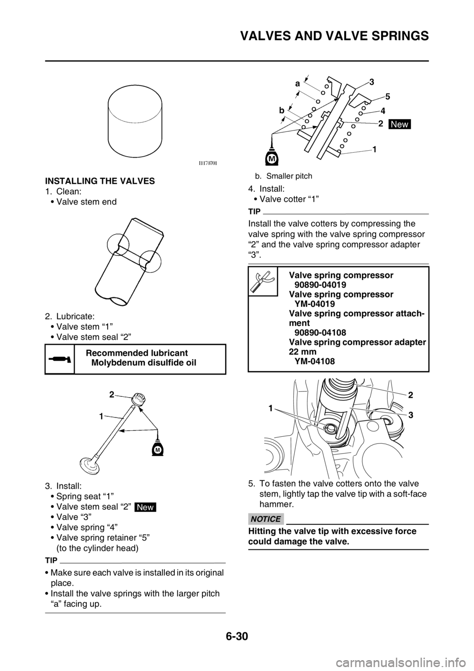
EAS2GBB255INSTALLING THE VALVES
1. Clean:
• Valve stem end
2. Lubricate:
• Valve stem “1”
• Valve stem seal “2”
3. Install:
• Spring seat “1”
• Valve stem seal “2”
•Valve “3”
• Valve spring “4”
• Valve spring retainer “5”
(to the cylinder head)
TIP
• Make sure each valve is installed in its original
place.
• Install the valve springs with the larger pitch
“a” facing up.4. Install:
• Valve cotter “1”
TIP
Install the valve cotters by compressing the
valve spring with the valve spring compressor
“2” and the valve spring compressor adapter
“3”.
5. To fasten the valve cotters onto the valve
stem, lightly tap the valve tip with a soft-face
hammer.
ECA
NOTICE
Hitting the valve tip with excessive force
could damage the valve. Recommended lubricant
Molybdenum disulfide oil
New
b. Smaller pitch
Valve spring compressor
90890-04019
Valve spring compressor
YM-04019
Valve spring compressor attach-
ment
90890-04108
Valve spring compressor adapter
22 mm
YM-04108
Page 304 of 432

CRANKCASE
6-75
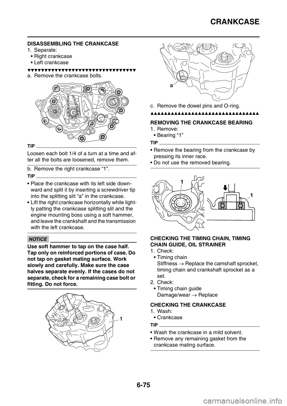
EAS2GBB311DISASSEMBLING THE CRANKCASE
1. Separate:
• Right crankcase
• Left crankcase
▼▼▼▼▼▼▼▼▼▼▼▼▼▼▼▼▼▼▼▼▼▼▼▼▼▼▼▼▼▼▼▼
a. Remove the crankcase bolts.
TIP
Loosen each bolt 1/4 of a turn at a time and af-
ter all the bolts are loosened, remove them.
b. Remove the right crankcase “1”.
TIP
• Place the crankcase with its left side down-
ward and split it by inserting a screwdriver tip
into the splitting slit “a” in the crankcase.
• Lift the right crankcase horizontally while light-
ly patting the crankcase splitting slit and the
engine mounting boss using a soft hammer,
and leave the crankshaft and the transmission
with the left crankcase.
ECA
NOTICE
Use soft hammer to tap on the case half.
Tap only on reinforced portions of case. Do
not tap on gasket mating surface. Work
slowly and carefully. Make sure the case
halves separate evenly. If the cases do not
separate, check for a remaining case bolt or
fitting. Do not force.c. Remove the dowel pins and O-ring.
▲▲▲▲▲▲▲▲▲▲▲▲▲▲▲▲▲▲▲▲▲▲▲▲▲▲▲▲▲▲▲▲
EAS2GBB312REMOVING THE CRANKCASE BEARING
1. Remove:
• Bearing “1”
TIP
• Remove the bearing from the crankcase by
pressing its inner race.
• Do not use the removed bearing.
EAS2GBB313CHECKING THE TIMING CHAIN, TIMING
CHAIN GUIDE, OIL STRAINER
1. Check:
• Timing chain
Stiffness Replace the camshaft sprocket,
timing chain and crankshaft sprocket as a
set.
2. Check:
• Timing chain guide
Damage/wear Replace
EAS2GBB314CHECKING THE CRANKCASE
1. Wash:
• Crankcase
TIP
• Wash the crankcase in a mild solvent.
• Remove any remaining gasket from the
crankcase mating surface.
1
a
Page 305 of 432

CRANKCASE
6-76
2. Check:
• Crankcase
Crack/damage Replace.
• Oil delivery passages
Obstruction Blow out with compressed
air.
EAS2GBB315INSTALLING THE OIL SEAL
1. Install:
• Oil seal “1”
(to left crankcase)
EAS2GBB316ASSEMBLING THE CRANKCASE
1. Install:
• Bearing cover plate screw
TIP
Install the bearing by pressing its outer race
parallel.
2. Apply:
• Sealant
(to the crankcase mating surface)3. Install:
• Oil nozzle “1”
• Dowel pin “2”
• Crankcase “3”
(to the left crankcase)
TIP
• Apply the lithium-soap-based grease on the
O-ring.
• Fit the right crankcase onto the left crankcase.
Tap lightly on the case with soft hammer.
• When installing the crankcase, the connecting
rod should be positioned at top dead center
(TDC).
• Tighten the bolts in a crisscross pattern in two
(2) stages, with 1/4 turn each. Installed depth “a”
4.5–5.0 mm (0.18–0.20 in)
Bearing cover plate screw
12 Nm (1.2 m·kgf, 8.7 ft·lbf)
LOCTITE®
Bearing cover plate screw (crank-
shaft)
22 Nm (2.2 m·kgf, 16 ft·lbf)
LOCTITE®
Yamaha bond No. 1215
90890-85505
(Three bond No.1215®)
New
a 1
T R..
Oil nozzle bolt
5 Nm (0.5 m·kgf, 3.6 ft·lbf)
LOCTITE®
Crankcase bolt
12 Nm (1.2 m·kgf, 8.7 ft·lbf)
T R..
T R..