Page 33 of 106
![YAMAHA VXR 2017 Owners Manual Control function operation
27
will not start. Also, the starter motor could
be damaged.
[ECJ01041]
The engine will not start under any of the fol-
lowing conditions:
Lock mode of the Yamaha Securi](/manual-img/51/52184/w960_52184-32.png "YAMAHA VXR 2017 Owners Manual Control function operation
27
will not start. Also, the starter motor could
be damaged.
[ECJ01041]
The engine will not start under any of the fol-
lowing conditions:
Lock mode of the Yamaha Securi")
Control function operation
27
will not start. Also, the starter motor could
be damaged.
[ECJ01041]
The engine will not start under any of the fol-
lowing conditions:
Lock mode of the Yamaha Security System
has been selected. (See page 25 for
Yamaha Security System setting proce-
dures.)
Clip is removed from the engine shut-off
switch.
Throttle lever is squeezed.
Throttle lever is malfunctioning.
RiDE lever is squeezed.
RiDE lever is malfunctioning.EJU31212Throttle lever
The throttle lever increases the engine speed
when the lever is squeezed.
The throttle lever returns automatically to its
fully closed (idle) position when released.
EJU43342RiDE lever
When the RiDE lever is squeezed, the reverse
gate lowers and the watercraft starts moving
in reverse. If the watercraft is moving forward,
the watercraft gradually slows down until it
stops, and then the watercraft starts moving
in reverse.
When the RiDE lever is released, it automati-
cally returns to its fully closed (idle) position
and the reverse gate moves to the neutral po-
sition.
EJU31262Steering system
By turning the handlebars in the direction you
wish to travel, the angle of the jet thrust noz-
1Start switch
1Throttle lever
1
1
1RiDE lever
1
UF2W73E0.book Page 27 Tuesday, August 2, 2016 10:10 AM
Page 34 of 106

Control function operation
28
zle is changed, and the direction of the water-
craft is changed accordingly.
Since the strength of the jet thrust determines
the speed and degree of a turn, throttle must
always be applied when attempting a turn,
except at trolling speed.
This model is equipped with the Yamaha En-
gine Management System (YEMS) that in-
cludes an off-throttle steering (OTS) system.
It will activate at planing speeds should you
attempt to steer the watercraft after releasing
the throttle lever. The OTS system assists in
turning by continuing to supply some thrust
while the watercraft is decelerating, but you
can turn more sharply if you apply throttle
while turning the handlebars. The OTS sys-
tem does not function below planing speeds
or when the engine is off. Once the engine
slows down, the watercraft will no longer turn
in response to handlebar input until you apply
throttle again or you reach trolling speed.EJU35975Cooling water pilot outlet
When the engine is running, some of the
cooling water that is circulated in the engine
is discharged from the cooling water pilot
outlet.
There is a cooling water pilot outlet on the
port (left) side of the watercraft. To check for
proper operation of the cooling system, make
sure that water is being discharged from the
cooling water pilot outlet. If water is not being
discharged from the outlet, stop the engine
and check the jet intake for clogging. (See
page 91 for information on the jet intake.)
TIP:
It will take about 60 seconds for the water
to reach the outlet after the engine is start-
ed.
Water discharge may not be constant
when the engine is running at idling speed.
If this occurs, apply a little throttle to make
sure that water discharges properly.
EJU40323Water separator
The water separator prevents water from en-
tering the fuel tank by collecting any water
that has entered the fuel tank breather hose if
the watercraft was capsized.
1Handlebar
2Jet thrust nozzle
1
21Cooling water pilot outlet
1
UF2W73E0.book Page 28 Tuesday, August 2, 2016 10:10 AM
Page 35 of 106
Control function operation
29
If water has collected in the water separator,
drain it by loosening the drain screw.
To drain water from the water separator:
(1) Place a drain pan or dry cloth under the
water separator.
(2) Gradually loosen the drain screw to drain
the water. Catch the draining water in the
drain pan or soak it up with the dry cloth
so that it does not spill into the engine
compartment. If any water spills into the
watercraft, be sure to wipe it up with a
dry cloth.
(3) Securely tighten the drain screw until it
stops.
1Water separator
2Drain screw
2
1
UF2W73E0.book Page 29 Tuesday, August 2, 2016 10:10 AM
Page 36 of 106

Watercraft operation
30
EJU40014
Watercraft operation functions
EJU43154Shift system
WARNING
EWJ01773
Make sure that there are no obstacles or
people behind you before shifting into
reverse.
Do not touch the reverse gate while the
RiDE lever is being operated, otherwise
you could be pinched.
If the RiDE lever and throttle lever are
being operated at the same time, do not
release only the RiDE lever. Otherwise,
the watercraft could accelerate more
quickly than expected, which may lead
to an accident.
The RiDE lever and throttle lever can be oper-
ated to change the forward or rearward
movement of the watercraft only when the
engine is running. When the RiDE lever is
squeezed, the reverse gate lowers and de-
flects the water jet being discharged from the
jet thrust nozzle so that the watercraft moves
in reverse or is in neutral. When the throttle le-
ver is squeezed, the reverse gate rises and
the watercraft moves forward.
TIP:
This model is equipped with a function
which limits the engine speed in reverse.
When the engine is started, the reverse
gate automatically moves to the neutral po-
sition.
To shift into reverse:
(1) Release the throttle lever.
(2) Squeeze the RiDE lever. The reverse
gate will lower, the engine speed will in-
crease, the watercraft will start moving inreverse, and the “R” (reverse) shift indi-
cator will be displayed.
To shift into neutral from reverse:
Release the RiDE lever. The reverse gate will
automatically return to the neutral position
1RiDE lever
1Reverse gate
2Reverse position
1“R” (Reverse position)
1
1
2
1
UF2W73E0.book Page 30 Tuesday, August 2, 2016 10:10 AM
Page 37 of 106
Watercraft operation
31
and the “N” (neutral) shift indicator will be dis-
played.
TIP:
Although the neutral position helps keep the
watercraft from moving even when the en-
gine is running, some movement may occur.To shift into forward:
(1) Release the RiDE lever.
(2) Squeeze the throttle lever. The reverse
gate will rise completely, the engine
speed will increase, the watercraft will
start moving forward, and the “F” (for-
ward) shift indicator will be displayed.
1RiDE lever
1Reverse gate
2Neutral position
1“N” (Neutral position)
1
1
2
1
1Throttle lever
1Reverse gate
2Forward position
1“F” (Forward position)
1
1
2
1
UF2W73E0.book Page 31 Tuesday, August 2, 2016 10:10 AM
Page 38 of 106

Watercraft operation
32
TIP:
If the RiDE lever is squeezed while the throttle
lever is squeezed, the watercraft will slow
down, and once stopped, move in reverse.
To shift into neutral from forward:
(1) Release the throttle lever.
(2) Lightly squeeze and release the RiDE le-
ver. The “N” (neutral) shift indicator will
be displayed.
TIP:
If the RiDE lever is squeezed continuously,
the reverse gate will move to the reverse po-
sition.
EJU43161Electric trim system
The electric trim up switch and electric trim
down switch are located at the left handlebar
grip and are operated to change the vertical
angle of the jet thrust nozzle, which adjusts
the trim angle of the watercraft. The switchescan be operated only when the engine is run-
ning.
There are 5 positions: neutral, 2 bow-down
positions (a) and (b), and 2 bow-up positions
(c) and (d).
Bow-down positions (a) and (b)
The bow will go down, causing the trim angle
to decrease.
1“N” (Neutral position)
1
1Electric trim up switch
2Electric trim down switch
1
2
(d)
(c)
(b)
(a)
(d)
(c)
(b)
(a)
UF2W73E0.book Page 32 Tuesday, August 2, 2016 10:10 AM
Page 39 of 106
 and (d)
The bow will go up, causing th")
Watercraft operation
33
Vertical movement of the bow will be reduced
and the watercraft will get up on plane more
quickly when accelerating.
Bow-up positions (c) and (d)
The bow will go up, causing the trim angle to
increase.
There is less water resistance, therefore,
straight-ahead acceleration is enhanced.
TIP:
The watercraft performance characteristics
according to the trim angle change depend-
ing on the operating conditions.
To change the trim angle:
(1) If the reverse gate is in the neutral posi-
tion, lightly squeeze the throttle lever so
that the watercraft moves forward.(2) Push the electric trim up switch or elec-
tric trim down switch to select the de-
sired trim angle.
TIP:
When the reverse gate moves to the neutral
or reverse position, the jet thrust nozzle will
automatically return to the neutral position.
When the reverse gate moves to the for-
ward position, the jet thrust nozzle will au-
tomatically change to the set trim angle.
When the engine stops, the jet thrust noz-
zle returns to the neutral position.
(d)
(c)
(b)N
(a)
1Electric trim up switch
2Electric trim down switch
1
2
UF2W73E0.book Page 33 Tuesday, August 2, 2016 10:10 AM
Page 40 of 106

Watercraft operation
34
EJU40001
Watercraft operation modes
EJU36787Low RPM Mode
The Low RPM Mode is a function that limits
the maximum engine speed to approximately
70% of the maximum engine speed in the
normal mode.
The Low RPM Mode can only be activated
and deactivated by operating the remote
control transmitter that is included with this
watercraft. (See page 24 for information on
the remote control transmitter.)
TIP:
The Low RPM Mode can only be activated
when the engine is stopped in the unlock
mode of the Yamaha Security System.
Activating and deactivating the Low RPM
Mode
Activation of the Low RPM Mode will be con-
firmed by the number of beeps when the re-
mote control transmitter is operated, and by
the “L-MODE” indicator light of the multifunc-
tion information center. (See page 36 for in-
formation on the multifunction information
center.)
TIP:
If the remote control transmitter is operated
while the multifunction information center is
in the standby state, the center performs the
initial operation, and then the setting is se-
lected.
To activate the Low RPM Mode:
Push the “L-Mode” (unlock) button on the re-
mote control transmitter for more than 4 sec-
onds. Once the beeper sounds three times
and the “UNLOCK” indicator light blinks
three times, then comes on, the “L-MODE”
indicator light comes on and the Low RPM
Mode is activated.
TIP:
If the Low RPM Mode is activated immediate-
ly after the information display turns off, the
“L-MODE” indicator light will not come on.1Remote control transmitter
Number of
beepsLow RPM Mode
operation“L-
MODE”
indicator
light
ActivatedComes
on
Deactivated Goes off
UF2W73E0.book Page 34 Tuesday, August 2, 2016 10:10 AM
 1
1 2
2 3
3 4
4 5
5 6
6 7
7 8
8 9
9 10
10 11
11 12
12 13
13 14
14 15
15 16
16 17
17 18
18 19
19 20
20 21
21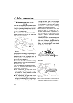 22
22 23
23 24
24 25
25 26
26 27
27 28
28 29
29 30
30 31
31 32
32 33
33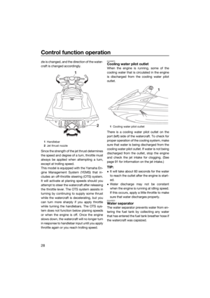 34
34 35
35 36
36 37
37 38
38 39
39 40
40 41
41 42
42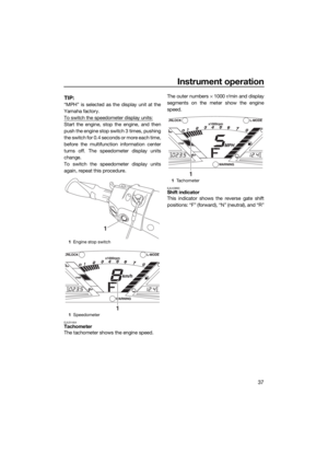 43
43 44
44 45
45 46
46 47
47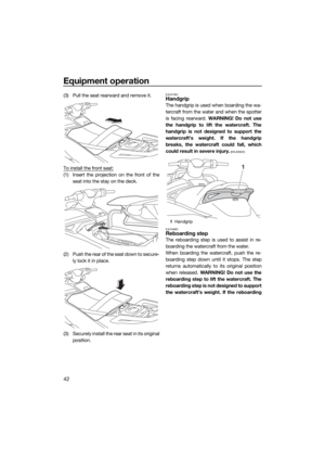 48
48 49
49 50
50 51
51 52
52 53
53 54
54 55
55 56
56 57
57 58
58 59
59 60
60 61
61 62
62 63
63 64
64 65
65 66
66 67
67 68
68 69
69 70
70 71
71 72
72 73
73 74
74 75
75 76
76 77
77 78
78 79
79 80
80 81
81 82
82 83
83 84
84 85
85 86
86 87
87 88
88 89
89 90
90 91
91 92
92 93
93 94
94 95
95 96
96 97
97 98
98 99
99 100
100 101
101 102
102 103
103 104
104 105
105 Place a drain pan or dry cloth under th")
 shift indicator will be dis-
played.
TIP:
Although the neutral position helps keep the
watercraft from moving even when the en-
gine is running, some")