Page 25 of 106

Description
19
EJU43331
Watercraft glossary
Trolling speed
“Trolling” is the lowest maneuvering speed. You are applying little or no throttle. The water-
craft is down in the water, and there is no wake.
Sub-planing speed
“Sub-planing” is a medium speed. The bow of the watercraft is slightly up from the water sur-
face, but you are still traveling through the water. There is a wake.
Planing speed
“Planing” is a faster speed. The watercraft is more level and is skimming on top of the water.
There is a wake.
Bow
The front end of the watercraft.
Stern
The rear end of the watercraft.
Starboard
The right side of the watercraft when facing forward.
Port
The left side of the watercraft when facing forward.
Bilge water
Water that has collected in the engine compartment.
Yamaha Engine Management System (YEMS)
YEMS is an integrated, computerized management system that controls and adjusts ignition
timing, fuel injection, engine diagnostics, and the off-throttle steering (OTS) system.
Reverse with Intuitive Deceleration Electronics (RiDE)
RiDE is an electronic system that controls the reverse, neutral, and deceleration operations of
the watercraft.
UF2W73E0.book Page 19 Tuesday, August 2, 2016 10:10 AM
Page 26 of 106
Description
20
EJU31012
Location of main components
Exterior
1
10
2
345
6
7
8
9
1Hood
2Fuel filler cap (page 48)
3Handlebar
4Front seat (page 41)
5Rear seat (page 41)
6Footwell
7Sponson
8Gunwale
9Cooling water pilot outlet (page 28)
10Bow eye (page 43)
UF2W73E0.book Page 20 Tuesday, August 2, 2016 10:10 AM
Page 27 of 106
Description
21
1
10
1145678954
2
3
1Boarding platform
2Cleat (page 43)
3Handgrip (page 42)
4Stern eye (page 43)
5Stern drain plug (page 52)
6Reverse gate (page 30)
7Jet thrust nozzle
8Ride plate
9Reboarding step (page 42)
10Speed sensor
11Intake grate
UF2W73E0.book Page 21 Tuesday, August 2, 2016 10:10 AM
Page 28 of 106
Description
22
13 12 4
35 9 10 9
7
6 8
1112
1RiDE lever (page 30)
2Start switch (page 26)
3Electric trim up switch (page 32)
4Engine shut-off switch (page 26)
5Clip (page 26)
6Engine shut-off cord (lanyard) (page 26)
7Engine stop switch (page 26)
8Electric trim down switch (page 32)
9Rearview mirror
10Multifunction information center (page 36)
11Throttle lever (page 27)
12Glove compartment (page 45)
13Remote control transmitter (page 24)
UF2W73E0.book Page 22 Tuesday, August 2, 2016 10:10 AM
Page 29 of 106
Description
23
Engine compartment
1
3
561011789
24
1Electrical box
2Spark plug/Ignition coil
3Engine oil filler cap (page 50)
4Removable watertight storage compart-
ment (page 46)
5Air filter case
6Water separator (page 28)
7Fuel tank8Dipstick
9Engine cover
10Battery (page 58)
11Flushing hose connector
UF2W73E0.book Page 23 Tuesday, August 2, 2016 10:10 AM
Page 30 of 106

Control function operation
24
EJU31026
Watercraft control functionsEJU43690Remote control transmitter
The Yamaha Security System and Low RPM
Mode settings can be selected by operating
the remote control transmitter. (See page 25
for Yamaha Security System setting proce-
dures and page 34 for Low RPM Mode acti-
vation procedures.)
Since the watercraft is programmed to rec-
ognize the internal code from this transmitter
only, the settings can only be selected with
this transmitter.
If you accidentally lose your remote control
transmitter or if it is not operating properly,
contact a Yamaha dealer.
When operating the watercraft, always keep
the transmitter with you, such as by storing itin the transmitter holder in the glove compart-
ment, so that it is not lost.
NOTICE
ECJ00753
The remote control transmitter is not
completely waterproof. Do not sub-
merge the transmitter or operate it un-
derwater. If the transmitter is
submerged, dry it with a soft, dry cloth,
and then check that it is operating prop-
erly. If the transmitter is not operating
properly, contact a Yamaha dealer.
Keep the remote control transmitter
away from high temperatures and do
not place it in direct sunlight.
Do not drop the remote control trans-
mitter, subject it to strong shocks, or
place any heavy items on it.
Use a soft, dry cloth to clean the remote
control transmitter. Do not use deter-
gent, alcohol, or other chemicals.
Do not attempt to disassemble the re-
mote control transmitter yourself. Oth-
erwise, the transmitter may not operate
properly. If the transmitter needs a new
battery, contact a Yamaha dealer. Refer
to local hazardous waste regulations
when disposing of transmitter batteries.
1Remote control transmitter
1Transmitter holder
1
UF2W73E0.book Page 24 Tuesday, August 2, 2016 10:10 AM
Page 31 of 106

Control function operation
25
EJU31385Yamaha Security System
The Yamaha Security System functions to
help prevent unauthorized use or theft of the
watercraft. The lock and unlock modes of the
security system can be selected by operating
the remote control transmitter that is included
with this watercraft. The engine cannot be
started if the lock mode of the security sys-
tem is selected. The engine can only be start-
ed if the unlock mode is selected. (See page
24 for information on the remote control
transmitter.)
TIP:
The Yamaha Security System settings can
only be selected while the engine is stopped.
EJU36776Yamaha Security System settings
The Yamaha Security System settings will be
confirmed by the number of beeps when the
remote control transmitter is operated, and
by the “UNLOCK” indicator light of the multi-
function information center. (See page 36 for
information on the multifunction information
center.)
TIP:
The beeper sounds two times for the nor-
mal operation mode or three times for the
Low RPM Mode. (See page 34 for Low
RPM Mode activation procedures.)
If the remote control transmitter is operated
while the multifunction information centeris in the standby state, the center will per-
form the initial operation, and then the set-
ting is selected.
To select the lock mode:
Push the lock button on the remote control
transmitter briefly. The beeper sounds once
and the “UNLOCK” indicator light blinks
once, then goes off. This indicates the lock
mode is selected.
To select the unlock mode:
Push the “L-Mode” (unlock) button on the re-
mote control transmitter briefly. The beeper
sounds two or three times and the “UN-
LOCK” indicator light blinks two or three
times, then comes on. This indicates the un-
lock mode is selected.
Number of
beepsYamaha Security
System mode“UN-
LOCK” in-
dicator
light
Lock Goes off
Unlock
(normal operation
mode)Comes
on
Unlock
(Low RPM Mode)Comes
on
1Lock button
2“UNLOCK” indicator light
1“L-Mode” (unlock) button
2“UNLOCK” indicator light
21
2L-Mode1
UF2W73E0.book Page 25 Tuesday, August 2, 2016 10:10 AM
Page 32 of 106
 stops the
engine when the switch is pushed.
EJU31164Engine shut-off switch “ ”
The engine shut-")
Control function operation
26
EJU31153Engine stop switch “ ”
The engine stop switch (red button) stops the
engine when the switch is pushed.
EJU31164Engine shut-off switch “ ”
The engine shut-off switch automatically
stops the engine when the clip, on the end of
the engine shut-off cord (lanyard), is removed
from the switch, such as if the operator falls
off the watercraft.
Insert the clip under the engine shut-off
switch before starting the engine.
When the engine is not running, remove the
clip from the engine shut-off switch to pre-vent accidental starting or unauthorized op-
eration by children or others.
EJU42323Start switch “ ”
NOTICE
ECJ01311
Do not run the engine over 4000 r/min on
land. Also, do not run the engine for more
than 15 seconds without supplying water,
otherwise the engine could overheat.
The start switch (green button) starts the en-
gine when the switch is pushed.
Release the start switch as soon as the en-
gine starts to run. If the engine does not start
in 5 seconds, release the start switch, wait 15
seconds, and then try again. NOTICE: Never
push the start switch while the engine is
running. Do not operate the start switch
for more than 5 seconds, otherwise the
battery will be discharged and the engine
1Engine stop switch
1Engine shut-off switch
2Clip
3Engine shut-off cord (lanyard)
1
1
2
3
UF2W73E0.book Page 26 Tuesday, August 2, 2016 10:10 AM
 1
1 2
2 3
3 4
4 5
5 6
6 7
7 8
8 9
9 10
10 11
11 12
12 13
13 14
14 15
15 16
16 17
17 18
18 19
19 20
20 21
21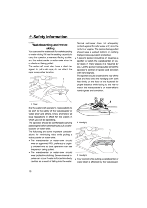 22
22 23
23 24
24 25
25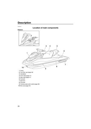 26
26 27
27 28
28 29
29 30
30 31
31 32
32 33
33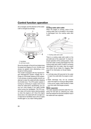 34
34 35
35 36
36 37
37 38
38 39
39 40
40 41
41 42
42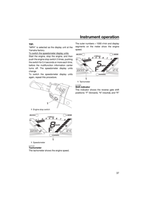 43
43 44
44 45
45 46
46 47
47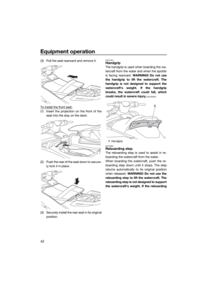 48
48 49
49 50
50 51
51 52
52 53
53 54
54 55
55 56
56 57
57 58
58 59
59 60
60 61
61 62
62 63
63 64
64 65
65 66
66 67
67 68
68 69
69 70
70 71
71 72
72 73
73 74
74 75
75 76
76 77
77 78
78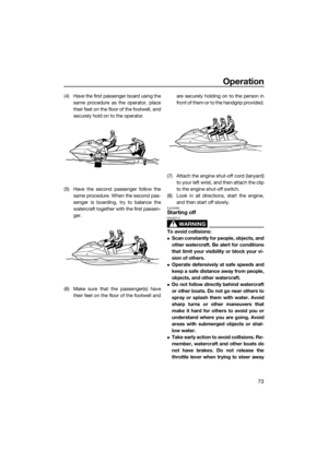 79
79 80
80 81
81 82
82 83
83 84
84 85
85 86
86 87
87 88
88 89
89 90
90 91
91 92
92 93
93 94
94 95
95 96
96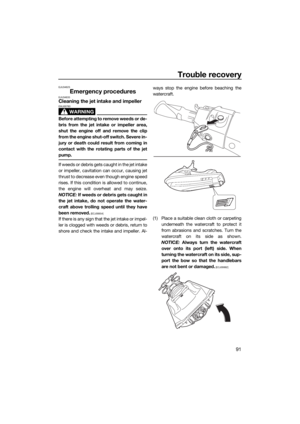 97
97 98
98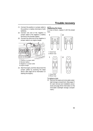 99
99 100
100 101
101 102
102 103
103 104
104 105
105
3Handlebar
4Front seat (page 41)
5Rear seat (page 41)
6Footwell
7Sponson
8Gunwale
9Cool")

3Handgrip (page 42)
4Stern eye (page 43)
5Stern drain plug (page 52)
6Reverse gate (page 30)
7Jet thrust nozzle
8Ride plate
9Rebo")

2Start switch (page 26)
3Electric trim up switch (page 32)
4Engine shut-off switch (page 26)
5Clip (page 26)
6Engine shut-off cord (la")

4Removable watertight storage compart-
ment (page 46)
5Air filter case
6Wa")