Page 41 of 110

Instrument and control functions
4-20
1
2
345
6
7
8
9
10
11
12
EAU13222
FuelMake sure there is sufficient gasoline in
the tank.
WARNING
EWA10882
Gasoline and gasoline vapors are
extremely flammable. To avoid fires
and explosions and to reduce the
risk of injury when refueling, followthese instructions. 1. Before refueling, turn off the en- gine and be sure that no one is sit-
ting on the vehicle. Never refuel
while smoking, or while in the vi-
cinity of sparks, open flames, or
other sources of ignition such as
the pilot lights of water heaters and
clothes dryers.
2. Do not overfill the fuel tank. When refueling, be sure to insert the
pump nozzle into the fuel tank filler
hole. Stop filling when the fuel
reaches the bottom of the filler
tube. Because fuel expands when
it heats up, heat from the engine or
the sun can cause fuel to spill out
of the fuel tank. 3. Wipe up any spilled fuel immedi-
ately. NOTICE: Immediately wipe
off spilled fuel with a clean, dry,
soft cloth, since fuel may deteri-
orate painted surfaces or plastic
parts.
[ECA10072]
4. Be sure to securely close the fuel tank cap.
WARNING
EWA15152
Gasoline is poisonous and can
cause injury or death. Handle gaso-
line with care. Never siphon gaso-
line by mouth. If you should swallow
some gasoline or inhale a lot of gas-
oline vapor, or get some gasoline in your eyes, see your doctor immedi-
ately. If gasoline spills on your skin,
wash with soap and water. If gaso-
line spills on your clothing, change
your clothes.
EAU75300
NOTICE
ECA11401
Use only unleaded gasoline. The use
of leaded gasoline will cause severe
damage to internal engine parts,
such as the valves and piston rings,as well as to the exhaust system.
1. Fuel tank filler tube
2. Maximum fuel level
2
1
Recommended fuel:
Premium unleaded gasoline (Gaso-
hol [E10] acceptable)
Fuel tank capacity: 17 L (4.5 US gal, 3.7 Imp.gal)
Fuel reserve amount:
4.0 L (1.06 US gal, 0.88 Imp.gal)
B67-9-E1_1.book 20 ページ 2017年1月23日 月曜日 午後6時21分
Page 42 of 110
.
Check that gasoline")
Instrument and control functions
4-21
1
2
34
5
6
7
8
9
10
11
12
TIP
This mark identifies the recom-
mended fuel for this vehicle as
specified by European regulation
(EN228).
Check that gasoline nozzle has thesame identifier when fueling.
Your Yamaha engine has been de-
signed to use premium unleaded gaso-
line with a research octane number of
95 or higher. If knocking (or pinging) oc-
curs, use a gasoline of a different
brand. Use of unleaded fuel will extend
spark plug life and reduce maintenance
costs.
Gasohol
There are two types of gasohol: gaso- hol containing ethanol and that contain-
ing methanol. Gasohol containing
ethanol can be used if the ethanol con-
tent does not exceed 10% (E10). Gas-
ohol containing methanol is not
recommended by Yamaha because it
can cause damage to the fuel system
or vehicle performance problems.
EAU74230
Fuel tank overflow hoseTIPSee page 7-10 for breather information.
Before operating the motorcycle:
Check the fuel tank overflow hose
connection.
Check the fuel tank overflow hose
for cracks or damage, and replace
it if necessary.
Make sure that the end of the fuel
tank overflow hose is not blocked,
and clean it if necessary.
Make sure that the fuel tank over-
flow hose is routed through the
clamp.
E10
1. Clamp
2. Fuel tank overflow hose
1
2
B67-9-E1_1.book 21 ページ 2017年1月23日 月曜日 午後6時21分
Page 43 of 110

Instrument and control functions
4-22
1
2
345
6
7
8
9
10
11
12
EAU13434
Catalytic converterThis model is equipped with a catalytic
converter in the exhaust system.
WARNING
EWA10863
The exhaust system is hot after op-
eration. To prevent a fire hazard or
burns:
Do not park the vehicle near
possible fire hazards such as
grass or other materials that
easily burn.
Park the vehicle in a place
where pedestrians or children
are not likely to touch the hot
exhaust system.
Make sure that the exhaust sys-
tem has cooled down before do-
ing any maintenance work.
Do not allow the engine to idle
more than a few minutes. Long
idling can cause a build-up ofheat.
NOTICE
ECA10702
Use only unleaded gasoline. The use
of leaded gasoline will cause unre- pairable damage to the catalytic
converter.
EAU57991
SeatTo remove the seat
1. Open the seat lock cover, insert the key into the seat lock, and then
turn the key counterclockwise.
2. While holding the key in that posi- tion, lift the rear of the seat up, and
then pull the seat off.
To install the seat 1. Insert the projections into the seat holders as shown.1. Seat lock
2. Seat lock cover
3. Unlock.
1 3
2
B67-9-E1_1.book 22 ページ 2017年1月23日 月曜日 午後6時21分
Page 44 of 110

Instrument and control functions
4-23
1
2
34
5
6
7
8
9
10
11
12 2. Push the rear of the seat down to
lock it in place.
3. Remove the key.
TIPMake sure that the seat is properly se-cured before riding.
EAU70410
Adjusting the front forkNOTICE
ECA22471
Use extra care to avoid scratch-
ing the gold-anodized finish
when making suspension ad-
justments.
To avoid damaging the suspen-
sion’s internal mechanisms, do
not attempt to turn beyond themaximum or minimum settings.
This model is equipped with adjustable
suspension. The spring preload, re-
bound damping force, and compres-
sion damping force of each leg can be
adjusted.WARNING
EWA10181
Always adjust both fork legs equal-
ly, otherwise poor handling and lossof stability may result.
Spring preload
To increase the spring preload and
thereby harden the suspension, turn
the adjusting nut on each fork in direc-
tion (a). To decrease the spring preload and thereby soften the suspension,
turn the adjusting nut on each fork in di-
rection (b).
Rebound damping force
To increase the rebound damping force
and thereby harden the rebound damp-
ing, turn the adjusting bolt on each fork
leg in direction (a). To decrease the re-
1. Projection
2. Seat holder
2
2 1
1. Spring preload adjusting nutSpring preload setting:
Minimum (soft):
0 turn(s) in direction (a)*
Standard: 9 turn(s) in direction (a)*
Maximum (hard): 15 turn(s) in direction (a)*
* With the adjusting nut fully turned in
direction (b)
1
(a) (b)
B67-9-E1_1.book 23 ページ 2017年1月23日 月曜日 午後6時21分
Page 45 of 110
.
Compression da")
Instrument and control functions
4-24
1
2
345
6
7
8
9
10
11
12
bound damping force and thereby soft-
en the rebound damping, turn the
adjusting bolt on each fork leg in direc-
tion (b).
Compression damping force
To increase the compression damping
force and thereby harden the compres-
sion damping, turn the adjusting bolt on each fork leg in direction (a). To de-
crease the compression damping force
and thereby soften the compression
damping, turn the adjusting bolt on
each fork leg in direction (b).
TIPAlthough the total number of clicks of a
damping force adjusting mechanism
may not exactly match the above spec-
ifications due to small differences in
production, the actual number of clicks
always represents the entire adjusting
range. To obtain a precise adjustment,
it would be advisable to check the num-
ber of clicks of each damping force ad-
justing mechanism and to modify the
specifications as necessary.
1. Rebound damping force adjusting boltRebound damping setting:
Minimum (soft):
14 click(s) in direction (b)*
Standard: 6 click(s) in direction (b)*
Maximum (hard): 1 click(s) in direction (b)*
* With the adjusting bolt fully turned in
direction (a)
1
(a) (b)
1. Compression damping force adjusting boltCompression damping setting:
Minimum (soft):
23 click(s) in direction (b)*
Standard: 17 click(s) in direction (b)*
Maximum (hard): 1 click(s) in direction (b)*
* With the adjusting bolt fully turned in
direction (a)
1
(a) (b)
B67-9-E1_1.book 24 ページ 2017年1月23日 月曜日 午後6時21分
Page 46 of 110

Instrument and control functions
4-25
1
2
34
5
6
7
8
9
10
11
12
EAU74240
Adjusting th e shock absorber
assembly
WARNING
EWA10222
This shock absorber assembly con-
tains highly pressurized nitrogen
gas. Read and understand the fol-
lowing information before handling
the shock absorber assembly.
Do not tamper with or attempt to
open the cylinder assembly.
Do not subject the shock ab-
sorber assembly to an open
flame or other high heat source.
This may cause the unit to ex-
plode due to excessive gas
pressure.
Do not deform or damage the
cylinder in any way. Cylinder
damage will result in poor
damping performance.
Do not dispose of a damaged or
worn-out shock absorber as-
sembly yourself. Take the shock
absorber assembly to a Yamahadealer for any service.
NOTICE
ECA10102
To avoid damaging the mechanism,
do not attempt to turn beyond themaximum or minimum settings.
This model is equipped with adjustable
suspension. The spring preload, re-
bound damping force, fast compres-
sion damping force, and slow
compression damping force can be ad-
justed.
Spring preload
1. Loosen the locknut.
2. To increase the spring preload and thereby harden the suspension,
turn the adjusting ring in direction
(a). To decrease the spring pre-
load and thereby soften the sus-
pension, turn the adjusting ring in
direction (b).
The spring preload setting is deter-
mined by measuring distance A.
The longer distance A is, the high-
er the spring preload; the shorter
distance A is, the lower the spring
preload.
Use the special wrench includ- ed in the additional tool kit to
make the adjustment.
1. Spring preload adjusting ring
2. Locknut
3. Special wrench
1. Distance A
(a)
(b)1
2
3
1
B67-9-E1_1.book 25 ページ 2017年1月23日 月曜日 午後6時21分
Page 47 of 110

Instrument and control functions
4-26
1
2
345
6
7
8
9
10
11
12
3. Tighten the locknut to the specified
torque. NOTICE: Always tighten
the locknut against the adjust-
ing ring, and then tighten the
locknut to the specified
torque.
[ECA22760]
Rebound damping force
To increase the rebound damping force
and thereby harden the rebound damp-
ing, turn the adjusting screw in direction
(a). To decrease the rebound damping
force and thereby soften the rebound
damping, turn the adjusting screw in di-
rection (b). Compression damping force
Fast compression damping force
To increase the compression damping
force and thereby harden the fast com-
pression damping, turn the adjusting
bolt in direction (a). To decrease the
compression damping force and there-by soften the compression damping,
turn the adjusting bolt in direction (b).
Slow compression damping force
To increase the compression damping
force and thereby harden the slow
compression damping, turn the adjust-
ing screw in direction (a). To decrease
Spring preload:
Minimum (soft): Distance A = 77.5 mm (3.05 in)
Standard:
Distance A = 81.5 mm (3.21 in)
Maximum (hard): Distance A = 85.5 mm (3.37 in)
Tightening torque: Locknut: 25 N·m (2.5 kgf·m, 18 lb·ft)
1. Rebound damping force adjusting screwRebound damping setting:Minimum (soft):
23 click(s) in direction (b)*
Standard: 11 click(s) in direction (b)*
Maximum (hard): 1 click(s) in direction (b)*
* With the adjusting screw fully turned
in direction (a)(a) (b)
1
1. Fast compression damping force
adjusting boltFast compression damping settingMinimum (soft):
5.5 turn(s) in direction (b)*
Standard: 3 turn(s) in direction (b)*
Maximum (hard): 0 turn(s) in direction (b)*
* With the adjusting bolt fully turned in
direction (a)
(a) (b)
1
B67-9-E1_1.book 26 ページ 2017年1月23日 月曜日 午後6時21分
Page 48 of 110
Instrument and control functions
4-27
1
2
34
5
6
7
8
9
10
11
12 the compression damping force and
thereby soften the compression damp-
ing, turn the adjusting screw in direction
(b).
TIPTo obtain a precise adjustment, it is ad-
visable to check the actual total number
of clicks or turns of each damping force adjusting mechanism. This adjustment
range may not exactly match the spec-
ifications listed due to small differences
in production.
EAU15152
Luggage strap holdersThere is a luggage strap holder on each
passenger footrest.
1. Slow compression damping force
adjusting screwSlow compression damping settingMinimum (soft):
18 click(s) in direction (b)*
Standard: 12 click(s) in direction (b)*
Maximum (hard): 1 click(s) in direction (b)*
* With the adjusting screw fully turned
in direction (a)
(a) (b)
1
1. Luggage strap holder
1
B67-9-E1_1.book 27 ページ 2017年1月23日 月曜日 午後6時21分
 1
1 2
2 3
3 4
4 5
5 6
6 7
7 8
8 9
9 10
10 11
11 12
12 13
13 14
14 15
15 16
16 17
17 18
18 19
19 20
20 21
21 22
22 23
23 24
24 25
25 26
26 27
27 28
28 29
29 30
30 31
31 32
32 33
33 34
34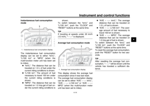 35
35 36
36 37
37 38
38 39
39 40
40 41
41 42
42 43
43 44
44 45
45 46
46 47
47 48
48 49
49 50
50 51
51 52
52 53
53 54
54 55
55 56
56 57
57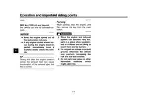 58
58 59
59 60
60 61
61 62
62 63
63 64
64 65
65 66
66 67
67 68
68 69
69 70
70 71
71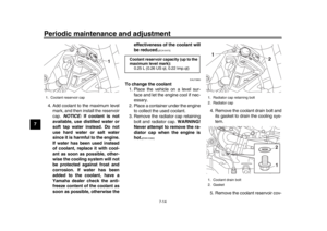 72
72 73
73 74
74 75
75 76
76 77
77 78
78 79
79 80
80 81
81 82
82 83
83 84
84 85
85 86
86 87
87 88
88 89
89 90
90 91
91 92
92 93
93 94
94 95
95 96
96 97
97 98
98 99
99 100
100 101
101 102
102 103
103 104
104 105
105 106
106 107
107 108
108 109
109.
TIPTo obtain a pr")