Page 25 of 110

Instrument and control functions
4-4
1
2
345
6
7
8
9
10
11
12
Right
EAU73921
Dimmer/Pass switch “ / /PASS”
Set this switch to “ ” for the high
beam and to “ ” for the low beam.
To flash the high beam, push the pass
side “PASS” of the switch while the
headlights are on low beam.
EAU66040
Turn signal switch “ / ”
To signal a right-hand turn, push this
switch to “ ”. To signal a left-hand
turn, push this switch to “ ”. When re-
leased, the switch returns to the center
position. To cancel the turn signal lights, push the switch in after it has re-
turned to the center position.
EAU66030
Horn switch “ ”
Press this switch to sound the horn.
EAU73961
Traction control system switch
“TCS”
See page 3-4 for an explanation of the
traction control system.
EAU66060
Stop/Run/Start switch “ / / ”
To crank the engine with the starter, set
this switch to “ ”, and then push the
switch down towards “ ”. See page
6-1 for starting instructions prior to
starting the engine.
Set this switch to “ ” to stop the engine
in case of an emergency, such as when
the vehicle overturns or when the throt-
tle cable is stuck.
EAU66010
Hazard switch “ ”
With the key in the “ON” or “ ” posi-
tion, use this switch to turn on the haz-
ard lights (simultaneous flashing of all
turn signal lights).
The hazard lights are used in case of
an emergency or to warn other drivers
when your vehicle is stopped where it
might be a traffic hazard.
NOTICE
ECA10062
Do not use the hazard lights for an
extended length of time with the en-
gine not running, otherwise the bat-tery may discharge.
EAU73951
Cruise control switches
See page 3-1 for an explanation of the
cruise control system.
EAU73941
“SELECT” switch
This switch is used to perform selec-
tions in the odometer, tripmeters, cool-
ant temperature and ambient
temperature display of the multi-func-
tion meter unit.
See “Multi-function meter unit” on page
4-8 for detailed information.
1. Stop/Run/Start switch “ / / ”
2. Mode switch “MODE”
3. Hazard switch “ ”
STOPM
ODERUNSTA R T
3
2
1
B67-9-E1_1.book 4 ページ 2017年1月23日 月曜日 午後6時21分
Page 26 of 110

Instrument and control functions
4-5
1
2
34
5
6
7
8
9
10
11
12
EAU73931
Drive mode switch “MODE”
See page 3-3 for an explanation of the
drive mode.
EAU4939C
Indicator lights and warning
lights
EAU11032
Turn signal indicator lights “ ” and
“”
Each indicator light will flash when its
corresponding turn signal lights are
flashing.
EAU11061
Neutral indicator light “ ”
This indicator light comes on when the
transmission is in the neutral position.
EAU11081
High beam indicator light “ ”
This indicator light comes on when the
high beam of the headlight is switched
on.
EAU59962
Oil pressure warning light “ ”
This warning light comes on if the en-
gine oil pressure is low.
The electrical circui t of the warning light
can be checked by turning the key to
“ON”. The warning light should come
on again after going off briefly, and then
remain on until the engine is started.
If the warning light does not come on
initially when the key is turned to “ON”,
have a Yamaha dealer check the elec-
1. Engine trouble warning light “ ”
2. Coolant temperature warning light “ ”
3. Neutral indicator light “ ”
4. High beam indicator light “ ”
5. Left turn signal indicator light “ ”
6. Steering damper warning light “ ”
7. Oil pressure warning light “ ”
8. Immobilizer system indicator light “ ”
9. Traction control system indicator light “”
10.Cruise control setting indicator light “SET”
11.Shift timing indicator light
12.Right turn signal indicator light “ ”
13.Cruise control system indicator light “ ”
14.Anti-lock Brake System (ABS) warning light “ ”
567 9 810
11
12
13
14
4
3
2
1
ABS
B67-9-E1_1.book 5 ページ 2017年1月23日 月曜日 午後6時21分
Page 27 of 110

Instrument and control functions
4-6
1
2
345
6
7
8
9
10
11
12
trical circuit.
NOTICE
ECA21210
If the warning light comes on when
the engine is running, stop the en-
gine immediately and check oil level.
If the oil level is below the minimum
level, add sufficient oil of the recom-
mended type to raise it up to the cor-
rect level. If the oil pressure warning
light remains on even if the oil level
is correct, immediately turn the en-
gine off and have a Yamaha dealercheck the vehicle.TIPIf the warning light does not go off after
starting the engine, check the engine oil
level and add oil if necessary. (See
page 7-10.)
If the warning light remains on after
adding engine oil, have a Yamahadealer check the vehicle.
EAU74072
Cruise control indicator lights
“”/“SET”
These indicator lights come on when the cruise control system is activated.
(See page 3-1.)
TIPWhen the vehicle is turned on, these
lights should come on for a few sec-
onds and then go off. If the lights do not
come on, have a Yamaha dealer checkvehicle.
EAU11447
Coolant temperature warning light
“”
This warning light comes on if the en-
gine overheats. If this occurs, stop the
engine immediately and allow the en-
gine to cool.
The electrical circuit of the warning light
can be checked by turning the key to
“ON”. The warning light should come
on for a few seconds, and then go off.
If the warning light does not come on
initially when the key is turned to “ON”,
or if the warning light remains on, have
a Yamaha dealer check the electrical
circuit.NOTICE
ECA10022
Do not continue to operate the en-
gine if it is overheating.TIP
For radiator-fan-equipped vehi-
cles, the radiator fan(s) automati-
cally switch on or off according to
the coolant temperature in the ra-
diator.
If the engine overheats, see page7-38 for further instructions.
EAU73171
Engine trouble warning light “ ”
This warning light comes on if a prob-
lem is detected in the engine or other
vehicle control system. If this occurs,
have a Yamaha dealer check the
on-board diagnostic system.
The electrical circuit of the warning light
can be checked by turning the key to
“ON”. The warning light should come
on for a few seconds, and then go off.
If the warning light does not come on
initially when the key is turned to “ON”,
or if the warning light remains on, have
a Yamaha dealer check the vehicle.
B67-9-E1_1.book 6 ページ 2017年1月23日 月曜日 午後6時21分
Page 28 of 110

Instrument and control functions
4-7
1
2
34
5
6
7
8
9
10
11
12
EAU69891
ABS warning light “ ”
In normal operation, this warning light
comes on when the key is turned to
“ON”, and goes off after traveling at a
speed of 10 km/h (6 mi/h) or higher.
If the ABS warning light:
does not come on when the key is
turned to “ON”
comes on or flashes while riding
does not go off after traveling at a
speed of 10 km/h (6 mi/h) or higher
The ABS may not work correctly. If any
of the above occurs, have a Yamaha
dealer check the system as soon as
possible. (See page 4-18 for an expla-
nation of the ABS.)WARNING
EWA16041
If the ABS warning light does not go
off after traveling at a speed of 10
km/h (6 mi/h) or higher, or if the
warning light comes on or flashes
while riding, the brake system re-
verts to conventional braking. If ei-
ther of the above occurs, or if the
warning light does not come on at
all, use extra caution to avoid possi-
ble wheel lock during emergency braking. Have a Yamaha dealer
check the brake system and electri-
cal circuits as soon as possible.
EAU74081
Traction control system indicator
light “ ”
This indicator light will flash when trac-
tion control has engaged.
If the traction control system is turned
off, this indicator light will come on.TIPWhen the vehicle is turned on, the light
should come on for a few seconds and
then go off. If the light does not come
on, or if the light remains on, have aYamaha dealer check vehicle.
EAU74100
Steering damper warning light “ ”
This warning light comes on if a prob-
lem is detected in the steering damper.
If this occurs, have a Yamaha dealer
check the vehicle.
The electrical circuit of the warning light
can be checked by turning the key to
“ON”. The warning light should come
on for a few seconds, and then go off.If the warning light does not come on
initially when the key is turned to “ON”,
or if the warning light remains on, have
a Yamaha dealer check the electrical
circuit.
EAU74090
Shift timing indicator light
This indicator light can be set to come
on and go off at the desired engine
speeds and is used to inform the rider
when it is time to shift to the next higher
gear. (See page 4-15.)
The electrical circui
t of the indicator
light can be checked by turning the key
to ON. The indicator light should come
on for a few seconds, and then go off.
If the indicator light does not come on
initially when the key is turned to ON, or
if the indicator light remains on, have a
Yamaha dealer check the electrical cir-
cuit.
EAU73120
Immobilizer system indicator light
“”
When the key is turned to “OFF” and 30
seconds have passed, the indicator
light will flash steadily to indicate the im-
ABS
B67-9-E1_1.book 7 ページ 2017年1月23日 月曜日 午後6時21分
Page 29 of 110

Instrument and control functions
4-8
1
2
345
6
7
8
9
10
11
12
mobilizer system is enabled. After 24
hours have passed, the indicator light
will stop flashing, however the immobi-
lizer system is still enabled.
The electrical circuit of the indicator
light can be checked by turning the key
to “ON”. The indicator light should
come on for a few seconds, and then
go off.
If the indicator light does not come on
initially when the key is turned to “ON”,
if the indicator light remains on, or if the
indicator light flashes in a pattern (if a
problem is detected in the immobilizer
system, the immobili
zer system indica-
tor light will flash in a pattern), have a
Yamaha dealer check the vehicle.
TIPIf the immobilizer system indicator light
flashes in the pattern, slowly 5 times
then quickly 2 times, this could be
caused by transponder interference. Ifthis occurs, try the following.
1. Make sure there are no other im- mobilizer keys close to the main
switch. Other immobilizer system
keys may cause signal interfer-
ence and prevent the engine from starting.
2. Use the code re-registering key to start the engine.
3. If the engine starts, turn it off, and try starting the engine with the
standard keys.
4. If one or both of the standard keys do not start the engine, take the
vehicle and all 3 keys to a Yamaha
dealer to have the standard keys
re-registered.
EAU79182
Multi-function meter unit1. “CLOCK” button
2. “RESET” button
12
B67-9-E1_1.book 8 ページ 2017年1月23日 月曜日 午後6時21分
Page 30 of 110

Instrument and control functions
4-9
1
2
34
5
6
7
8
9
10
11
12
WARNING
EWA12423
Be sure to stop the vehicle before
making any setting changes to the
multi-function meter unit. Changing
settings while riding can distract the
operator and increase the risk of an
accident.
The multi-function meter unit is
equipped with the following:
a speedometer
a tachometer
a clock
a fuel meter
a coolant/air temperature display
an eco indicator
a transmission gear display
a drive mode display
a TCS display
a QS indicator
a multi-function display
TIPTo switch the multi-function meter unit
between kilometers and miles, push
the “CLOCK” button and “RESET” but-ton at the same time. Speedometer
The speedometer shows the vehicle’s
traveling speed.
Tachometer
1. Transmission gear display
2. Clock
3. Tachometer
4. Coolant temperature display/air
temperature display
5. Speedometer
6. Fuel meter
7. Eco indicator “ECO”
8. Drive mode display
9. TCS display
10.QS indicator
11.Multi-function display12 3 5 46
9
10 7 8
11
1. Speedometer
1. Tachometer
2. Tachometer red zone
1
12
B67-9-E1_1.book 9 ページ 2017年1月23日 月曜日 午後6時21分
Page 31 of 110

Instrument and control functions
4-10
1
2
345
6
7
8
9
10
11
12
The tachometer allows the rider to
monitor the engine speed and keep it
within the ideal power range.
When the key is turned to “ON”, the ta-
chometer will sweep across the r/min
range and then return to zero r/min in
order to test the electrical circuit.
NOTICE
ECA10032
Do not operate the engine in the ta-
chometer red zone.Red zone: 11800 r/min and above
Clock
The clock uses a 12-hour time system.
To set the clock
1. Turn the key to “ON”.
2. Push the “CLOCK” button for two
seconds.
3. When the hour digits start flashing, push the “RESET” button to set the
hours.
4. Push the “CLOCK” button, and the minute digits will start flashing.
5. Push the “RESET” button to set the minutes.
6. Push the “CLOCK” button and then release it to start the clock.
Fuel meter
The fuel meter indicates the amount of
fuel in the fuel tank. The display seg- ments of the fuel meter disappear from
“F” (full) towards “E” (empty) as the fuel
level decreases. When the last seg-
ment starts flashing, refuel as soon as
possible.
TIPIf a problem is detected in the electrical
circuit, the fuel level segments and “ ”
will flash repeatedly. If this occurs, havea Yamaha dealer check vehicle.
Coolant/air temperature display
Push the “SELECT” switch for two sec-
onds to switch the display between the
coolant temperature mode “
C” and air
temperature mode.
1. Clock
1
1. Fuel meter
1
1. Select switch “SELECT”
R ESSE T
PAS
S
TCS
SELECT
1
B67-9-E1_1.book 10 ページ 2017年1月23日 月曜日 午後6時21分
Page 32 of 110

Instrument and control functions
4-11
1
2
34
5
6
7
8
9
10
11
12 Coolant temperature
This mode shows the coolant tempera-
ture from 40
C to 124 C in 1 C incre-
ments.
If the message “Hi” flashes, stop the ve-
hicle, then stop the engine, and let the
engine cool. (See page 7-38.)TIP
When the coolant temperature is
below 40 C, “Lo” will be displayed.
The coolant temperature varies
with changes in the weather andengine load. Air temperature
This mode shows the air temperature
from –9
C to 50 C in 1 C increments.TIP
–9 C will be displayed even if the
air temperature falls below –9 C.
The temperature displayed may
vary from the actual ambient tem-perature. Eco indicator
This indicator comes on when the vehi-
cle is being operated in an environmen-
tally friendly, fuel-efficient manner. The
indicator goes off when the vehicle is
stopped.
TIPConsider the following tips to reduce
fuel consumption:
Avoid high engine speeds during
acceleration.
Travel at a constant speed.
Select the transmission gear that
is appropriate for the vehiclespeed.
1. Coolant temperature display
1
1. Air temperature display
1
1. Eco indicator “ECO”
1
B67-9-E1_1.book 11 ページ 2017年1月23日 月曜日 午後6時21分
 1
1 2
2 3
3 4
4 5
5 6
6 7
7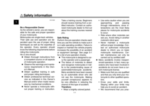 8
8 9
9 10
10 11
11 12
12 13
13 14
14 15
15 16
16 17
17 18
18 19
19 20
20 21
21 22
22 23
23 24
24 25
25 26
26 27
27 28
28 29
29 30
30 31
31 32
32 33
33 34
34 35
35 36
36 37
37 38
38 39
39 40
40 41
41 42
42 43
43 44
44 45
45 46
46 47
47 48
48 49
49 50
50 51
51 52
52 53
53 54
54 55
55 56
56 57
57 58
58 59
59 60
60 61
61 62
62 63
63 64
64 65
65 66
66 67
67 68
68 69
69 70
70 71
71 72
72 73
73 74
74 75
75 76
76 77
77 78
78 79
79 80
80 81
81 82
82 83
83 84
84 85
85 86
86 87
87 88
88 89
89 90
90 91
91 92
92 93
93 94
94 95
95 96
96 97
97 98
98 99
99 100
100 101
101 102
102 103
103 104
104 105
105 106
106 107
107 108
108 109
109