Page 6 of 140
EBU17331
IMPORTANT MANUAL INFORMATION
EBU17343FAILURE TO FOLLOW THE WARNINGS CONTAINED IN THIS MANUAL CAN RESULT IN SERIOUS IN-
JURY OR DEATH.
Particularly important information is distinguished in this manual by the following notations:
* Product and specifications are subject to change without notice. This is the safety alert symbol. It is used to alert you to potential per-
sonal injury hazards. Obey all safety messages that follow this sym-
bol to avoid possible injury or death.
A WARNING indicates a hazardous situation which, if not avoided,
could result in death or serious injury.
A NOTICE indicates special precautions that must be taken to avoid
damage to the vehicle or other property.
A TIP provides key information to make procedures easier or clearer.
WARNING
NOTICETIPUB1463E0.book Page 1 Thursday, August 4, 2016 2:12 PM
Page 28 of 140
4-1
4
EBU17738
INSTRUMENT AND CONTROL FUNCTIONS
EBU17771Main switchThe positions of the main switch are as follows:
ON
All electrical systems are supplied with power. The
headlights, meter lighting and taillight come on
when the light switch is on, and the engine can be
started. The key cannot be removed.
OFF
All electrical systems are off. The key can be re-
moved.
1. Main switch
UB1463E0.book Page 1 Thursday, August 4, 2016 2:12 PM
Page 29 of 140

4-2
4
EBU17817Indicator lights and warning lightEBU17871Neutral indicator light “NEUTRAL”
This indicator light comes on when the transmis-
sion is in the neutral position.EBU17851Reverse indicator light “REVERSE”
This indicator light comes on when the transmis-
sion is in the reverse position.
EBU26933Oil temperature warning light “ ”
This warning light comes on when the engine
overheats. When this occurs, stop the engine as
soon as it is safe to do so, and allow it to cool.
The electrical circuit of the warning light can be
checked by turning the key to “ON”, with the en-
gine stop switch set to “ ”, and then pushing the
start switch.
If the warning light does not come on while the
start switch is being pushed, or if the warning light
remains on after the start switch is released, have
a Yamaha dealer check the electrical circuit.
If the warning light stays on when the engine is
cool, have a Yamaha dealer check the electrical
circuit.NOTICEECB00011The engine may overheat if the ATV is over-
loaded. In this case, reduce the load to spec-
ification.
Start the engine after making sure that the
warning light is out. Continuous use while
the warning light is on may cause damage to
the engine.
1. Reverse indicator light “REVERSE”
2. Neutral indicator light “NEUTRAL”
3. Oil temperature warning light “ ”UB1463E0.book Page 2 Thursday, August 4, 2016 2:12 PM
Page 50 of 140

6-1
6
EBU19882
OPERATION
EBU19902Read the Owner’s Manual carefully before riding
the ATV. If there is a control or function you do not
understand, ask your Yamaha dealer.
WARNING
EWB00632Read the Owner’s Manual carefully to become
familiar with all controls in order to help pre-
vent any loss of control, which could cause an
accident or injury. EBU26954Starting a cold engineNOTICEECB00151See the “Engine break-in” section on page 6-4
prior to operating the engine for the first time. 1. Set the parking brake.
2. Turn the fuel cock to “ON”.
3. Turn the key to “ON” and the engine stopswitch to “ ”. 4. Shift the drive select lever into the neutral po-
sition. The neutral indicator light should come
on. If the indicator light does not come on,
have a Yamaha dealer check the electrical
circuit.
TIPThe engine can be started under the following
conditions:
The drive select lever is in the neutral position.
The rear brake lever is applied with the drive se-
lect lever in any position. However, it is recom-
mended to shift into the neutral position before
starting the engine. 5. Use the starter (choke) in reference to the fi-
gure:
Position (1):
Cold engine start with ambient temperature
below 5 °C (40 °F).
Position (2):
Cold engine start with ambient temperature
between 0 °C (30 °F) and 30 °C (90 °F).
UB1463E0.book Page 1 Thursday, August 4, 2016 2:12 PM
Page 120 of 140

8-41
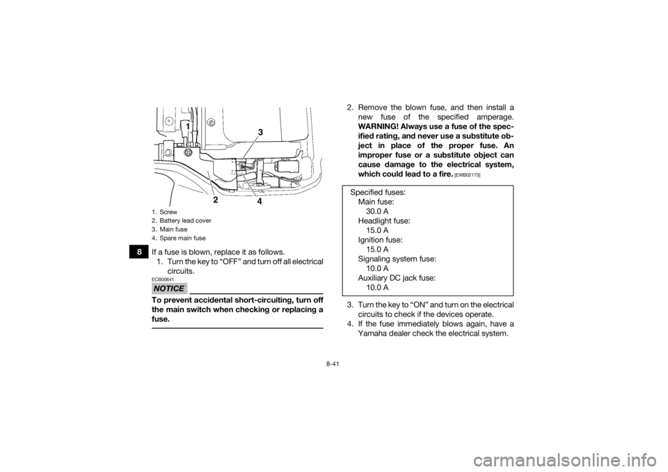
8If a fuse is blown, replace it as follows.
1. Turn the key to “OFF” and turn off all electrical circuits.
NOTICEECB00641To prevent accidental short-circuiting, turn off
the main switch when checking or replacing a
fuse.
2. Remove the blown fuse, and then install anew fuse of the specified amperage.
WARNING! Always use a fuse of the spec-
ified rating, and never use a substitute ob-
ject in place of the proper fuse. An
improper fuse or a substitute object can
cause damage to the electrical system,
which could lead to a fire.
[EWB02173]
3. Turn the key to “ON” and turn on the electricalcircuits to check if the devices operate.
4. If the fuse immediately blows again, have a Yamaha dealer check the electrical system.
1. Screw
2. Battery lead cover
3. Main fuse
4. Spare main fuse
43
2
1
Specified fuses:Main fuse:30.0 A
Headlight fuse: 15.0 A
Ignition fuse: 15.0 A
Signaling system fuse: 10.0 A
Auxiliary DC jack fuse: 10.0 A
UB1463E0.book Page 41 Thursday, August 4, 2016 2:12 PM