Page 561 of 716

5618-1. Essential information
8
When trouble arises
HIGHLANDER_HV_U (OM48F12U)
Steadily step on the brake pedal with both feet and firmly depress it.
Do not pump the brake pedal repeatedly as this will increase the effort
required to slow the vehicle.
Shift the shift lever to N.
If the shift lever is shifted to N
After slowing down, stop the vehicle in a safe place by the road.
Stop the hybrid system.
If the shift lever cannot be shifted to N
Keep depressing the brake pedal with both feet to reduce vehicle
speed as much as possible.
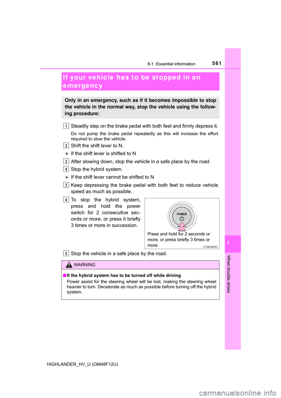
To stop the hybrid system,
press and hold the power
switch for 2 consecutive sec-
onds or more, or press it briefly
3 times or more in succession.
Stop the vehicle in a safe place by the road.
If your vehicle has to be stopped in an
emergency
Only in an emergency, such as if it becomes impossible to stop
the vehicle in the normal way, st op the vehicle using the follow-
ing procedure:
1
2
3
4
3
Press and hold for 2 seconds or
more, or press briefly 3 times or
more
4
WARNING
■ If the hybrid system has to be turned off while driving
Power assist for the steering wheel will be lost, making the steering wheel
heavier to turn. Decelerate as much as possible before turning off the hybrid
system.
5
Page 572 of 716

5728-2. Steps to take in an emergency
HIGHLANDER_HV_U (OM48F12U)
■SRS warning light
This warning light system monitors the airbag sensor assembly, front impact
sensors, side impact sensors (front door), side impact sensors (rear), driver’s
seat position sensor, driver’s seat belt buckle switch, front passenger occu-
pant classification system (ECU and sens ors), “AIR BAG ON” indicator light,
“AIR BAG OFF” indicator light, front passenger’s seat belt buckle switch,
driver’s seat belt pretensioner, front passenger’s seat belt pretensioner and
force limiter, airbags, interconnecting wiring and power sources.
( →P. 43)
■ Front passenger detection sensor, seat belt reminder and warning
buzzer
If luggage is placed on the front passenger seat, the front passenger detec-
tion sensor may cause the warning light to flash and the warning buzzer to
sound even if a passenger is not sitting in the seat.
■ If the malfunction indicator la mp comes on while driving
First check the following:
● Is the fuel tank empty?
If it is, fill the fuel tank immediately.
● Is the fuel tank cap loose?
If it is, tighten it securely.
The light will go off after several driving trips.
If the light does not go off even after several trips, contact your Toyota dealer
as soon as possible.
■ Electric power steering system warning light (warning buzzer)
When the 12-volt battery charge beco mes insufficient or the voltage tem-
porarily drops, the electric power steering system warning light may come
on and the warning buzzer may sound.
■When the tire pressure warning light comes on
Check the tire inflation pressure and adjust to the appropriate level. Push-
ing the tire pressure warning reset switch will not turn off the tire pressure
warning light.
■The tire pressure warning light may come on due to natural causes
The tire pressure warning light may come on due to natural causes such
as natural air leaks and tire inflat ion pressure changes caused by tem-
perature. In this case, adjusting the ti re inflation pressure will turn off the
warning light (afte r a few minutes).
Page 594 of 716

5948-2. Steps to take in an emergency
HIGHLANDER_HV_U (OM48F12U)
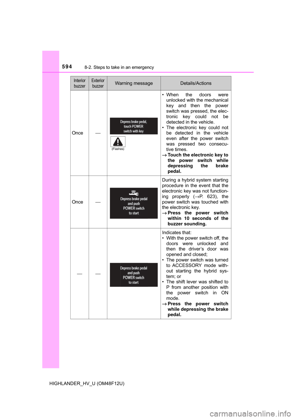
Once⎯
• When the doors wereunlocked with the mechanical
key and then the power
switch was pressed, the elec-
tronic key could not be
detected in the vehicle.
• The electronic key could not be detected in the vehicle
even after the power switch
was pressed two consecu-
tive times.
→ Touch the electronic key to
the power switch while
depressing the brake
pedal.
Once⎯
During a hybrid system starting
procedure in the event that the
electronic key was not function-
ing properly ( →P. 623), the
power switch was touched with
the electronic key.
→ Press the power switch
within 10 seconds of the
buzzer sounding.
⎯⎯
Indicates that:
• With the power switch off, the
doors were unlocked and
then the driver’s door was
opened and closed;
• The power switch was turned to ACCESSORY mode with-
out starting the hybrid sys-
tem; or
• The shift lever was shifted to P from another position with
the power switch in ON
mode.
→ Press the power switch
while depressing the brake
pedal.
Interior
buzzerExterior buzzerWarning messageDetails/Actions
(Flashes)
Page 600 of 716
6008-2. Steps to take in an emergency
HIGHLANDER_HV_U (OM48F12U)
Pull the strap upwards to open
the center deck board.
To secure the center deck
board, remove the hook on the
backside of the center deck
board and attach the hook to
the head restraint on the third
seats as shown.
Remove the jack cover.
Remove the jack after removing
the hook.
Taking out the jack
1
2
3
4
Page 601 of 716
6018-2. Steps to take in an emergency
8
When trouble arises
HIGHLANDER_HV_U (OM48F12U)
Pull the strap upwards to open
the center deck board.
To secure the center deck
board, remove the hook on the
backside of the center deck
board and attach the hook to
the head restraint on the third
seats as shown.
Remove the mat.
Remove the cover.
If it is difficult to remove the
cover, you can use your key.
Taking out the spare tire
1
2
3
4
Page 619 of 716

6198-2. Steps to take in an emergency
8
When trouble arises
HIGHLANDER_HV_U (OM48F12U)
WARNING
■Replacing a flat tire for vehicles with power back door
In cases such as when replacing tires, make sure to turn off the power
back door main switch ( →P. 133). Failure to do so may cause the back
door to operate unintentionally if the power back door switch is acciden-
tally touched, resulting in hands and fingers being caught and injured.
■After using the tools and jack
Before driving, make sure all the tools and jack are securely in place in
their storage location to reduce the po ssibility of personal injury during a
collision or sudden braking.
NOTICE
■Be careful when driving over bumps with the compact spare tire
installed on the vehicle.
The vehicle becomes lower when driving with the compact spare tire
compared to when driving with standa rd tires. Be careful when driving
over uneven road surfaces.
■Driving with tire chains and the compact spare tire
Do not fit tire chains to the compact spare tire.
Tire chains may damage the vehicle body and adversely affect driving
performance.
■When replacing the tires
When removing or fitting the wheels, tires or the tire pressure warning
valve and transmitter, contact your Toyota dealer as the tire pressure
warning valve and transmitter may be damaged if not handled correctly.
■To avoid damage to the tire pressure warning valves and transmit-
ters
When a tire is repaired with liquid sealants, the tire pressure warning
valve and transmitter may not operate properly. If a liquid sealant is
used, contact your Toyota dealer or other qualified service shop as soon
as possible. Make sure to replace the tire pressure warning valve and
transmitter when replacing the tire. ( →P. 524)
Page 620 of 716

6208-2. Steps to take in an emergency
HIGHLANDER_HV_U (OM48F12U)
NOTICE
■When stowing the flat tire
●Ensure that there is no object caught between the tire and the vehicle
underbody.
●Securely tighten the spare tire clam p bolt to hold the spare wheel car-
rier by the hook.
●Stow the flat tire in the spare tire location. Failure to do so may cause
damage to the spare tire carrier. Proper storage redu ces the possibility
of injury in a collision or during sudden braking.
●Have the flat tire repaired and the spare tire replaced with it as soon as
possible.
■Proper storage of the spare tire
●Do not attempt to turn the spare tire clamp bolt without a tire on the
hoist assembly, as doing so may cause the wire cable to slip off of the
shaft inside the unit and the wire cable may not be able to be raised or
lowered. If the spare tire clamp bolt has been turned without a tire on
the hoist assembly and the wire cable cannot be raised or lowered,
contact your Toyota dealer.
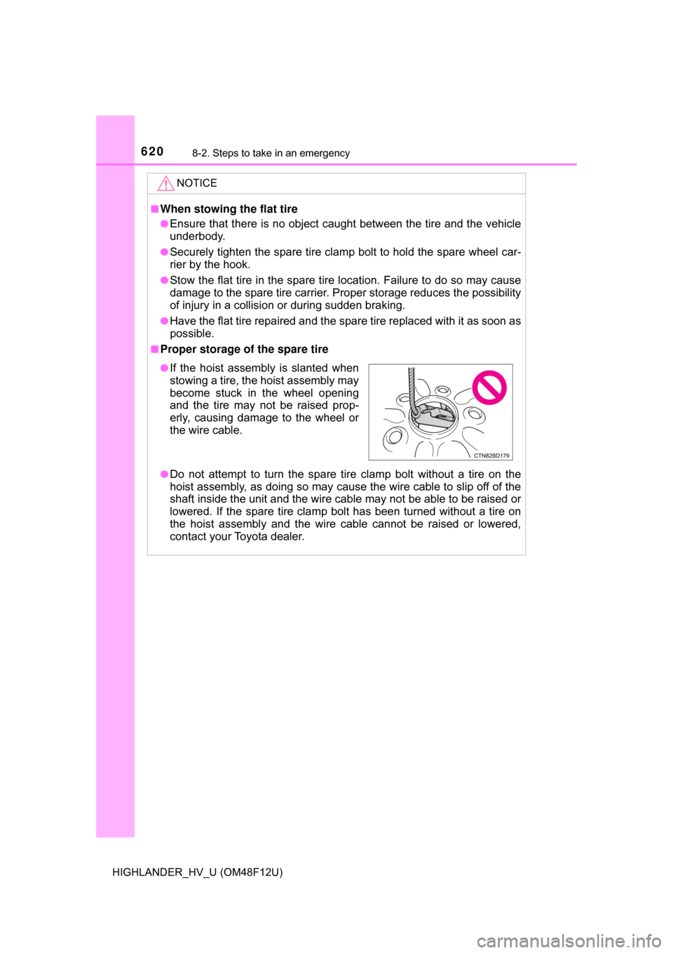
●If the hoist assembly is slanted when
stowing a tire, the hoist assembly may
become stuck in the wheel opening
and the tire may not be raised prop-
erly, causing damage to the wheel or
the wire cable.
Page 664 of 716

6649-1. Specifications
HIGHLANDER_HV_U (OM48F12U)
*: Table 1 ⎯ Occupant loading and distribution for vehicle normal load for
various designated seating capacities
Section width
The linear distance between the exteriors of
the sidewalls of an inflated tire, excluding ele-
vations due to labeling, decoration, or protec-
tive bands
SidewallThat portion of a tire between the tread and
bead
Sidewall separationThe parting of the rubber compound from the
cord material in the sidewall
Snow tire
A tire that attains a traction index equal to or
greater than 110, compared to the ASTM E-
1136 Standard Reference Test Tire, when
using the snow traction test as described in
ASTM F-1805-00, Standard Test Method for
Single Wheel Driving Traction in a Straight
Line on Snow-and Ice-Covered Surfaces, and
which is marked with an Alpine Symbol ( )
on at least one sidewall
Test rim
The rim on which a tire is fitted for testing, and
may be any rim listed as appropriate for use
with that tire
TreadThat portion of a tire that comes into contact
with the road
Tread ribA tread section running circumferentially
around a tire
Tread separationPulling away of the tread from the tire carcass
Treadwear indicators
(TWI)The projections within the principal grooves
designed to give a visual indication of the
degrees of wear of the tread
Wheel-holding fixtureThe fixture used to hold the wheel and tire
assembly securely during testing
Tire related termMeaning