2017 SUBARU LEGACY key
[x] Cancel search: keyPage 6 of 610

Warranties
&Warranties for U.S.A.
SUBARU vehicles distributed by Subaru
of America, Inc. and sold at retail by an
authorized SUBARU dealer in the United
States come with the following warranties:
. SUBARU Limited Warranties
. Federal Emission Control Systems
Warranties
. California Emissions Control Sys-
tems Warranties
All warranty information, including applic-
ability, details of coverage and exclusions,
is in the “Warranty and Maintenance
Booklet ”. Read these warranties carefully.
&Warranties for Canada
SUBARU vehicles distributed by Subaru
Canada, Inc. and sold at retail by an
authorized SUBARU dealer in Canada
come with the following warranties:
. SUBARU Limited Warranty
. Emission Control System Warranty
All warranty information, including applic-
ability, details of coverage and exclusions,
is in the “Warranty and Service Booklet ”.
Read these warranties carefully.
& Warranties except for U.S.A.
and Canada
All warranty information, including details
of coverage and exclusions, is in the
“Warranty and Maintenance Booklet ”.
Read these warranties carefully.
How to use this Owner ’s
Manual
& Using your Owner ’s Manual
Before you operate your vehicle, carefully
read this manual. To protect yourself and
extend the service life of your vehicle,
follow the instructions in this manual.
Failure to observe these instructions may
result in serious injury and damage to your
vehicle.
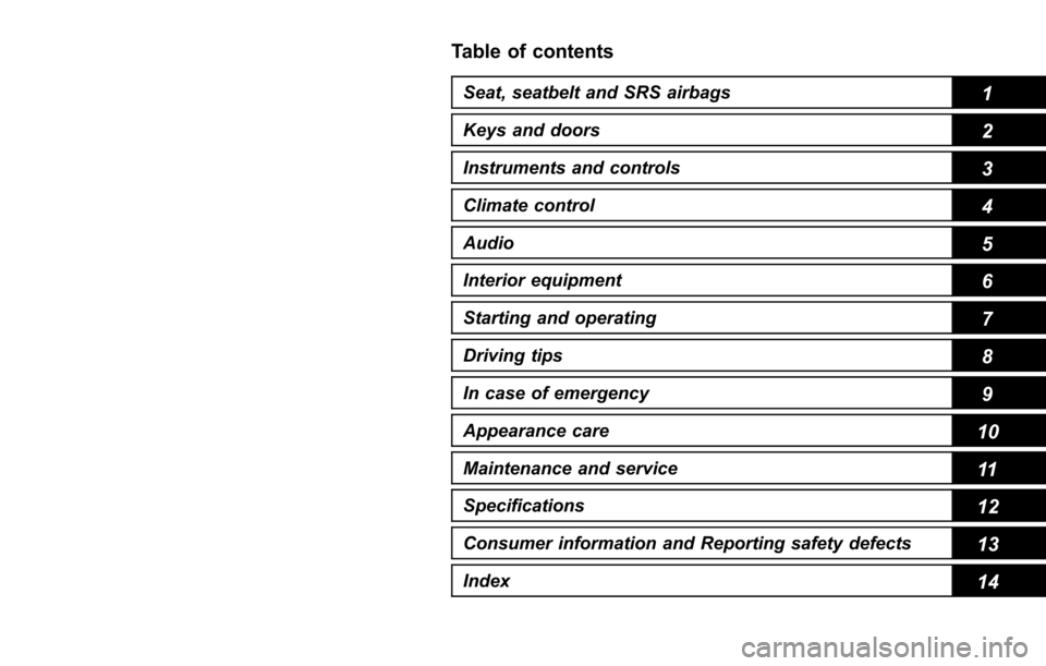
This manual is composed of fourteen
chapters. Each chapter begins with a brief
table of contents, so you can usually tell at
a glance if that chapter contains the
information you want.
Chapter 1: Seat, seatbelt and SRS
airbags
This chapter informs you how to use the
seat and seatbelt and contains precau-
tions for the SRS airbags.
Chapter 2: Keys and doors
This chapter informs you how to operate
the keys, locks and windows.
Chapter 3: Instruments and controls
This chapter informs you about the opera-
tion of instrument panel indicators and
how to use the instruments and other
switches.
– CONTINUED –
1
Page 13 of 610

in the front passenger’s seat. For further
information, consult you r veterinarian,
local animal protection society or pet
shop.
& Tire pressures
WARNING
Driving at high speeds with exces-
sively low tire pressures can cause
the tires to deform severely and to
rapidly become hot. A sharp in-
crease in temperature could cause
tread separation, and destruction of
the tires. The resulting loss of
vehicle control could lead to an
accident.
Check and, if necessary, adjust the
pressure of each tire (including the spare)
at least once a month and before any long
journey.
Check the tire pressure when the tires are
cold. Use a pressure gauge to adjust the
tire pressures to the values shown on the
tire placard. For detailed information, refer
to “Tires and wheels” F11-25.
& Attaching accessories
WARNING
. Do not attach any accessories,
labels or stickers (other than
properly placed inspection stick-
ers) to the windshield. Such
items may obstruct your view.
. If it is necessary to attach an
accessory (such as an electronic
toll collection (ETC) device or
security pass) to the windshield,
consult your SUBARU dealer for
details on the proper location.
General information
& California proposition 65
warning
WARNING
Engine exhaust, some of its consti-
tuents, and certain vehicle compo-
nents contain or emit chemicals
known to the State of California to
cause cancer and birth defects or
other reproductive harm. In addi-
tion, certain fluids in vehicles and
certain components of product wear
contain or emit chemicals known to
the State of California to cause
cancer and birth defects or other
reproductive harm.
&California Perchlorate Advi-
sory
Certain vehicle components such as air-
bag modules, seatbelt pretensioners and
keyless entry transmitter batteries may
contain perchlorate material. Special
handling may apply for service or vehicle
end of life disposal. See www.dtsc.ca.gov/
hazardouswaste/perchlorate.
8
Page 16 of 610

Table of contents
Seat, seatbelt and SRS airbags1
Keys and doors2
Instruments and controls
Climate control4
Audio5
Interior equipment6
Starting and operating7
Driving tips8
In case of emergency9
Appearance care10
Maintenance and service11
Specifications12
Consumer information and Reporting safety defects13
Index14
3
Page 30 of 610

&Warning and indicator lights
Mark Name Page
Seatbelt warning light 3-13
Front passenger’s
seatbelt warning light 3-13
SRS airbag system
warning light3-15
CHECK ENGINE warn-
ing light/Malfunction in-
dicator light3-16
Charge warning light 3-16
Oil pressure warning
light
3-16
Engine low oil level
warning indicator3-17
AT OIL TEMP warning
light (CVT models)
3-17
/ABS warning light 3-19
/Brake system warning
light3-19Mark Name Page
/Electronic parking
brake indicator light
3-21
Hill Holder indicator
light3-22
Door open indicator 3-23
Low fuel warning light 3-22
All-Wheel Drive warn-
ing light (CVT models)
3-23
Power steering warning
light3-23
Vehicle Dynamics Con-
trol warning light/Vehi-
cle Dynamics Control
operation indicator light3-24
Vehicle Dynamics Con-
trol OFF indicator light
3-25
Access key warning in-
dicator (if equipped)
3-25
Security indicator light 3-30
Turn signal indicator
lights3-31Mark Name Page
High beam indicator
light
3-31
High beam assist indi-
cator (green)3-31
High beam assist
warning indicator
(yellow)3-31
Automatic headlight
beam leveler warning
light (if equipped)
3-32
Front fog light indicator
light (if equipped)
3-32
Cruise control indicator 3-31
Cruise control set indi-
cator3-32
X-mode indicator (if
equipped)
3-32
Hill descent control in-
dicator (if equipped)3-32
Headlight indicator light 3-32
Low tire pressure
warning light (U.S.
spec. models)3-17
– CONTINUED –
25
Page 32 of 610

Function settings
A SUBARU dealer can change the settings of the functions shown in the following table to meet your personal requirements. Contact
the nearest SUBARU dealer for details. Furthermore, some useful function settings are available using the multi information display.
For details, refer to“Menu screens”F3-41.
Item FunctionPossible settingsDefault setting Page
Alarm system Alarm systemOperation/Non-operation Operation 2-29
Monitoring start delay time
(after closing doors) 0 seconds/30 seconds 30 seconds
2-30
Impact sensor operation (only
models with shock sensors
(dealer option)) Operation/Non-operation Non-operation
2-33
Map light/Dome light/Cargo
area light illumination ON/OFF
OFF 2-29
Keyless access with push-
button start system
*1Audible signal*2ON/OFF ON 2-18, 2-47, 3-45
Audible signal volume*3Level 1 to 7 Level 5 2-18, 3-25, 3-45
Hazard warning flasher ON/OFF ON2-18, 3-45
Door unlock selection (driver ’s
door unlock) Driver
’s door only/All doors Driver ’s door only 2-18, 3-45
Door unlock selection (rear
gate unlock) Rear gate only, All doors Rear gate only
Remote keyless entry system Audible signal
*2ON/OFF ON 2-25, 2-27,
2-47, 3-45
Audible signal volume
*3Level 1 to 7 Level 5 2-25, 2-27, 3-45
Hazard warning flasher ON/OFF ON2-25, 2-27, 3-45
Key lock-in prevention Key lock-in prevention Operation/Non-operation Operation 2-9
– CONTINUED –
27
Page 39 of 610

Seat, seatbelt and SRS airbags/Front seats
!Memory function (driver ’s seat —if
equipped)
WARNING
. To avoid loss of vehicle control or
personal injury, never perform
the following operations while
driving.
– Adjusting the seat
– Retrieving the seat position
. Before adjusting the seat, make
sure that cargo or the hands and
feet of rear seat passengers are
clear of the adjusting mechan-
ism.
. Perform the seat position retrie-
val before driving. Be sure to
confirm that the select lever is
in the “P ” position, and the
parking brake is applied, when
adjusting the seat position. Do
not drive until the retrieval of the
seat position is complete.
. When retrieving a registered seat
position, make sure the hands,
feet and possessions of rear seat
passengers are clear of the seat
adjusting mechanism.
. When any unusual conditions or
malfunctions occur during the retrieval of the seat position, stop
the retrieval of the seat position
by performing any of the follow-
ing procedures.
–
Operate any of the power seat
switches
– Press the “SET ”button
– Press button “1 ” or “2 ”
Some of your desired seat positions can
be registered. Register the seat position
with button “1”or “2 ” or each of the access
keys and retrieve the seat position.
The following seat positions can be
registered.
. Forward/backward position of the seat
. Angle of seatback
. Angle of seat cushion
. Height of seat
! Registration of seat position with
button “1 ” or “2 ”
1. Adjust the seat position under the
following conditions. .The parking brake is applied.
. The select lever is in the “P”posi-
tion.
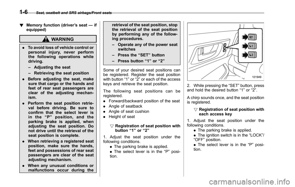
2. While pressing the “SET”button, press
and hold the desired button “1 ” or “2”.
A chirp sounds once, and the seat position
is registered. !Registration of seat position with
each access key
1. Adjust the seat position under the
following conditions. .The parking brake is applied.
. The ignition switch is in the “LOCK”/
“OFF ”position.
. The select lever is in the “P”posi-
tion.
1-6
Page 40 of 610

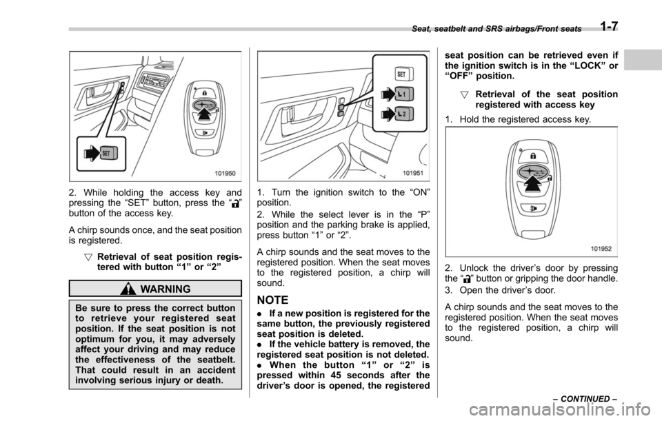
2. While holding the access key and
pressing the“SET”button, press the “”
button of the access key.
A chirp sounds once, and the seat position
is registered.
!Retrieval of seat position regis-
tered with button “1 ” or “2 ”
WARNING
Be sure to press the correct button
to retrieve your registered seat
position. If the seat position is not
optimum for you, it may adversely
affect your driving and may reduce
the effectiveness of the seatbelt.
That could result in an accident
involving serious injury or death.
1. Turn the ignition switch to the “ON ”
position.
2. While the select lever is in the “P ”
position and the parking brake is applied,
press button “1”or “2”.
A chirp sounds and the seat moves to the
registered position. When the seat moves
to the registered position, a chirp will
sound.
NOTE
. If a new position is registered for the
same button, the previously registered
seat position is deleted.
. If the vehicle battery is removed, the
registered seat position is not deleted.
. When the button “1 ” or “2 ” is
pressed within 45 seconds after the
driver ’s door is opened, the registered seat position can be retrieved even if
the ignition switch is in the
“LOCK ”or
“ OFF ”position.
! Retrieval of the seat position
registered with access key
1. Hold the registered access key.
2. Unlock the driver ’s door by pressing
the “”button or gripping the door handle.
3. Open the driver ’s door.
A chirp sounds and the seat moves to the
registered position. When the seat moves
to the registered position, a chirp will
sound.
Seat, seatbelt and SRS airbags/Front seats
–CONTINUED –1-7
Page 41 of 610

Seat, seatbelt and SRS airbags/Front seats
NOTE
.If the registered seat position cannot
be retrieved after performing the pre-
vious procedures, try the following
procedures.
(1) Press the “SET ”button on the
driver ’s door.
(2) Press the “
”button on the
access key or touch the door lock
sensor to lock the doors.
(3) Perform the prior procedures
again.
. If the keyless access function is
disabled, the seat position cannot be
retrieved by gripping the driver ’s door
handle. However, the seat position can
still be retrieved by pressing the “
”
button on the access key. For informa-
tion about how to enable/disable the
keyless access function, refer to “Dis-
abling keyless access function” F2-18.
. If a new position is registered for the
same access key, the previously regis-
tered seat position is deleted.
! Clearing the registered seat
position with access key
1. Close the driver ’s door.
2. While holding the access key and
pressing the “SET”button, press the “
”
button on the access key. A chirp will sound, and the registered seat
position will be cleared.
&
Head restraint adjustment
WARNING
. Never drive the vehicle with the
head restraints removed because
they are designed to reduce the
risk of serious neck injury in the
event that the vehicle is struck
from the rear. Also, never install
the head restraints the opposite
way around. Doing so will pre-
vent the head restraints from
functioning as intended. There-
fore, when you remove the head
restraints, you must reinstall all
head restraints correctly to pro-
tect vehicle occupants.
. All occupants, including the dri-
ver, should not operate a vehicle
or sit in a vehicle ’s seat until the
head restraints are placed in their
proper positions in order to mini-
mize the risk of neck injury in the
event of a crash.
Both the driver ’s seat and front passen-
ger ’s seat are equipped with head re-
straints. Both head restraints are adjusta-
ble in the following ways. !
Head restraint height adjustment
1) Head restraint
2) Release button
To raise:
Pull the head restraint up.
To lower:
Push the head restraint down while
pressing the release button on the top of
the seatback.
To remove:
While pressing the release button, pull out
the head restraint.
To install:
Install the head restraint into the holes that
are located on the top of the seatback until
the head restraint locks. Press and hold
the release button to lower the head
restraint.
1-8