2017 SUBARU LEGACY ECO mode
[x] Cancel search: ECO modePage 224 of 610

1) HomeLink®button 1
2) HomeLink®button 2
3) HomeLink®button 3
1. Press and hold the two outer buttons
(button 1 and button 3) until the indicator
light begins to flash (after approximately
20 seconds).
2. Release both buttons.
!In case a problem occurs
If you cannot activate a device using the
corresponding HomeLink
®button after
programming, contact HomeLink®at
www.homelink.com or call 1-800-355-
3515 for assistance.
& Auto-dimming mirror with
HomeLink
®(except U.S.-
spec. models - if equipped)
1) HomeLink®button 1
2) HomeLink®button 2
3) LED
4) HomeLink
®button 3
5) Sensor
6) Automatic dimming on button
7) Automatic dimming off button
The auto-dimming mirror has an anti-glare
feature which automatically reduces glare
coming from headlights of vehicles behind
you. It also contains a HomeLink
®wireless
control system.
By pressing the automatic dimming on/off
button, the automatic dimming function is
turned on or off. When the automatic dimming function is on, the LED indicator
will illuminate.
Even with the mirror in the automatic
dimming mode, the mirror surface turns
bright if the shift lever/select lever is
shifted into the
“R ”(reverse) position. This
is to ensure good rearward visibility during
reversing.
When cleaning the mirror, use a paper
towel or similar material dampened with
glass cleaner. Do not spray glass cleaner
directly on the mirror as that may cause
the liquid cleaner to enter the mirror
housing and damage the mirror.
! Photosensors
The mirror has a photosensor attached on
both the front and back sides. During
nighttime driving, these sensors detect
Instruments and controls/Mirrors
–CONTINUED –3-69
Page 230 of 610

!To Operate the Auto-Dimming Fea-
ture
Press the “
”switch to turn the auto-
dimming feature on/off. The auto-dimming
feature is enabled when the switch ’s
green LED indicator is on. The auto-
dimming feature will default to on with
each ignition cycle.
! To Operate the Compass Feature
1. To turn the compass feature on/off,
press and hold the “
”switch for more
than 3 seconds or until the display turns
on/off. The compass feature will default to
on with each ignition cycle.
2. If the display reads “C”, slowly drive
the vehicle in circles until compass is
calibrated.
Compass calibration zones
3. To adjust for compass zone variance:
(1) Find your current location and
zone number on the map.
(2) Press and hold the “
”switch for
more than 6 seconds or until a zone
number appears in the display.
(3) Once the zone number appears in
the display, toggle the “
”switch
again until your current location zone
number appears. After you stop press-
ing the switch, your new zone number
will be saved. Within a few seconds,
the display will show a compass
direction.
4. If the vehicle’ s magnetics have chan-
ged or if the compass appears inaccurate,
recalibrate the compass. Press and hold
the “
”switch for more than 9 seconds or
until a “C”appears in the display. Once a
“C ”appears in the display, slowly drive the
vehicle in circles until compass is cali-
brated.
! HomeLink
®Wireless Control Sys-
tem
The HomeLink
®Wireless Control System
provides a convenient way to replace up
to three hand-held radiofrequency re-
motes used to activate devices such as
gate operators, garage door openers,
entry door locks, security systems, even
home lighting. The below steps are generic programming instructions; for
Genie and Sommer garage door openers
please go directly to the HomeLink
®website. Additional information and pro-
gramming videos can be found at
www.HomeLink.com and
www.youtube.com/HomeLinkGentex.
CAUTION
.
Before programming HomeLink®to a garage door opener or gate
operator, make sure that people
and objects are out of the way of
the device to prevent potential
harm or damage.
. When programming a garage
door opener, it is advised to park
outside of the garage.
. Do not use HomeLink
®with any
garage door opener that lacks
safety stop and reverse features
as required by U.S. federal safety
standards (this includes any gar-
age door opener model manufac-
tured before April 1, 1982). A
garage door that cannot detect
an object signaling the door to
stop and reverse does not meet
current U.S. federal safety stan-
dards.
. It is also recommended that a
Instruments and controls/Mirrors
–CONTINUED –3-75
Page 235 of 610

Instruments and controls/Mirrors
online at www.HomeLink.com and
www.youtube.com/HomeLinkGentex.!Using Two-Way Communication
1) Status Indicator
Recall and display (at any time) the last
recorded garage door status message
communicated to HomeLink
®by simulta-
neously pressing HomeLink®buttons 1
and 2 for 2 seconds. HomeLink®will
display the last recorded status for 3
seconds.
If two-way communication programming is
successful, HomeLink
®will display the
status of your garage door opener with
arrow indicators (see below).
1) Garage Door Opener CLOSING (Blink- ing Orange)
2) Garage Door Opener CLOSED (Solid Green)
3) Garage Door Opener OPENING (Blink- ing Orange)
4) Garage Door Opener OPENED (Solid Green)
!Certification
In the event that there are still program-
ming difficulties or questions, additional
HomeLink
®information and programming
videos can be found at
www.HomeLink.com,
www.youtube.com/HomeLinkGentex, or
by calling the toll-free HomeLink-hotline
at 1-800-355-3515. .
U.S.-spec. models
FCC ID: NZLAECHL5
CAUTION
FCC WARNING
Changes or modifications not ex-
pressly approved by the party re-
sponsible for compliance could void
the user ’s authority to operate the
equipment.
This device complies with part 15 of the
FCC Rules. Operation is subject to the
following two conditions: (1) This de-
vice may not cause harmful interfer-
ence, and (2) this device must accept
any interference received, including
interference that may cause undesired
operation.
3-80
Page 245 of 610

Climate control/Manual climate control
and become damaged, the system may
not be able to control the interior tempera-
ture correctly. To avoid damaging the
sensors, observe the following precau-
tions:
–Do not subject the sensors to impact.
– Keep water away from the sensors.
– Do not cover the sensors.
The sensors are located as follows:
– Solar sensor: beside the speaker grille
on the dashboard
– Interior air temperature sensor: on the
side of the driver-side part of the center
panel
– Outside temperature sensor: behind
front grille.Manual climate control
& Airflow mode selection
Select the preferred airflow mode by
pressing the airflow mode selection button
or defroster button.
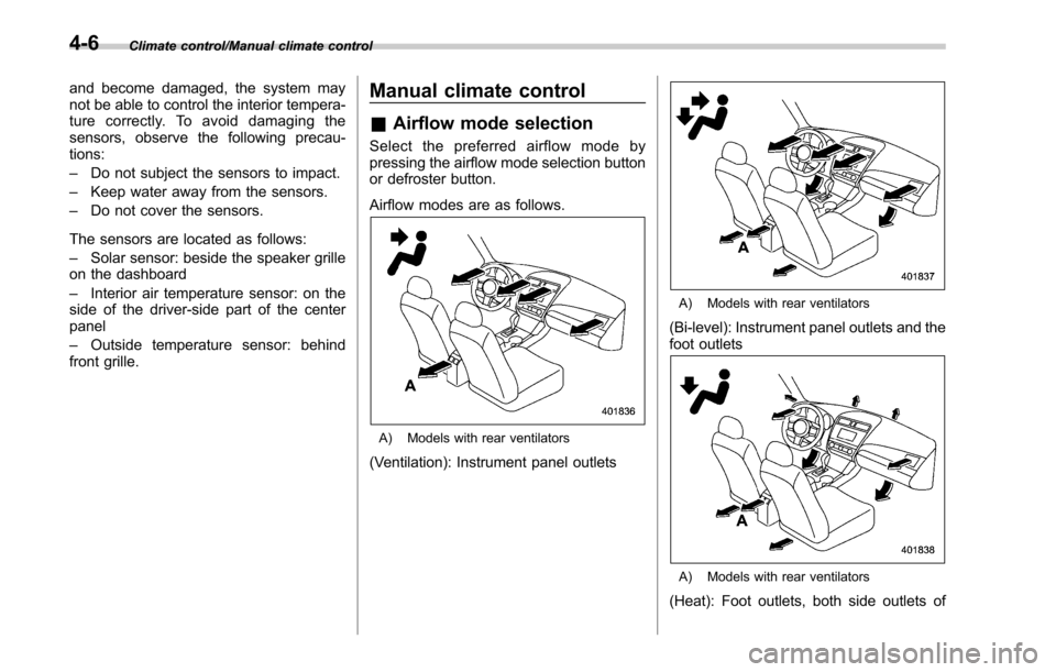
Airflow modes are as follows.
A) Models with rear ventilators
(Ventilation): Instrument panel outlets
A) Models with rear ventilators
(Bi-level): Instrument panel outlets and the
foot outlets
A) Models with rear ventilators
(Heat): Foot outlets, both side outlets of
4-6
Page 267 of 610

Audio/Audio set
!Touch screen operation
This system is operated mainly by the
keys on the screen.
When a screen key is touched, a beep
sounds. You can set the beep sound.
Refer to “Unit settings” F5-19.
NOTE
. If the system does not respond to
touching a screen key, move your
finger away from the screen and touch
it again.
. Grayed-out screen keys cannot be
operated.
. The displayed image may become
darkerandmovingimagesmaybe
slightly distorted when the screen is
cold.
. In extremely cold conditions, the
screen may not be displayed correctly.
Also, the screen keys may be less
responsive than usual when pressed.
. When you look at the screen
through polarized material such as
polarized sunglasses, the screen may
be dark and difficult to see. If so, look at
the screen from different angles, adjust
the screen settings or take off your
sunglasses. Refer to “Unit settings ”
F 5-19. !
Entering letters and numbers/list
screen operation
! Entering letters and numbers
When entering the Bluetooth device name
or PIN-code, or the phone number, letters
and numbers can be entered via the
screen.
Enter letters (example: In-Car-Device
setting)
No. Function
&1Enter the desired characters (alpha-
bet key mode).
&2Switch to the screen for characters.
&3Enter a space.
&4Confirm the characters/numbers en-
tered into the window. No. Function
&5Delete a character/number entered
into the window.
!
List screen
Multimedia playlists (example: iPod play-
list)
No. Function
&1Select a category that wants to play
back.
&2Return to the playback display of
each mode.
&3Select to skip to the next or previous
page.
5-16
Page 268 of 610

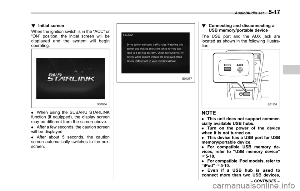
!Initial screen
When the ignition switch is in the “ACC”or
“ON ”position, the initial screen will be
displayed and the system will begin
operating.
. When using the SUBARU STARLINK
function (if equipped), the display screen
may be different from the screen above.
. After a few seconds, the caution screen
will be displayed.
. After about 5 seconds, the caution
screen automatically switches to the next
screen.
! Connecting and disconnecting a
USB memory/portable device
The USB port and the AUX jack are
located as shown in the following illustra-
tion.
NOTE
. This unit does not support commer-
cially available USB hubs.
. Turn on the power of the device
when it is not turned on.
. This device has a USB port for USB
memory/portable device.
. For compatible USB memory de-
vices, refer to “USB memory device ”
F 5-10.
. For compatible iPod models, refer to
“ iPod ”F 5-10.
. Even if a USB hub is used to
connect more than two USB devices,
Audio/Audio set
–CONTINUED –5-17
Page 269 of 610

Audio/Audio set
only the first two connected devices
will be recognized.
&Basic operation
This section describes some of the basic
features of the audio/visual system. Some
information may not pertain to your sys-
tem.
Your audio/visual system works when the
ignition switch is turned to the “ACC”or
“ON ”position.
CAUTION
To prevent the battery from being
discharged, do not leave the audio/
visual system on longer than neces-
sary when the engine is not running.
NOTE
Some functions can also be operated
by using the voice command system.
For details, refer to “Voice command
system ”F 5-81. !
Turning the system on and off
Press the power/VOLUME knob to turn
the audio/visual system on and off. When
the system turns on, the mode that was in
use the last time the system was turned off
will be displayed. Press and hold the knob
to turn the display off.
Turn this knob to adjust the volume. !
Selecting an audio source
1. Press the AUDIO/TUNE knob.
2. Select the desired source.
Example: Source select screen
5-18
Page 279 of 610

Audio/Audio set
&AM/FM radio
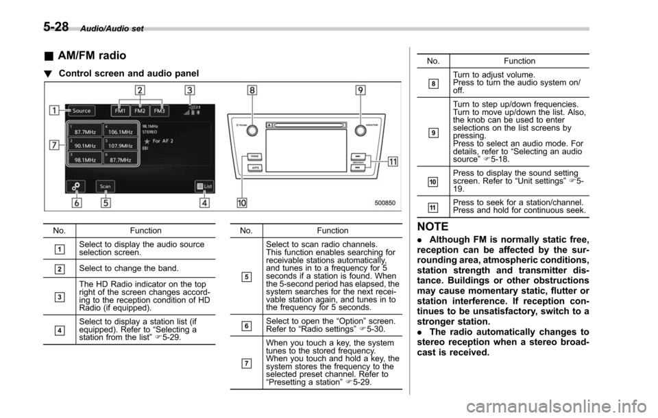
! Control screen and audio panel
No. Function
&1Select to display the audio source
selection screen.
&2Select to change the band.
&3
The HD Radio indicator on the top
right of the screen changes accord-
ing to the reception condition of HD
Radio (if equipped).
&4Select to display a station list (if
equipped). Refer to“Selecting a
station from the list ”F 5-29. No. Function
&5
Select to scan radio channels.
This function enables searching for
receivable stations automatically,
and tunes in to a frequency for 5
seconds if a station is found. When
the 5-second period has elapsed, the
system searches for the next recei-
vable station again, and tunes in to
the frequency for 5 seconds.
&6Select to open the
“Option ”screen.
Refer to “Radio settings ”F 5-30.
&7
When you touch a key, the system
tunes to the stored frequency.
When you touch and hold a key, the
system stores the frequency to the
selected preset channel. Refer to
“Presetting a station ”F 5-29. No. Function
&8Turn to adjust volume.
Press to turn the audio system on/
off.
&9
Turn to step up/down frequencies.
Turn to move up/down the list. Also,
the knob can be used to enter
selections on the list screens by
pressing.
Press to select an audio mode. For
details, refer to
“Selecting an audio
source ”F 5-18.
&10Press to display the sound setting
screen. Refer to “Unit settings ”F 5-
19.
&11Press to seek for a station/channel.
Press and hold for continuous seek.
NOTE
. Although FM is normally static free,
reception can be affected by the sur-
rounding area, atmospheric conditions,
station strength and transmitter dis-
tance. Buildings or other obstructions
may cause momentary static, flutter or
station interference. If reception con-
tinues to be unsatisfactory, switch to a
stronger station.
. The radio automatically changes to
stereo reception when a stereo broad-
cast is received.
5-28