2017 SUBARU LEGACY ESP
[x] Cancel search: ESPPage 343 of 610

Audio/Appendix
Appendix
&Certification
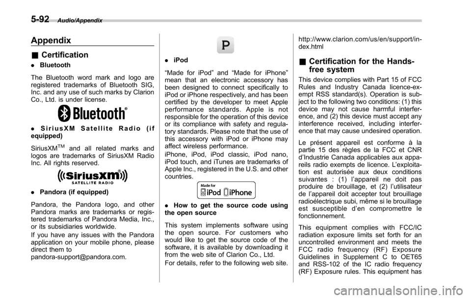
. Bluetooth
The Bluetooth word mark and logo are
registered trademarks of Bluetooth SIG,
Inc. and any use of such marks by Clarion
Co., Ltd. is under license.
. SiriusXM Satellite Radio (if
equipped)
SiriusXM
TMand all related marks and
logos are trademarks of SiriusXM Radio
Inc. All rights reserved.
. Pandora (if equipped)
Pandora, the Pandora logo, and other
Pandora marks are trademarks or regis-
tered trademarks of Pandora Media, Inc.,
or its subsidiaries worldwide.
If you have any issues with the Pandora
application on your mobile phone, please
direct them to
[email protected].
. iPod
“Made for iPod ”and “Made for iPhone”
mean that an electronic accessory has
been designed to connect specifically to
iPod or iPhone respectively, and has been
certified by the developer to meet Apple
performance standards. Apple is not
responsible for the operation of this device
or its compliance with safety and regula-
tory standards. Please note that the use of
this accessory with iPod or iPhone may
affect wireless performance.
iPhone, iPod, iPod classic, iPod nano,
iPod touch, and iTunes are trademarks of
Apple Inc., registered in the U.S. and other
countries.
. How to get the source code using
the open source
This system implements software using
the open source. For customers who
would like to get the source code of the
software, it is available by downloading it
from the web site of Clarion Co., Ltd.
For details, refer to the following web site. http://www.clarion.com/us/en/support/in-
dex.html
&
Certification for the Hands-
free system
This device complies with Part 15 of FCC
Rules and Industry Canada licence-ex-
empt RSS standard(s). Operation is sub-
ject to the following two conditions: (1) this
device may not cause harmful interfer-
ence, and (2) this device must accept any
interference received, including interfer-
ence that may cause undesired operation.
Le présent appareil est conforme à la
partie 15 des règles de la FCC et CNR
d’Industrie Canada applicables aux appa-
reils radio exempts de licence. L ’exploita-
tion est autorisée aux deux conditions
suivantes : (1) l ’appareil ne doit pas
produire de brouillage, et (2) l ’utilisateur
de l ’appareil doit accepter tout brouillage
radioélectrique subi, même si le brouillage
est susceptible d ’en compromettre le
fonctionnement.
This equipment complies with FCC/IC
radiation exposure limits set forth for an
uncontrolled environment and meets the
FCC radio frequency (RF) Exposure
Guidelines in Supplement C to OET65
and RSS-102 of the IC radio frequency
(RF) Exposure rules. This equipment has
5-92
Page 344 of 610

very low levels of RF energy that it
deemed to comply without maximum
permissive exposure evaluation (MPE).
Cet équipement est conforme aux limites
d’exposition aux rayonnements énoncées
pour un environnement non contrôlé et
respecte les lignes directrices d ’exposition
aux fréquences radioélectriques de la
FCC dans le Supplément C à OET65 et
d ’exposition aux fréquences radioélectri-
ques (RF) CNR-102 de l ’IC. Cet équipe-
ment émet une énergie RF très faible qui
est considérée conforme sans évaluation
de l ’exposition maximale autorisée.
FCC CAUTION
Changes or modifications not expressly
approved by the party responsible for
compliance could void the user ’s authority
to operate the equipment.
This transmitter must not be co-located or
operated in conjunction with any other
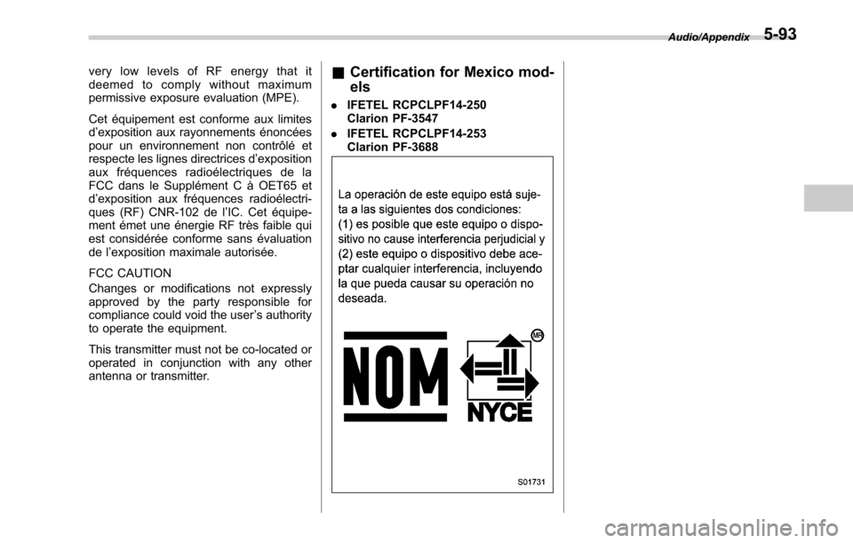
antenna or transmitter.& Certification for Mexico mod-
els
. IFETEL RCPCLPF14-250
Clarion PF-3547
. IFETEL RCPCLPF14-253
Clarion PF-3688
Audio/Appendix5-93
Page 355 of 610

Interior equipment/Accessory power outlets
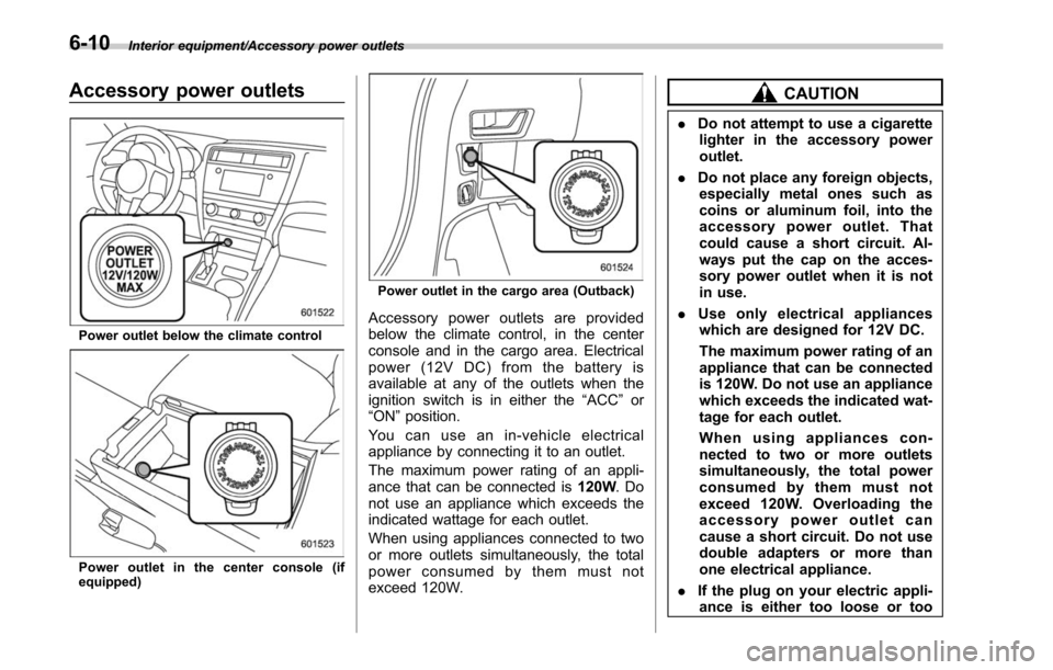
Accessory power outlets
Power outlet below the climate control
Power outlet in the center console (if
equipped)
Power outlet in the cargo area (Outback)
Accessory power outlets are provided
below the climate control, in the center
console and in the cargo area. Electrical
power (12V DC) from the battery is
available at any of the outlets when the
ignition switch is in either the“ACC”or
“ON ”position.
You can use an in-vehicle electrical
appliance by connecting it to an outlet.
The maximum power rating of an appli-
ance that can be connected is 120W.Do
not use an appliance which exceeds the
indicated wattage for each outlet.
When using appliances connected to two
or more outlets simultaneously, the total
power consumed by them must not
exceed 120W.
CAUTION
. Do not attempt to use a cigarette
lighter in the accessory power
outlet.
. Do not place any foreign objects,
especially metal ones such as
coins or aluminum foil, into the
accessory power outlet. That
could cause a short circuit. Al-
ways put the cap on the acces-
sory power outlet when it is not
in use.
. Use only electrical appliances
which are designed for 12V DC.
The maximum power rating of an
appliance that can be connected
is 120W. Do not use an appliance
which exceeds the indicated wat-
tage for each outlet.
When using appliances con-
nected to two or more outlets
simultaneously, the total power
consumed by them must not
exceed 120W. Overloading the
accessory power outlet can
cause a short circuit. Do not use
double adapters or more than
one electrical appliance.
. If the plug on your electric appli-
ance is either too loose or too
6-10
Page 376 of 610

1) Legacy
2) Outback
3. Open the fuel filler lid.
WARNING
Before opening the fuel filler cap,
first touch the vehicle body or a
metal portion of the fuel pump or
similar object to discharge any
static electricity that may be present
on your body. If your body is carry-
ing an electrostatic charge, there is
a possibility that an electric spark
could ignite the fuel, which could
burn you. To avoid acquiring a new
static electric charge, do not get
back into the vehicle while refueling
is in progress.
1) Open
2) Close
4. Remove the fuel filler cap by turning it
slowly counterclockwise.
WARNING
.Gasoline vapor is highly flam-
mable. Before refueling, always
first stop the engine and close all
vehicle doors and windows.
Make sure that there are no
lighted cigarettes, open flames
or electrical sparks in the adja-
cent area. Refueling must be
performed outside. Quickly wipe
up any spilled fuel.
. When opening the cap, grasp it
firmly and turn it slowly to the left. Do not remove the cap
quickly. Fuel may be under pres-
sure and spray out of the fuel
filler neck, especially in hot
weather. If you hear a hissing
sound while you are removing
the cap, wait for the sound to
stop and then slowly open the
cap to prevent fuel from spraying
out and creating a fire hazard.
5. Set the fuel filler cap on the cap holder
inside the fuel filler lid.
WARNING
.
When refueling, insert the fuel
nozzle securely into the fuel filler
pipe. If the nozzle is lifted or not
fully inserted, its automatic stop-
Starting and operating/Fuel
–CONTINUED –7-5
Page 378 of 610

as a result of an empty tank
could cause damage to the en-
gine. Continuing to operate your
vehicle at an extremely low fuel
level may result in a reduction of
engine performance.State emission testing (U.S.
only)
WARNING
Testing of an All-Wheel Drive model
must NEVER be performed on a
single two-wheel dynamometer. At-
tempting to do so will result in
uncontrolled vehicle movement and
may cause an accident or injuries to
persons nearby.
CAUTION
.At state inspection time, remem-
ber to tell your inspection or
service station in advance not to
place your SUBARU AWD vehicle
on a two-wheel dynamometer.
Otherwise, serious transmission
damage will result.
. Resultant vehicle damage due to
improper testing is not covered
under the SUBARU Limited War-
ranty and is the responsibility of
the state inspection program or
its contractors or licensees.
California and a number of federal states have Inspection/Maintenance programs to
inspect your vehicle
’s emission control
system. If your vehicle does not pass this
test, some states may deny renewal of
your vehicle’ s registration.
Your vehicle is equipped with a computer
that monitors the performance of the
engine’ s emission control system. Certi-
fied emission inspectors will inspect the
On-Board Diagnostic (OBDII) system as
part of the state emission inspection
process. The OBDII system is designed
to detect engine and transmission pro-
blems that might cause the vehicle emis-
sions to exceed allowable limits. OBDII
inspections apply to all 1996 model year
and newer passenger cars and trucks.
Over 30 states plus the District of Colum-
bia have implemented emission inspec-
tion of the OBDII system.
. The inspection of the OBDII system
consists of a visual operational check of
the “CHECK ENGINE ”warning light/mal-
function indicator light (MIL) and an
examination of the OBDII system with an
electronic scan tool.
. A vehicle
passes the OBDII system
inspection if proper operation of the
“CHECK ENGINE ”warning light is ob-
served, there are no stored diagnostic
trouble codes, and the OBDII readiness
monitors are all complete.
Starting and operating/State emission testing (U.S. only)
–CONTINUED –7-7
Page 393 of 610

Starting and operating/Remote engine start system (dealer option)
1. Remove the small phillips screw lo-
cated on the back side of the transmitter.
2. Carefully pry the remote engine start
transmitter halves apart using a small flat-
head screwdriver.
3. Remove the circuit board from the
bottom half of the case and remove the
battery and replace with a new one. Be
sure to observe the (+) sign on the old
battery before removing it to ensure that
the new battery is inserted properly(battery
“+”should be pointed away from
the transmitter circuit board on the bat-
tery).
4. Carefully snap the case halves back
together, reinstall the phillips screw and
test the remote engine start system.
NOTE
. This device complies with Part 15 of
the FCC Rules and with RSS-210 of
Industry Canada. Operation is subject
to the following two conditions: (1) This
device may not cause harmful inter-
ference, and (2) this device must
accept any interference received, in-
cluding interference that may cause
undesired operation.
Changes or modifications not ex-
pressly approved by the party respon-
sible for compliance could void the
user ’s authority to operate the equip-
ment and void warranty.
. To comply with the FCC RF expo-
sure compliance requirements, no
change to the antenna or the device is
permitted. Any change to the antenna
or the device could result in the device
exceeding the RF exposure require-
ments and void user ’s authority to
operate the device.
7-22
Page 397 of 610

Starting and operating/Continuously variable transmission
.Immediately after transmission fluid
is replaced, you may feel that the
transmission operation is somewhat
unusual. This results from invalidation
of data which the on-board computer
has collected and stored in memory to
allow the transmission to shift at the
most appropriate times for the current
condition of your vehicle. Optimized
shifting will be restored as the vehicle
continues to be driven for a while.
. When driving under continuous hea-
vy load conditions such as towing a
camper or climbing a long, steep hill,
the engine speed, vehicle speed and air
conditioning system cooling perfor-
mance may automatically be reduced.
This is not a malfunction. This phe-
nomenon results from the engine con-
trol function maintaining the cooling
performance of the vehicle. The engine
and vehicle speed will return to a
normal speed when the engine is able
to maintain the optimum cooling per-
formance after the heavy load de-
creases. Driving under a heavy load
must be performed with extreme care.
Do not try to pass a vehicle in front
when driving on an uphill slope while
towing.
. The continuously variable transmis-
sion is a chain type system that
provides superior transmission effi- ciency for maximum fuel economy. At
times, depending on varying driving
conditions, a chain operating noise
may be heard that is characteristic of
this type of system.
&
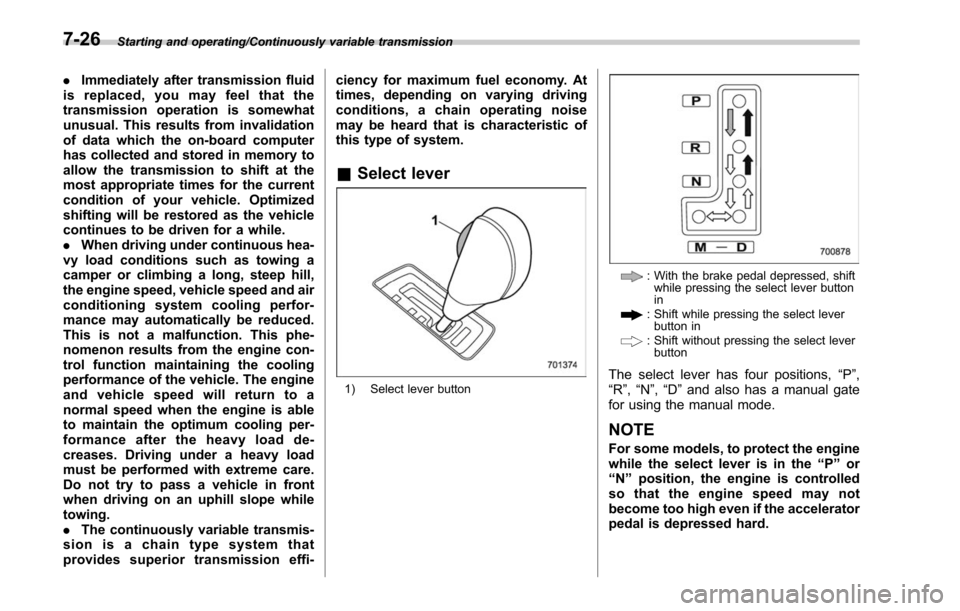
Select lever
1) Select lever button
: With the brake pedal depressed, shift
while pressing the select lever button
in
: Shift while pressing the select leverbutton in
: Shift without pressing the select leverbutton
The select lever has four positions, “P”,
“R ”,“N ”,“D ”and also has a manual gate
for using the manual mode.
NOTE
For some models, to protect the engine
while the select lever is in the “P ” or
“ N ” position, the engine is controlled
sothattheenginespeedmaynot
become too high even if the accelerator
pedal is depressed hard.
7-26
Page 398 of 610

!P (Park)
This position is for parking the vehicle and
starting the engine. In this position, the
transmission is mechanically locked to
prevent the vehicle from rolling freely.
When you park the vehicle, first apply the
parking brake, then shift into the “P ”
position. Do not hold the vehicle with only
the mechanical friction of the transmis-
sion.
To shift the select lever from the “P”to any
other position, you should depress the
brake pedal fully then move the select
lever. This prevents the vehicle from
lurching when it is started.
! R (Reverse)
This position is for backing the vehicle. To
shift from the “N”to “R”position, stop the
vehicle completely then move the lever to
the “R”position while pressing the select
lever button in.
When the ignition switch has been turned
to the “LOCK”/ “OFF ”position, movement
of the select lever from the “N”to “R”
position is possible for a limited time
period by depressing the brake pedal,
and then it becomes impossible. For
details, refer to “Shift lock function ”F 7-28. !
N (Neutral)
This position is for restarting a stalled
engine. In this position, the transmission is
neutral, meaning that the wheels and
transmission are not locked. Therefore,
the vehicle will roll freely, even on the
slightest incline unless the parking brake
or foot brake is applied.
Avoid coasting with the transmission in
neutral. Engine braking has no effect in
this condition.
WARNING
Do not drive the vehicle with the
select lever in the “N ” (neutral)
position. Engine braking has no
effect in this condition and the risk
of an accident is consequently in-
creased.
NOTE
If the select lever is in the “N ” position
when you stop the engine for parking,
you may not subsequently be able to
move it to the “R ” and “P ” positions. If
this happens, turn the ignition switch to
the “ON ”position. You will then be able
to move the select lever to the “P ”
position. !
D (Drive)
This position is for normal driving. The
transmission shifts automatically and con-
tinuously into a suitable gear according to
the vehicle speed and the acceleration
you require. Also, while driving up and
down a hill, the transmission assists and
controls the driving performance and
engine braking while corresponding to
the road grade.
When more acceleration is required in “D”
position, depress the accelerator pedal
fully to the floor and hold that position. The
transmission will automatically downshift.
In this case, the transmission will operate
like a conventional automatic transmis-
sion. When you release the pedal, the
transmission will return to the original gear
position.
To use the manual mode, move the lever
from this position into the manual gate.
!While climbing a grade
When driving up a hill, undesired upshift is
prevented from taking place when the
accelerator is released. This minimizes
the chance of subsequent downshifting to
a lower gear when accelerating again.
This prevents repeated upshifting and
downshifting resulting in a smoother op-
eration of the vehicle.
Starting and operating/Continuously variable transmission
–CONTINUED –7-27