2017 SUBARU LEGACY brake
[x] Cancel search: brakePage 179 of 610

Instruments and controls/Warning and indicator lights
.The steering wheel remains in the
fully turned position for a long period
of time.
At this time, there will be more resis-
tance when steering. However this is
not a malfunction. Normal steering
force will be restored after the steering
wheel is not operated for a while and
the power steering control system has
an opportunity to cool down. However,
if the power steering is operated in a
non-standard way which causes power
assist limitation to occur too fre-
quently, that may result in a malfunc-
tion of the power steering control
system.
&Vehicle Dynamics
Control warning light/
Vehicle Dynamics Con-
trol operation indicator
light
! Vehicle Dynamics Control warning
light
CAUTION
The Vehicle Dynamics Control sys-
tem provides its ABS control
through the electrical circuit of the ABS. Accordingly, if the ABS is
inoperative, the Vehicle Dynamics
Control system becomes unable to
provide ABS control. As a result, the
Vehicle Dynamics Control system
becomes inoperative, causing the
warning light to illuminate. Although
both the Vehicle Dynamics Control
and ABS are inoperative in this
case, the ordinary functions of the
brake system are still available. You
will be safe while driving in this
condition, but drive carefully and
have your vehicle checked at a
SUBARU dealer as soon as possi-
ble.
NOTE
.
If the electrical circuit of the Vehicle
Dynamics Control system itself mal-
functions, the warning light only illumi-
nates. At this time, the ABS (Anti-lock
Brake System) remains fully opera-
tional.
. The warning light illuminates when
the electronic control system of the
ABS/Vehicle Dynamics Control system
malfunctions.
The Vehicle Dynamics Control system is
probably inoperative under any of the
following conditions. Have your vehicle checked at a SUBARU dealer immedi-
ately.
.
The warning light does not illuminate
when the ignition switch is turned to the
“ON ”position.
. The warning light illuminates while the
vehicle is running.
NOTE
If the warning light behavior is as
described in the following examples,
the Vehicle Dynamics Control system
may be considered normal.
. The warning light illuminates right
after the engine is started but turns off
immediately and remains off.
. The warning light illuminates after
the engine has started and turns off
while the vehicle is subsequently being
driven.
. The warning light illuminates during
driving, but turns off immediately and
remains off.
! Vehicle Dynamics Control opera-
tion indicator light
The indicator light flashes during activa-
tion of the skid suppression function and
during activation of the traction control
function.
3-24
Page 184 of 610

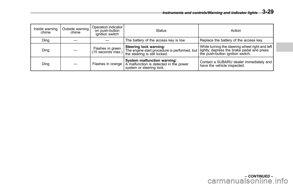
Inside warningchime Outside warning
chime Operation indicator
on push-button
ignition switch Status Action
Ding —— The battery of the access key is low. Replace the battery of the access key.
Ding —Flashes in green
(15 seconds max.) Steering lock warning:
The engine start procedure is performed, but
the steering is still locked. While turning the steering wheel right and left
lightly, depress the brake pedal and press
the push-button ignition switch.
Ding —Flashes in orange System malfunction warning:
A malfunction is detected in the power
system or steering lock. Contact a SUBARU dealer immediately and
have the vehicle inspected.
Instruments and controls/Warning and indicator lights
–CONTINUED –
3-29
Page 208 of 610

curve
–When another vehicle passes in
front of your vehicle
– When an oncoming vehicle or ve-
hicle ahead comes in and out of view
because of continuous curves, median
strips, roadside trees, etc.
. If the camera detects the light of the
front fog lights of an oncoming vehicle, the
headlight mode may change from the high
beam to the low beam automatically.
. The headlight mode may change from
the high beam to the low beam, or the low
beam mode may continue, when affected
by a street light, traffic signal, illumination
of an advertisement board, or a reflective
object such as a road sign and signboard.
. The timing of the change of headlight
mode may differ due to the following
factors.
–the vehicle condition (e.g., number
of passengers or weight of loaded
cargo)
– surrounding situation (e.g., move-
ment and direction of an oncoming
vehicle or vehicle ahead)
– detection limitations of the camera
angle& Headlight flasher
CAUTION
Do not hold the lever in the flashing
position for more than just a few
seconds.
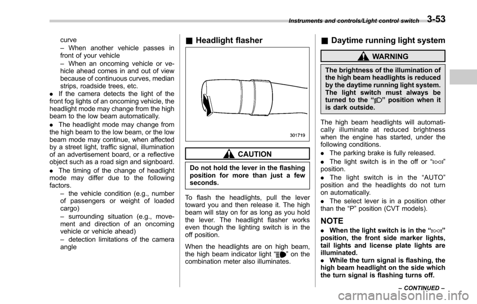
To flash the headlights, pull the lever
toward you and then release it. The high
beam will stay on for as long as you hold
the lever. The headlight flasher works
even though the lighting switch is in the
off position.
When the headlights are on high beam,
the high beam indicator light “
”on the
combination meter also illuminates.
& Daytime running light system
WARNING
The brightness of the illumination of
the high beam headlights is reduced
by the daytime running light system.
The light switch must always be
turned to the “
”position when it
is dark outside.
The high beam headlights will automati-
cally illuminate at reduced brightness
when the engine has started, under the
following conditions.
. The parking brake is fully released.
. The light switch is in the off or “
”
position.
. The light switch is in the “AUTO ”
position and the headlights do not turn
on automatically.
. The select lever is in a position other
than the “P”position (CVT models).
NOTE
. When the light switch is in the “”
position, the front side marker lights,
tail lights and license plate lights are
illuminated.
. While the turn signal is flashing, the
high beam headlight on the side which
the turn signal is flashing turns off.
Instruments and controls/Light control switch
–CONTINUED –3-53
Page 266 of 610

&Basic information before use
WARNING
When the vehicle is stopped with the
engine running, always apply the
parking brake for safety. Failure to
do so may result in loss of control of
your vehicle and cause an accident
or serious injury.
CAUTION
. To prevent damaging the screen,
touch the screen keys with your
finger lightly.
. Wipe off fingerprints using a
glass cleaning cloth. Do not use
chemical cleaners to clean the
screen, as they may damage the
touch screen. !
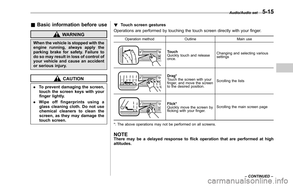
Touch screen gestures
Operations are performed by touching the touch screen directly with your finger.
Operation method OutlineMain use
Touch
Quickly touch and release
once.Changing and selecting various
settings
Drag*
Touch the screen with your
finger, and move the screen
to the desired position.
Scrolling the lists
Flick*
Quickly move the screen by
flicking with your finger.
Scrolling the main screen page
*: The above operations may not be performed on all screens.
NOTEThere may be a delayed response to flick operation that are performed at high
altitudes.
Audio/Audio set
–CONTINUED –5-15
Page 276 of 610

!Display settings
Touch the
tab to set display.
Item Function
Day/Night
Mode The
“Auto ”, “Day ”or “Night ”key
can be selected on the pop-up
screen.
When the “Auto ”key is selected,
the screen changes to day or
night mode depending on the
position of the headlight switch.
Brightness Touch
“+” or“−” to adjust the
brightness.
NOTE
. When the screen is viewed through
polarized sunglasses, a rainbow pat-
tern may appear on the screen due to
optical characteristics of the screen. If
this is disruptive, please operate the screen without polarized sunglasses.
.
If the screen is set to “Day ”mode
with the headlight switch turned on,
this condition is memorized even with
the engine turned off.
! How to adjust the rear view
image
In the camera display, the brightness, tint,
color and black level of the screen can be
adjusted.
1. Depress the brake pedal fully and stop
the vehicle.
2. While the vehicle is stopped, set the
shift lever (MT models) or select lever
(CVT models) in the “R”position, and then
touch the display.
3. Touch the “Display Adjustment ”key.
4. Touch the items to adjust the rear
camera screen.
Camera display
WARNING
When adjusting camera display
screen, make sure to depress the
brake pedal fully to avoid the vehicle
from moving. Failure to do so may
lead to a serious accident.
NOTE
The camera display can be accessed
when the rear camera monitor is dis-
played.
Audio/Audio set
–CONTINUED –5-25
Page 356 of 610

tight for the accessory power
outlet, this can result in a poor
contact or cause the plug to get
stuck. Only use plugs that fit
properly.
. Use of an electric appliance in the
accessory power outlet for a long
period of time while the engine is
not running can cause battery
discharge.
. Before driving your vehicle, make
sure that the plug and the cord
on your electrical appliance will
not interfere with your shifting
gears and operating the accel-
erator and brake pedals. If they
do, do not use the electrical
appliance while driving.
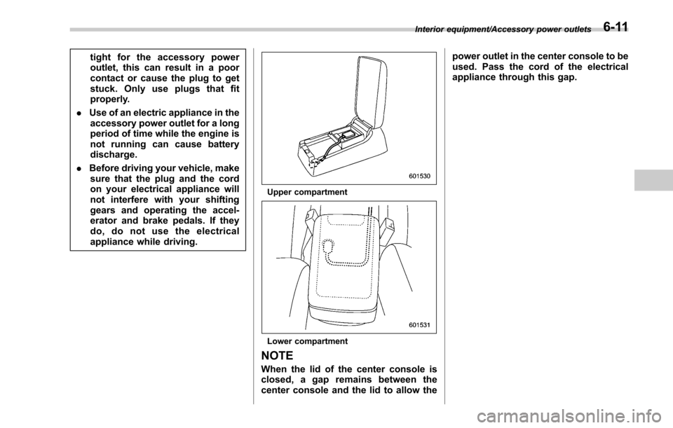
Upper compartment
Lower compartment
NOTE
When the lid of the center console is
closed, a gap remains between the
center console and the lid to allow the power outlet in the center console to be
used. Pass the cord of the electrical
appliance through this gap.
Interior equipment/Accessory power outlets6-11
Page 372 of 610

Fuel...................................................................... 7-3
Fuel requirements ............................................... 7-3
Fuel filler lid and cap ........................................... 7-4
State emission testing (U.S. only) ...................... 7-7
Preparing to drive ............................................... 7-8
Starting and stopping the engine (models without push-button ignition switch) .............. 7-9
General precautions when starting/stopping
engine .............................................................. 7-9
Starting engine ................................................... 7-10
Stopping the engine ........................................... 7-11
Steering lock ...................................................... 7-11
Starting and stopping engine (models with
push-button start system) .............................. 7-12
Safety precautions............................................. 7-12
Operating range for push-button start system ............................................................. 7-12
Starting engine ................................................... 7-12
Stopping engine ................................................. 7-14
When access key does not operate properly ....... 7-14
Steering lock ...................................................... 7-14
Remote engine start system (dealer
option) .............................................................. 7-15
Models with “keyless access with push-button
start system ”................................................... 7-16
Models without “keyless access with push-button
start system ”................................................... 7-17
Entering the vehicle while it is running via remote start ................................................................. 7-20
Entering the vehicle following remote engine start shutdown ......................................................... 7-20 Pre-heating or pre-cooling the interior of the
vehicle ............................................................ 7-20
Service mode (models without “keyless access
with push-button start system ”) ....................... 7-20
Remote transmitter program (models without “keyless access with push-button start
system ”).......................................................... 7-20
System maintenance .......................................... 7-21
Manual transmission ......................................... 7-23Selecting reverse gear ....................................... 7-23
Shifting speeds .................................................. 7-24
Driving tips ........................................................ 7-24
Continuously variable transmission ................. 7-25Select lever....................................................... 7-26
Shift lock function ............................................. 7-28
Selection of manual mode .................................. 7-29
Driving tips ........................................................ 7-31
Power steering ................................................... 7-31
Braking ............................................................... 7-32
Braking tips ....................................................... 7-32
Brake system .................................................... 7-32
Disc brake pad wear warning indicators ............. 7-33
ABS (Anti-lock Brake System).......................... 7-33
ABS self-check.................................................. 7-34
ABS warning light .............................................. 7-34
Electronic Brake Force Distribution (EBD)
system ............................................................. 7-34
Steps to take if EBD system malfunctions .......... 7-34
Vehicle Dynamics Control system.................... 7-35Vehicle Dynamics Control system monitor .......... 7-37
Vehicle Dynamics Control OFF switch ................ 7-37
Starting and operating
7
Page 373 of 610

Starting and operating
X-mode (Outback CVT models)......................... 7-38
To activate/deactivate the X-mode ....................... 7-39
Hill descent control function ............................... 7-40
Tire pressure monitoring system (TPMS) (if
equipped) ......................................................... 7-41
Parking your vehicle .......................................... 7-42
Electronic parking brake ..................................... 7-43
Parking tips ....................................................... 7-47
Hill start assist system (MT models) ................ 7-48
To activate/deactivate the Hill start assist
system ............................................................. 7-50
Cruise control ..................................................... 7-50To set cruise control .......................................... 7-50
To temporarily cancel the cruise control ............. 7-51
To turn off the cruise control .............................. 7-52
To change the cruising speed ............................. 7-52
Cruise control indicator ...................................... 7-53
Cruise control set indicator ................................ 7-53
BSD/RCTA (if equipped).................................... 7-54
System features................................................. 7-54 System operation
............................................... 7-56
BSD/RCTA approach indicator light/warning buzzer ............................................................. 7-57
BSD/RCTA warning indicator .............................. 7-59
BSD/RCTA OFF switch ....................................... 7-60
Certification for the BSD/RCTA ........................... 7-61
Handling of radar sensors .................................. 7-61
Reverse Automatic Braking System (if
equipped) ........................................................ 7-63
Reverse Automatic Braking System overview .....7-63
Operating conditions ......................................... 7-64
Reverse Automatic Braking System operation ......................................................... 7-66
Canceling the Reverse Automatic Braking system operation ......................................................... 7-69
RAB warning indicator ....................................... 7-69
Reverse Automatic Braking system ON/OFF setting ............................................................. 7-69
Handling of the sonar sensors ........................... 7-70