2017 SUBARU LEGACY trailer
[x] Cancel search: trailerPage 428 of 610
The BSD/RCTA will resume operation
once these conditions are corrected,
and the BSD/RCTA warning indicator
will disappear. However, if the BSD/
RCTA warning indicator appears for a
prolonged period of time, have the
system inspected at a SUBARU dealer
as soon as possible.
.The detectability of the radar sen-
sors is restricted. The BSD/RCTA de-
tection may be impaired and the sys-
tem may not operate properly under the
following conditions.
–When the rear bumper around
the radar sensors is distorted
– When ice, snow or mud adheres
to the rear bumper surface around
the radar sensors
– When stickers, etc. are affixed on
the areas of the radar sensors on
the rear bumper
– During adverse weather condi-
tions such as rain, snow or fog
– When driving on wet roads such
as snow-covered roads and
through puddles
. The radar sensors may not detect or
may have difficulty detecting the fol-
lowing vehicles and objects.
–Small motorcycles, bicycles, pe-
destrians, stationary objects on the
road or road side, etc. –
Vehicles with body shapes that
the radar may not reflect (vehicles
with lower body height such as a
trailer with no cargo and sports
cars)
– Vehicles that are not approach-
ing your vehicle even though they
are in the detection area (either on a
neighboring lane to the rear or
beside your vehicle when rever-
sing) (The system determines the
presence of approaching vehicles
based on data detected by the radar
sensors.)
– Vehicles traveling at significantly
different speeds
– Vehicles driving in parallel at
almost the same speed as your
vehicle for a prolonged time
– Oncoming vehicles
– Vehicles in a lane beyond the
neighboring lane
– Vehicles travelling at a signifi-
cantly lower speed that you are
trying to overtake
. On a road with extremely narrow
lanes, the system may detect vehicles
driving in a lane next to the neighbor-
ing lane.& BSD/RCTA approach indica-
tor light/warning buzzer
While the BSD/RCTA is active, the follow-
ing item(s) will operate to alert the driver:
. The BSD/RCTA approach indicator
light (when there are vehicles in the
neighboring lanes).
. The BSD/RCTA approach indicator
light and warning buzzer (when a vehicle
is approaching from the left or right side
while your vehicle is reversing)
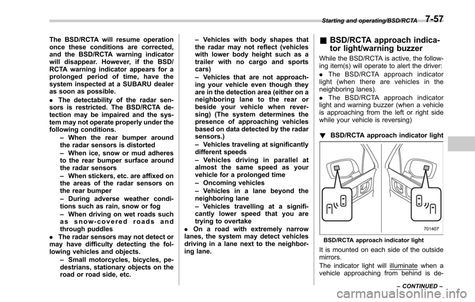
! BSD/RCTA approach indicator light
BSD/RCTA approach indicator light
It is mounted on each side of the outside
mirrors.
The indicator light will
illuminate when a
vehicle approaching from behind is de-
Starting and operating/BSD/RCTA
–CONTINUED –7-57
Page 431 of 610

Starting and operating/BSD/RCTA
!System malfunction indicator
System malfunction indicator
1) At first, this message will appear
2) Then this message will appear
This indicator appears when a malfunction
occurs in the system. Contact a SUBARU
dealer and have the system inspected.
&BSD/RCTA OFF switch
BSD/RCTA OFF switch
BSD/RCTA OFF indicator
If the BSD/RCTA OFF switch is pressed,
the BSD/RCTA OFF indicator appears on
the multi information display of the combi- nation meter, and the BSD/RCTA is
deactivated.
Press the switch again to activate the
BSD/RCTA. The BSD/RCTA OFF indica-
tor disappears.
NOTE
.
In the following cases, press the
BSD/RCTA OFF switch to deactivate
the system. The system may not oper-
ate properly due to blocked radar
waves.
–When towing a trailer
– When a bicycle carrier or other
item is fitted to the rear of the
vehicle
– When using a chassis dynam-
ometer or free roller device, etc.
– When running the engine and
making the wheels rotate while
lifting up the vehicle
. If the ignition switch is turned to the
“ LOCK ”/“ OFF ”position, the last known
status of the system is maintained. For
example, if the ignition switch is turned
to the “LOCK ”/“ OFF ”position with the
BSD/RCTA deactivated, the BSD/RCTA
remains deactivated the next time the
ignition switch is turned to the “ON ”
position.
. If the vehicle battery is disconnected
due to situations such as battery
7-60
Page 437 of 610

Starting and operating/Reverse Automatic Braking System
near the sonar sensor
–Commercial electronic parts
(fog light, fender pole, radio
antenna) or commercial at-
tachment parts (trailer hitch,
bicycle carrier, bumper guard)
are attached
– Parts that emit high frequency
sound, such as a horn or
speaker, are attached
Vehicle conditions – The vehicle is significantly
inclined
– The ground clearance is sig-
nificantly reduced due to the
vehicle’ s loading condition,
etc.
– When the sonar sensor is
misaligned due to a collision
or an accident
Surrounding environment – A cloth banner, flag, hanging
branch or railroad crossing
bars are present in the rever-
sing direction
– When reversing on a gravel or
grassy area
– When reversing in an area
where objects or walls are
adjacent to the vehicle such as narrow tunnels, narrow
bridges, narrow roads or nar-
row garages
– Wheel track or hole is present
in the ground of the reversing
direction
– When reversing over a drai-
nage cover (grating cover)
– The path of the reversing
direction is inclined such as
on a steep uphill
– A curb is present in the rever-
sing direction
– When reversing downhill
Example: The path of the reversing direc-
tion is inclined such as on a steep uphill.
NOTE
The Reverse Automatic Braking sys-
tem will operate at vehicle speed
between 1 to 9 mph (1.5 to 15 km/h).
However, stopping the vehicle by auto-
matic hard braking is designed to
operate when the vehicle speed is less
than 3 mph (5 km/h).
&Reverse Automatic Braking
System operation
When Reverse Automatic Braking System
is in operation, an audible warning beeps
will sound in 3 levels to warn the driver of
a potential collision.
1) First braking and warning:
When the system detects an object, if the
vehicle is kept reversing, the system
determines a collision with an object may
occur. In this case, short warning beeps
will sound and automatic deceleration will
be activated. Also, a warning message will
be indicated on the audio/navigation
monitor.
7-66
Page 444 of 610
New vehicle break-in driving–the first
1,000 miles (1,600 km) ..................................... 8-2
Fuel economy hints ............................................ 8-2
Engine exhaust gas (carbon monoxide) ............ 8-2
Catalytic converter .............................................. 8-3
Periodic inspections ........................................... 8-4
Driving in foreign countries ............................... 8-4
Driving tips for AWD vehicles ............................ 8-5
Off road driving ................................................... 8-6
Legacy................................................................ 8-6
Outback .............................................................. 8-6
Winter driving ...................................................... 8-8Operation during cold weather ............................. 8-8
Driving on snowy and icy roads ......................... 8-10
Corrosion protection .......................................... 8-11
Snow tires ......................................................... 8-11
Tire chains ......................................................... 8-12
Rocking the vehicle ............................................ 8-12
Loading your vehicle ......................................... 8-13
Vehicle capacity weight ...................................... 8-14
GVWR and GAWR (Gross Vehicle Weight Rating and Gross Axle Weight Rating) ........................ 8-14
Roof rack (Outback –if equipped) ...................... 8-15
Roof rails with integrated crossbars (Outback –if
equipped) ........................................................ 8-15
Trailer hitch (Outback —if equipped) .............. 8-19
Connecting a trailer ........................................... 8-20
If not towing a trailer .......................................... 8-21
Trailer towing (Legacy) ...................................... 8-22
Trailer towing (Outback) .................................... 8-22
Warranties and maintenance .............................. 8-22
Maximum load limits .......................................... 8-22
Trailer Hitches ................................................... 8-26
Connecting a trailer ........................................... 8-26
Trailer towing tips .............................................. 8-27
Driving tips
8
Page 457 of 610
Driving tips/Loading your vehicle
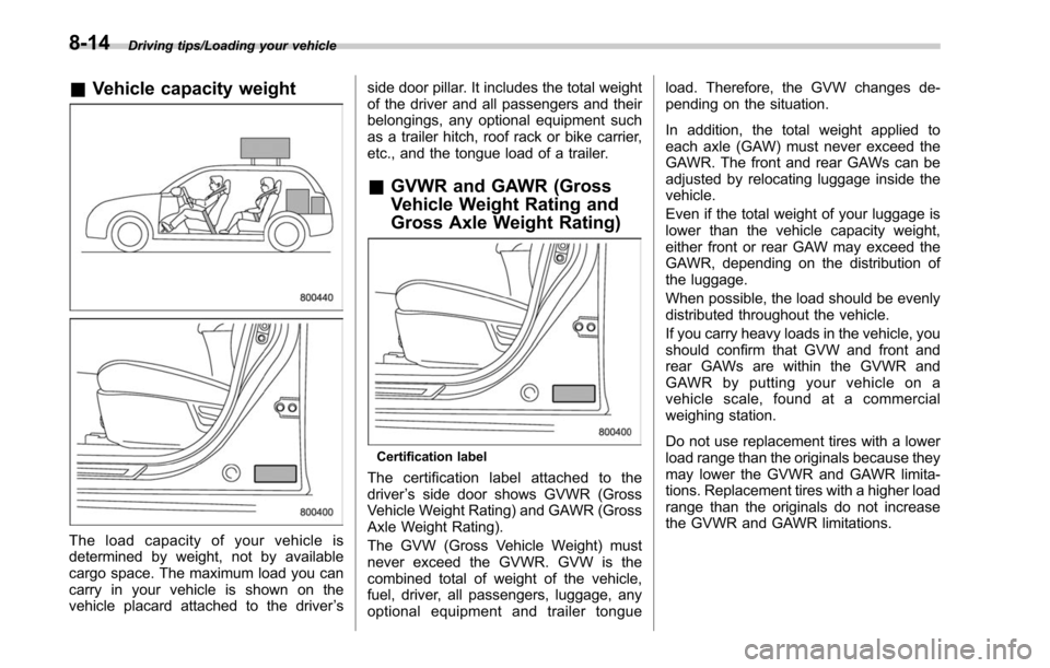
&Vehicle capacity weight
The load capacity of your vehicle is
determined by weight, not by available
cargo space. The maximum load you can
carry in your vehicle is shown on the
vehicle placard attached to the driver ’s side door pillar. It includes the total weight
of the driver and all passengers and their
belongings, any optional equipment such
as a trailer hitch, roof rack or bike carrier,
etc., and the tongue load of a trailer.
&
GVWR and GAWR (Gross
Vehicle Weight Rating and
Gross Axle Weight Rating)
Certification label
The certification label attached to the
driver ’s side door shows GVWR (Gross
Vehicle Weight Rating) and GAWR (Gross
Axle Weight Rating).
The GVW (Gross Vehicle Weight) must
never exceed the GVWR. GVW is the
combined total of weight of the vehicle,
fuel, driver, all passengers, luggage, any
optional equipment and trailer tongue load. Therefore, the GVW changes de-
pending on the situation.
In addition, the total weight applied to
each axle (GAW) must never exceed the
GAWR. The front and rear GAWs can be
adjusted by relocating luggage inside the
vehicle.
Even if the total weight of your luggage is
lower than the vehicle capacity weight,
either front or rear GAW may exceed the
GAWR, depending on the distribution of
the luggage.
When possible, the load should be evenly
distributed throughout the vehicle.
If you carry heavy loads in the vehicle, you
should confirm that GVW and front and
rear GAWs are within the GVWR and
GAWR by putting your vehicle on a
vehicle scale, found at a commercial
weighing station.
Do not use replacement tires with a lower
load range than the originals because they
may lower the GVWR and GAWR limita-
tions. Replacement tires with a higher load
range than the originals do not increase
the GVWR and GAWR limitations.
8-14
Page 462 of 610
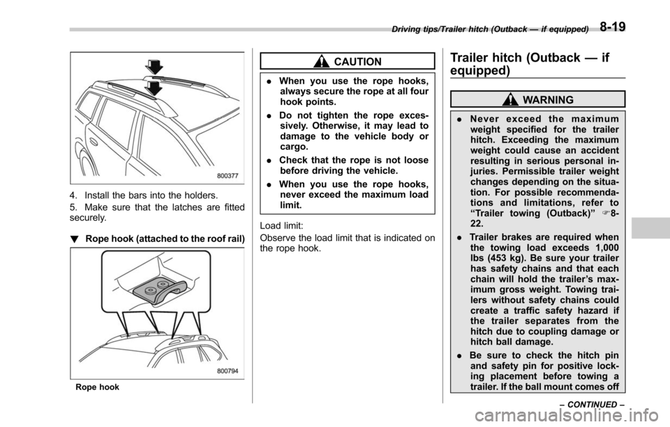
4. Install the bars into the holders.
5. Make sure that the latches are fitted
securely.
!Rope hook (attached to the roof rail)
Rope hook
CAUTION
.When you use the rope hooks,
always secure the rope at all four
hook points.
. Do not tighten the rope exces-
sively. Otherwise, it may lead to
damage to the vehicle body or
cargo.
. Check that the rope is not loose
before driving the vehicle.
. When you use the rope hooks,
never exceed the maximum load
limit.
Load limit:
Observe the load limit that is indicated on
the rope hook.
Trailer hitch (Outback —if
equipped)
WARNING
. Never exceed the maximum
weight specified for the trailer
hitch. Exceeding the maximum
weight could cause an accident
resulting in serious personal in-
juries. Permissible trailer weight
changes depending on the situa-
tion. For possible recommenda-
tions and limitations, refer to
“ Trailer towing (Outback) ”F8-
22.
. Trailer brakes are required when
the towing load exceeds 1,000
lbs (453 kg). Be sure your trailer
has safety chains and that each
chain will hold the trailer ’s max-
imum gross weight. Towing trai-
lers without safety chains could
create a traffic safety hazard if
the trailer separates from the
hitch due to coupling damage or
hitch ball damage.
. Be sure to check the hitch pin
and safety pin for positive lock-
ing placement before towing a
trailer. If the ball mount comes off
Driving tips/Trailer hitch (Outback —if equipped)
–CONTINUED –8-19
Page 463 of 610

Driving tips/Trailer hitch (Outback—if equipped)
the hitch receiver, the trailer
could get loose and create a
traffic safety hazard.
. Use only the ball mount supplied
with this hitch. Use the hitch only
as a weight carrying hitch. Do not
use with any type of weight
distributing hitch.
The maximum gross trailer weight and
maximum gross tongue weight are indi-
cated in the following table.
Maximum
gross trailer
weight Maximum
gross tongue
weight
Outback 2,700 lbs
(1,224 kg) 200 lbs
(90 kg)
When towing a trailer, refer to “Trailer
towing (Outback) ”F 8-22.
& Connecting a trailer
1. Remove the receiver cover from the
hitch receiver tube. Then insert the ball
mount into the hitch receiver tube.
2. Insert the hitch pin into the hole
located on the hitch receiver tube so that
the pin passes through the ball mount.
3. Insert the safety pin through the
provided hole on the hitch pin securely.
4. Check the ball mount assembly by
pulling on it to make sure it does not come
off the hitch receiver.
8-20
Page 464 of 610
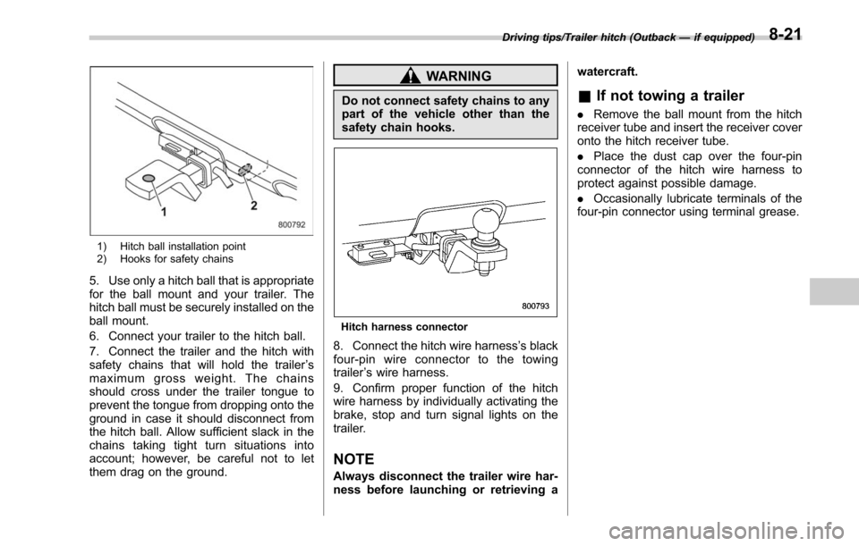
1) Hitch ball installation point
2) Hooks for safety chains
5. Use only a hitch ball that is appropriate
for the ball mount and your trailer. The
hitch ball must be securely installed on the
ball mount.
6. Connect your trailer to the hitch ball.
7. Connect the trailer and the hitch with
safety chains that will hold the trailer’s
maximum gross weight. The chains
should cross under the trailer tongue to
prevent the tongue from dropping onto the
ground in case it should disconnect from
the hitch ball. Allow sufficient slack in the
chains taking tight turn situations into
account; however, be careful not to let
them drag on the ground.
WARNING
Do not connect safety chains to any
part of the vehicle other than the
safety chain hooks.
Hitch harness connector
8. Connect the hitch wire harness ’s black
four-pin wire connector to the towing
trailer ’s wire harness.
9. Confirm proper function of the hitch
wire harness by individually activating the
brake, stop and turn signal lights on the
trailer.
NOTE
Always disconnect the trailer wire har-
ness before launching or retrieving a watercraft.
&
If not towing a trailer
. Remove the ball mount from the hitch
receiver tube and insert the receiver cover
onto the hitch receiver tube.
. Place the dust cap over the four-pin
connector of the hitch wire harness to
protect against possible damage.
. Occasionally lubricate terminals of the
four-pin connector using terminal grease.
Driving tips/Trailer hitch (Outback —if equipped)8-21