2017 SUBARU FORESTER engine control
[x] Cancel search: engine controlPage 7 of 634

Chapter 4: Climate control
This chapter informs you how to operate
the climate control.
Chapter 5: Audio
This chapter informs you how to operate
your audio system.
Chapter 6: Interior equipment
This chapter informs you how to operate
interior equipment.
Chapter 7: Starting and operating
This chapter informs you how to start and
operate your SUBARU.
Chapter 8: Driving tips
This chapter informs you how to drive your
SUBARU in various conditions and ex-
plains some safety tips on driving.
Chapter 9: In case of emergency
This chapter informs you what to do if you
have a problem while driving, such as a
flat tire or engine overheating.
Chapter 10: Appearance care
This chapter informs you how to keep your
SUBARU looking good.
Chapter 11: Maintenance and service
This chapter informs you when you need
to take your SUBARU to the dealer for
scheduled maintenance and informs you
how to keep your SUBARU running
properly.Chapter 12: Specifications
This chapter informs you about dimen-
sions and capacities of your SUBARU.
Chapter 13: Consumer information and
Reporting safety defects
This chapter informs you about Uniform
tire quality grading standards and Report-
ing safety defects.
Chapter 14: Index
This is an alphabetical listing of all that’
sin
this manual. You can use it to quickly find
something you want to read.
& Safety warnings
You will find a number of WARNINGs,
CAUTIONs and NOTEs in this manual.
These safety warnings alert you to poten-
tial hazards that could result in injury to
you or others.
Please read these safety warnings as well
as all other portions of this manual care-
fully in order to gain a better understand-
ing of how to use your SUBARU vehicle
safely.
WARNING
A WARNING indicates a situation in
which serious injury or death could
result if the warning is ignored.
CAUTION
A CAUTION indicates a situation in
which injury or damage to your
vehicle, or both, could result if the
caution is ignored.
NOTE
A NOTE gives information or sugges-
tions how to make better use of your
vehicle.
&Safety symbol
You will find a circle with a slash through it
in this manual. This symbol means “Do
not ”,“Do not do this ”,or“Do not let this
happen ”, depending upon the context.
2
Page 13 of 634

&On-road and off-road driving
This vehicle is classified as a utility
vehicle. Utility vehicles have a significantly
higher rollover rate than other types of
vehicles. Your vehicle has a higher ground
clearance and higher center of gravity,
making it more likely to roll over than
ordinary passenger cars. It also handles
and maneuvers differently from other
passenger cars. For this reason, please
read carefully the following section and
follow the instructions and precautions in
order to prevent serious injury or death
due to loss of control, rollover and other
accidents. Refer to “On-road and off-road
driving ”F 8-6.
& Attaching accessories
WARNING
. Do not attach any accessories,
labels or stickers (other than
properly placed inspection stick-
ers) to the windshield. Such
items may obstruct your view.
. If it is necessary to attach an
accessory (such as an electronic
toll collection (ETC) device or
security pass) to the windshield,
consult your SUBARU dealer for
details on the proper location.
General information
& California proposition 65
warning
WARNING
Engine exhaust, some of its consti-
tuents, and certain vehicle compo-
nents contain or emit chemicals
known to the State of California to
cause cancer and birth defects or
other reproductive harm. In addi-
tion, certain fluids in vehicles and
certain components of product wear
contain or emit chemicals known to
the State of California to cause
cancer and birth defects or other
reproductive harm.
&California Perchlorate Advi-
sory
Certain vehicle components such as air-
bag modules, seatbelt pretensioners and
keyless entry transmitter batteries may
contain perchlorate material. Special
handling may apply for service or vehicle
end of life disposal. See www.dtsc.ca.gov/
hazardouswaste/perchlorate.
8
Page 28 of 634

&Warning and indicator lights
Mark Name Page
Seatbelt warning light 3-14
Front passenger’s
seatbelt warning light 3-14
SRS airbag system
warning light3-15
/Front passenger
’s
frontal airbag ON indi-
cator 3-16
/Front passenger
’s
frontal airbag OFF in-
dicator 3-16
CHECK ENGINE
warning light/Malfunc-
tion indicator light3-16
Coolant temperature
low indicator light/
Coolant temperature
high warning light3-17
Charge warning light 3-18
Oil pressure warning
light
3-18
Engine low oil level
warning light3-18Mark Name Page
AT OIL TEMP warning
light (CVT models)
3-19
ABS warning light 3-21
Brake system warning
light
3-21
Door open warning
light3-23
AWD warning light
(CVT models)
3-23
Power steering warn-
ing light3-23
Hill start assist warn-
ing light/Hill start assist
OFF indicator light3-23
Vehicle Dynamics
Control warning light/
Vehicle Dynamics
Control operation indi-
cator light3-24
Vehicle Dynamics
Control OFF indicator
light
3-25
Turn signal indicator
lights
3-32Mark Name Page
High beam indicator
light
3-32
High beam assist indi-
cator light (if equipped)3-32
Automatic headlight
beam leveler warning
light (if equipped)3-32
Steering Responsive
Headlight warning
light/Steering Respon-
sive Headlight OFF
indicator light (if
equipped)3-99
Front fog light indicator
light (if equipped)
3-33
Access key warning
light (if equipped)3-25
Security indicator light 3-30
Headlight indicator
light (if equipped)
3-33
Cruise control indica-
tor light3-32
Cruise control set in-
dicator light3-32
– CONTINUED –
23
Page 152 of 634

Ignition switch (models without push-button start system) ......................................... 3-4
LOCK.................................................................. 3-4
ACC.................................................................... 3-5
ON...................................................................... 3-5
START ................................................................ 3-5
Key reminder chime ............................................ 3-5
Ignition switch light (if equipped) ......................... 3-6
Push-button ignition switch (models with
push-button start system) ............................... 3-6
Safety precautions.............................................. 3-6
Operating range for push-button start system ...... 3-6
Switching power status ....................................... 3-7
When access key does not operate properly ........ 3-8
Hazard warning flasher....................................... 3-8
Meters and gauges. ............................................. 3-9
Combination meter illumination ........................... 3-9
Canceling the function for meter/gauge needle movement upon turning on the ignition
switch ............................................................... 3-9
Speedometer ...................................................... 3-10
Odometer ........................................................... 3-10
Double trip meter ............................................... 3-10
Tachometer ........................................................ 3-11
Fuel gauge ......................................................... 3-12
ECO gauge (if equipped) .................................... 3-12
Warning and indicator lights ............................. 3-13Seatbelt warning light and chime ........................ 3-14
SRS airbag system warning light ........................ 3-15
Front passenger ’s frontal airbag ON and OFF
indicators ......................................................... 3-16 CHECK ENGINE warning light/Malfunction
indicator light .................................................. 3-16
Coolant temperature low indicator light/Coolant temperature high warning light ......................... 3-17
Charge warning light .......................................... 3-18
Oil pressure warning light .................................. 3-18
Engine low oil level warning light ....................... 3-18
Windshield washer fluid warning light ................ 3-19
AT OIL TEMP warning light (CVT models) ........... 3-19
Low tire pressure warning light (U.S.-spec. models) ........................................................... 3-19
ABS warning light .............................................. 3-21
Brake system warning light ................................ 3-21
Low fuel warning light ....................................... 3-22
Hill start assist warning light/Hill start assist OFF indicator light .................................................. 3-23
Door open warning light .................................... 3-23
All-Wheel Drive warning light (CVT models) ... ..... 3-23
Power steering warning light .............................. 3-23
Vehicle Dynamics Control warning light/Vehicle Dynamics Control operation indicator light .. ..... 3-24
Vehicle Dynamics Control OFF indicator light ..... 3-25
Warning chimes and warning light of the keyless access with push-button start system (if
equipped) ........................................................ 3-25
Security indicator light ....................................... 3-30
SI-DRIVE indicator light (if equipped) .................. 3-31
Select lever/gear position indicator (CVT models) ........................................................... 3-31
Turn signal indicator lights ................................. 3-32
High beam indicator light ................................... 3-32
High beam assist indicator light (if equipped) ..... 3-32
Instruments and controls
3
Page 155 of 634

Instruments and controls/Ignition switch (models without push–button start system)
Ignition switch (models with-
out push-button start sys-
tem)
WARNING
. Never turn the ignition switch to
the “LOCK ”position while the
vehicle is being driven or towed
because that will lock the steer-
ing wheel, preventing steering
control. And when the engine is
turned off, it takes a much great-
er effort than usual to steer.
. Before leaving the vehicle, al-
ways remove the key from the
ignition switch for safety and
never allow an unattended child
to remain in the vehicle. Failure
to follow this procedure could
result in injury to a child or
others. Children could operate
the power windows, the moon-
roof or other controls or even
make the vehicle move.
CAUTION
Do not attach a large key holder or
key case to either key. If it banged
against your knees or hands while
you are driving, it could turn the
ignition switch from the “ON ”posi-
tion to the “ACC ”or “LOCK ”posi-
tion, thereby stopping the engine.
Also, if the key is attached to a
keyholder or to a large bunch of
other keys, centrifugal force may act
on it as the vehicle moves, resulting
in unwanted turning of the ignition
switch.
The ignition switch has four positions:
LOCK, ACC, ON and START.
NOTE
. Keep the ignition switch in the
“ LOCK ”position when the engine is
not running.
. Using electrical accessories for a
long time with the ignition switch in the
“ ON ”or “ACC ”position can cause the
battery to go dead.
. If the ignition switch will not move
from the “LOCK ”position to the “ACC ”
position, turn the steering wheel
slightly to the left and right as you turn
the ignition switch.
& LOCK
The key can only be inserted or removed
in this position. The ignition switch will lock
the steering wheel when you remove the
key.
If turning the key is difficult, turn the
steering wheel slightly to the right and left
as you turn the key.
3-4
Page 156 of 634

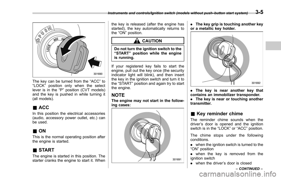
The key can be turned from the“ACC”to
“ LOCK ”position only when the select
lever is in the “P”position (CVT models)
and the key is pushed in while turning it
(all models).
& ACC
In this position the electrical accessories
(audio, accessory power outlet, etc.) can
be used.
&ON
This is the normal operating position after
the engine is started.
&START
The engine is started in this position. The
starter cranks the engine to start it. When the key is released (after the engine has
started), the key automatically returns to
the
“ON ”position.
CAUTION
Do not turn the ignition switch to the
“START ”position while the engine
is running.
If your registered key fails to start the
engine, pull out the key once (the security
indicator light will blink), and then insert
the key in the ignition switch and turn it to
the “START ”position and again try to start
the engine.
NOTE
The engine may not start in the follow-
ing cases:
. The key grip is touching another key
or a metallic key holder.
. The key is near another key that
contains an immobilizer transponder.
. The key is near or touching another
transmitter.
& Key reminder chime
The reminder chime sounds when the
driver ’s door is opened and the ignition
switch is in the “LOCK ”or “ACC ”position.
The chime stops under the following
conditions.
. when the ignition switch is turned to the
“ON ”position
. when the key is removed from the
ignition switch
. when the driver ’s door is closed
Instruments and controls/Ignition switch (models without push –button start system)
–CONTINUED –3-5
Page 157 of 634

Instruments and controls/Push–button ignition switch (models with push –button start system)
& Ignition switch light (if
equipped)
For easy access to the ignition switch in
the dark, the ignition switch light illumi-
nates when the driver ’s door is opened or
when the driver ’s door is unlocked using
the remote keyless entry transmitter.
The light remains illuminated for several
tens of seconds and then gradually turns
off under the following conditions.
. when the driver ’s door is closed
. when the doors are unlocked using the
remote keyless entry transmitter
The light turns off immediately under the
following conditions.
. when the ignition switch is turned to the
“ ON ”position
. when all doors and the rear gate are
locked using the remote keyless entry
transmitter
Push-button ignition switch
(models with push-button
start system)
& Safety precautions
Refer to “Safety precautions” F2-10.
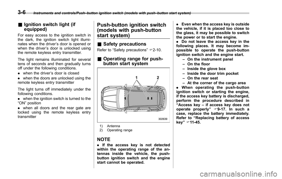
& Operating range for push-
button start system
1) Antenna
2) Operating range
NOTE
. If the access key is not detected
within the operating range of the an-
tennas inside the vehicle, the push-
button ignition switch and the engine
start cannot be operated. .
Even when the access key is outside
the vehicle, if it is placed too close to
the glass, it may be possible to switch
the power or to start the engine.
. Do not leave the access key in the
following places. It may become im-
possible to operate the push-button
ignition switch and the engine start.
–On the instrument panel
– On the floor
– Inside the glove box
– Inside the door trim pocket
– On the rear seat
– At the corner of the cargo area
. When operating the push-button
ignition switch or starting the engine,
if the access key battery is discharged,
perform the procedure described in
“ Access key –if access key does not
operate properly ”F9-17. In such a
case, replace the battery immediately.
Refer to “Replacing battery of access
key ”F 11-45.
3-6
Page 158 of 634

&Switching power status
1) Operation indicator
2) Push-button ignition switch
The power is switched every time the
push-button ignition switch is pressed.
1. Carry the access key, and sit in the
driver ’s seat.
2. Shift the select lever into the “P ”
position.
3. Press the push-button ignition switch
without depressing the brake pedal. Every
time the button is pressed, the power is
switched in the sequence of “OFF ”,
“ACC ”,“ON ”and “OFF ”. When the engine
is stopped and the push-button ignition
switch is in “ACC”or “ON ”, the operation
indicator on the push-button ignition
switch illuminates in orange.
Power status Indicator color Operation
OFF Turned off Power is turned
off.
ACC Orange The following
systems can be used:
audio and ac-
cessory power
outlet.
ON Orange
(while engine is stopped) All electrical
systems can be
used.
Turned off
(while engine is
running)
CAUTION
.When the push-button ignition
switch is left in “ON ”or “ACC ”
for a long time, it may result in
vehicle battery discharge.
. Do not spill drinks or other
liquids on the push-button igni-
tion switch. It may cause a mal-
function.
. Do not touch the push-button
ignition switch with a hand soiled
with oil or other contaminants. It
may cause a malfunction.
. If the push-button ignition switch does not operate smoothly, stop
the operation. Contact a
SUBARU dealer immediately.
. If the push-button ignition switch
does not illuminate even when
the instrument panel illumination
is turned on, have the vehicle
inspected at a SUBARU dealer.
. If the vehicle was left in the hot
sun for a long time, the surface of
the push-button ignition switch
may get hot. Be careful not to
burn yourself.
NOTE
. When operating the push-button
ignition switch, firmly press it all the
way.
. If the push-button ignition switch is
pressed quickly, the power may not
turn on or off.
. If the indicator light on the push-
button ignition switch flashes in green
when the push-button ignition switch is
pressed, steering is locked. When this
occurs, press the push-button ignition
switch while turning the steering wheel
left and right.
Instruments and controls/Push –button ignition switch (models with push –button start system)
–CONTINUED –3-7