2017 SUBARU FORESTER door lock
[x] Cancel search: door lockPage 139 of 634
Keys and doors/Windows
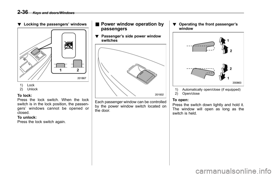
!Locking the passengers ’windows
1) Lock
2) Unlock
To lock:
Press the lock switch. When the lock
switch is in the lock position, the passen-
gers ’windows cannot be opened or
closed.
To unlock:
Press the lock switch again.
& Power window operation by
passengers
! Passenger ’s side power window
switches
Each passenger window can be controlled
by the power window switch located on
the door. !
Operating the front passenger ’s
window
1) Automatically open/close (if equipped)
2) Open/close
To open:
Press the switch down lightly and hold it.
The window will open as long as the
switch is held.
2-36
Page 140 of 634
NOTE
If you continue to hold the AUTO
switch in the down position after the
window has been fully opened, the
circuit breaker may activate for a short
time and the window may not operate.
Allow several seconds for the system
to reset without touching the switch,
and the window will begin to operate
normally on its own.
For some models, this switch is also
equipped with a one-touch auto down
feature that allows the window to be
opened fully without holding the switch.
Press the switch down until it clicks and
release it, and the window will fully open.
To stop the window halfway, pull the
switch up lightly.
To close:
Pull the switch up lightly and hold it. The
window will close as long as the switch is
held.
NOTE
If you continue to hold the AUTO
switch in the up position after the
window has fully closed, the circuit
breaker may open and the system may
not operate. After several seconds, the
window will be able to be opened by
holding the switch down until it is fullyopened. The AUTO function will not
operate. The window can be raised by
pulling up on the switch several times
until the window is fully closed.
To reset to normal operation, initialize
the power window to reactivate the
one-touch auto up/down function. Re-
fer to
“Initialization of power window ”
F 2-38.
For some models, this switch is also
equipped with a one-touch auto up feature
that allows the window to be closed fully
without holding the switch.
Press the switch up until it clicks and
release it, and the window will fully close.
To stop the window halfway, push the
switch down lightly.
NOTE
If the vehicle ’s battery is disconnected
due to situations such as battery or
fuse replacement, the one-touch auto
up/down function will be deactivated.
Initialize the power window to reacti-
vate the one-touch auto up/down func-
tion. Refer to “Initialization of power
window ”F 2-38.
! Anti-entrapment function
Refer to “Anti-entrapment function ”F 2-
35. !
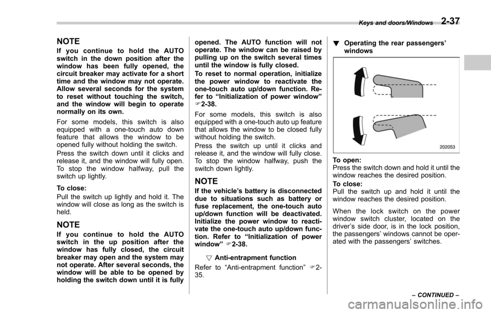
Operating the rear passengers ’
windows
To open:
Press the switch down and hold it until the
window reaches the desired position.
To close:
Pull the switch up and hold it until the
window reaches the desired position.
When the lock switch on the power
window switch cluster, located on the
driver ’s side door, is in the lock position,
the passengers’ windows cannot be oper-
ated with the passengers’ switches.
Keys and doors/Windows
–CONTINUED –2-37
Page 141 of 634
Keys and doors/Rear gate
&Initialization of power win-
dow
If the vehicle’ s battery is disconnected due
to situations such as battery or fuse
replacement, the following functions will
be deactivated.
. One-touch auto up/down function
. Anti-entrapment function
Initialize the power window using the
following procedure to reactivate these
functions.
1. Close the driver ’s door.
2. Turn the ignition switch to the “ON”
position.
3. Open the driver ’s side window halfway
by pushing down the power window
switch.
4. Pull up the power window switch and
close the window completely. Continue
pulling up the switch for approximately 1
second after the window is closed com-
pletely.
5. Open the driver ’s side window com-
pletely by fully pushing down the power
windows switch.
Rear gate
& Manual rear gate (if
equipped)
The rear gate can be locked and unlocked
using any of the following systems.
. Power door locking switch: Refer to
“Power door locking switches ”F 2-8.
. Keyless access with the push-button
start system (if equipped): Refer to “Key-
less access with push-button start system ”
F 2-9.
. Remote keyless entry system: Refer to
“Remote keyless entry system ”F 2-21.
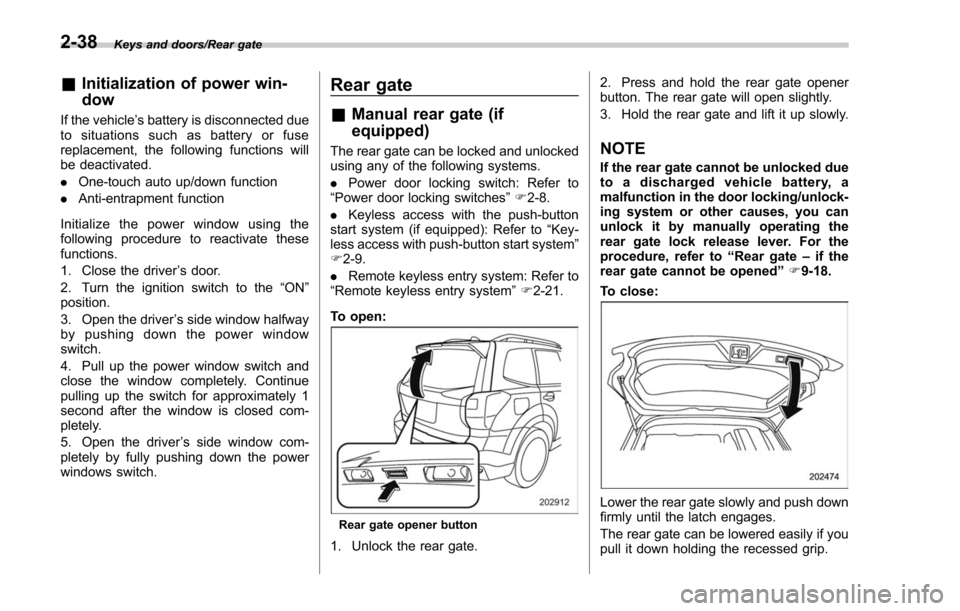
To open:
Rear gate opener button
1. Unlock the rear gate. 2. Press and hold the rear gate opener
button. The rear gate will open slightly.
3. Hold the rear gate and lift it up slowly.
NOTE
If the rear gate cannot be unlocked due
to a discharged vehicle battery, a
malfunction in the door locking/unlock-
ing system or other causes, you can
unlock it by manually operating the
rear gate lock release lever. For the
procedure, refer to
“Rear gate–if the
rear gate cannot be opened ”F 9-18.
To close:
Lower the rear gate slowly and push down
firmly until the latch engages.
The rear gate can be lowered easily if you
pull it down holding the recessed grip.
2-38
Page 143 of 634

Keys and doors/Rear gate
The power rear gate operates only when
all of the following conditions are satisfied.
.The vehicle is stopped completely.
. The outside temperature is within a
range from −22 8F to 1588 F (from−30 8Cto
70 8C).
. The ignition switch is in the “LOCK”/
“OFF ”or “ACC ”position. Or, the ignition
switch is in the “ON”position and the
parking brake is applied (MT models)/the
select lever is in the “P”position (CVT
models).
NOTE
. If the button is pressed repeatedly
while the power rear gate is operating,
the system may ignore the button
operation in order to avoid being
damaged. Do not press the button
unnecessarily.
. It is not possible to stop the rear
gate temporarily while opening be-
tween the completely closed position
and approximately 12 in (30 cm) open.
If you press one of the power rear gate
buttons briefly during this range, the
rear gate will be closed.
. If the vehicle starts to move while
the power rear gate is operating, the
system sounds a buzzer and closes the
rear gate automatically. At this time, if
the system detects jamming, it will deactivate the power rear gate and the
rear gate will not be closed. If this
occurs, close the rear gate via regular
procedures.
.
If you try to open the rear gate using
the power rear gate function immedi-
ately after closing the rear gate using
the power rear gate function, an elec-
tronic chirp will sound and the rear
gate will not open. Wait for a while
before trying to open the rear gate via
the power rear gate function. If you
wish to open it right away, it can be
opened manually. !
Operation by the button on the
instrument panelPower rear gate button
To open the rear gate:
Press and hold the power rear gate button
when the rear gate is closed. Then an
electronic chirp will sound twice and the
hazard warning flashers will flash twice.
The rear gate will open automatically.
To stop the rear gate midway:
Briefly press the power rear gate button
while the rear gate is being opened. Then
the hazard warning flashers will flash
twice. If the button is pressed again, the
rear gate will close. If the button is briefly
pressed while the gate is closed, the rear
gate can be opened. However, the rear
gate cannot be stopped again while it is
2-40
Page 146 of 634
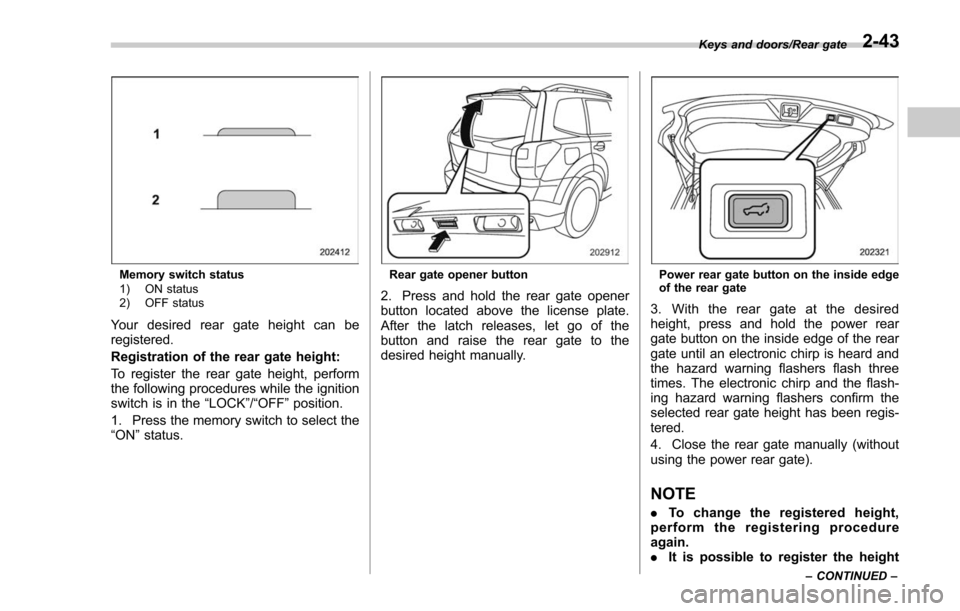
Memory switch status
1) ON status
2) OFF status
Your desired rear gate height can be
registered.
Registration of the rear gate height:
To register the rear gate height, perform
the following procedures while the ignition
switch is in the“LOCK”/“OFF ”position.
1. Press the memory switch to select the
“ON ”status.
Rear gate opener button
2. Press and hold the rear gate opener
button located above the license plate.
After the latch releases, let go of the
button and raise the rear gate to the
desired height manually.
Power rear gate button on the inside edge
of the rear gate
3. With the rear gate at the desired
height, press and hold the power rear
gate button on the inside edge of the rear
gate until an electronic chirp is heard and
the hazard warning flashers flash three
times. The electronic chirp and the flash-
ing hazard warning flashers confirm the
selected rear gate height has been regis-
tered.
4. Close the rear gate manually (without
using the power rear gate).
NOTE
. To change the registered height,
perform the registering procedure
again.
. It is possible to register the height
Keys and doors/Rear gate
–CONTINUED –2-43
Page 152 of 634

Ignition switch (models without push-button start system) ......................................... 3-4
LOCK.................................................................. 3-4
ACC.................................................................... 3-5
ON...................................................................... 3-5
START ................................................................ 3-5
Key reminder chime ............................................ 3-5
Ignition switch light (if equipped) ......................... 3-6
Push-button ignition switch (models with
push-button start system) ............................... 3-6
Safety precautions.............................................. 3-6
Operating range for push-button start system ...... 3-6
Switching power status ....................................... 3-7
When access key does not operate properly ........ 3-8
Hazard warning flasher....................................... 3-8
Meters and gauges. ............................................. 3-9
Combination meter illumination ........................... 3-9
Canceling the function for meter/gauge needle movement upon turning on the ignition
switch ............................................................... 3-9
Speedometer ...................................................... 3-10
Odometer ........................................................... 3-10
Double trip meter ............................................... 3-10
Tachometer ........................................................ 3-11
Fuel gauge ......................................................... 3-12
ECO gauge (if equipped) .................................... 3-12
Warning and indicator lights ............................. 3-13Seatbelt warning light and chime ........................ 3-14
SRS airbag system warning light ........................ 3-15
Front passenger ’s frontal airbag ON and OFF
indicators ......................................................... 3-16 CHECK ENGINE warning light/Malfunction
indicator light .................................................. 3-16
Coolant temperature low indicator light/Coolant temperature high warning light ......................... 3-17
Charge warning light .......................................... 3-18
Oil pressure warning light .................................. 3-18
Engine low oil level warning light ....................... 3-18
Windshield washer fluid warning light ................ 3-19
AT OIL TEMP warning light (CVT models) ........... 3-19
Low tire pressure warning light (U.S.-spec. models) ........................................................... 3-19
ABS warning light .............................................. 3-21
Brake system warning light ................................ 3-21
Low fuel warning light ....................................... 3-22
Hill start assist warning light/Hill start assist OFF indicator light .................................................. 3-23
Door open warning light .................................... 3-23
All-Wheel Drive warning light (CVT models) ... ..... 3-23
Power steering warning light .............................. 3-23
Vehicle Dynamics Control warning light/Vehicle Dynamics Control operation indicator light .. ..... 3-24
Vehicle Dynamics Control OFF indicator light ..... 3-25
Warning chimes and warning light of the keyless access with push-button start system (if
equipped) ........................................................ 3-25
Security indicator light ....................................... 3-30
SI-DRIVE indicator light (if equipped) .................. 3-31
Select lever/gear position indicator (CVT models) ........................................................... 3-31
Turn signal indicator lights ................................. 3-32
High beam indicator light ................................... 3-32
High beam assist indicator light (if equipped) ..... 3-32
Instruments and controls
3
Page 156 of 634
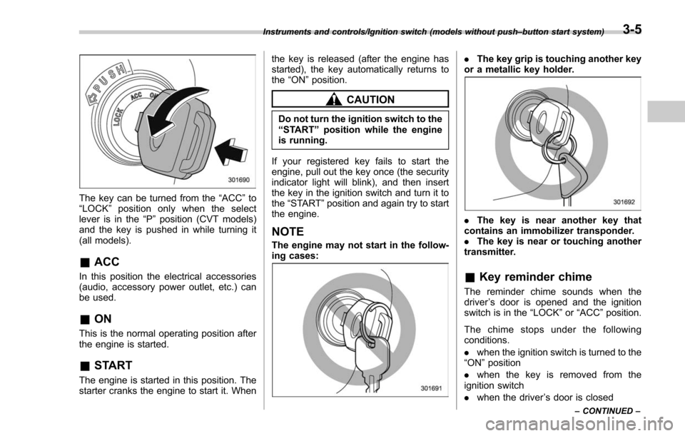
The key can be turned from the“ACC”to
“ LOCK ”position only when the select
lever is in the “P”position (CVT models)
and the key is pushed in while turning it
(all models).
& ACC
In this position the electrical accessories
(audio, accessory power outlet, etc.) can
be used.
&ON
This is the normal operating position after
the engine is started.
&START
The engine is started in this position. The
starter cranks the engine to start it. When the key is released (after the engine has
started), the key automatically returns to
the
“ON ”position.
CAUTION
Do not turn the ignition switch to the
“START ”position while the engine
is running.
If your registered key fails to start the
engine, pull out the key once (the security
indicator light will blink), and then insert
the key in the ignition switch and turn it to
the “START ”position and again try to start
the engine.
NOTE
The engine may not start in the follow-
ing cases:
. The key grip is touching another key
or a metallic key holder.
. The key is near another key that
contains an immobilizer transponder.
. The key is near or touching another
transmitter.
& Key reminder chime
The reminder chime sounds when the
driver ’s door is opened and the ignition
switch is in the “LOCK ”or “ACC ”position.
The chime stops under the following
conditions.
. when the ignition switch is turned to the
“ON ”position
. when the key is removed from the
ignition switch
. when the driver ’s door is closed
Instruments and controls/Ignition switch (models without push –button start system)
–CONTINUED –3-5
Page 157 of 634
Instruments and controls/Push–button ignition switch (models with push –button start system)
& Ignition switch light (if
equipped)
For easy access to the ignition switch in
the dark, the ignition switch light illumi-
nates when the driver ’s door is opened or
when the driver ’s door is unlocked using
the remote keyless entry transmitter.
The light remains illuminated for several
tens of seconds and then gradually turns
off under the following conditions.
. when the driver ’s door is closed
. when the doors are unlocked using the
remote keyless entry transmitter
The light turns off immediately under the
following conditions.
. when the ignition switch is turned to the
“ ON ”position
. when all doors and the rear gate are
locked using the remote keyless entry
transmitter
Push-button ignition switch
(models with push-button
start system)
& Safety precautions
Refer to “Safety precautions” F2-10.
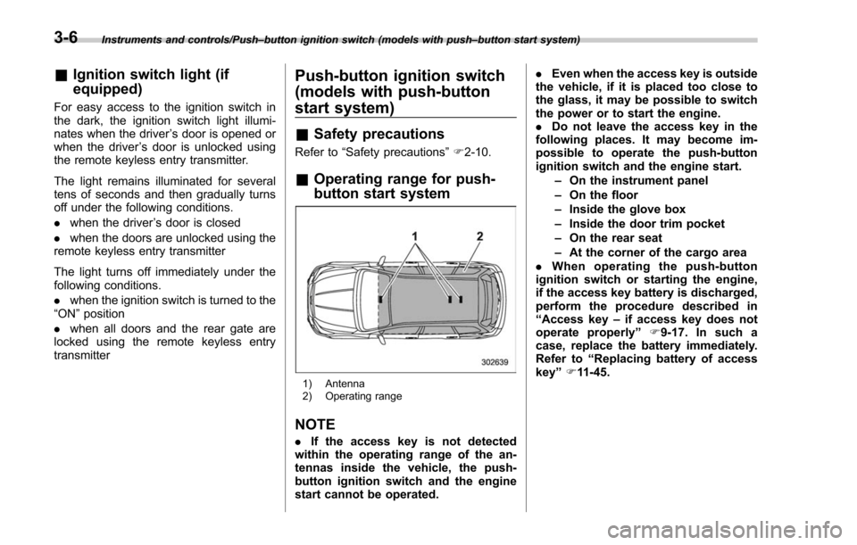
& Operating range for push-
button start system
1) Antenna
2) Operating range
NOTE
. If the access key is not detected
within the operating range of the an-
tennas inside the vehicle, the push-
button ignition switch and the engine
start cannot be operated. .
Even when the access key is outside
the vehicle, if it is placed too close to
the glass, it may be possible to switch
the power or to start the engine.
. Do not leave the access key in the
following places. It may become im-
possible to operate the push-button
ignition switch and the engine start.
–On the instrument panel
– On the floor
– Inside the glove box
– Inside the door trim pocket
– On the rear seat
– At the corner of the cargo area
. When operating the push-button
ignition switch or starting the engine,
if the access key battery is discharged,
perform the procedure described in
“ Access key –if access key does not
operate properly ”F9-17. In such a
case, replace the battery immediately.
Refer to “Replacing battery of access
key ”F 11-45.
3-6