2017 SUBARU FORESTER display
[x] Cancel search: displayPage 197 of 634
Instruments and controls/Multi function display
&Ending screen
If the ignition switch is turned to the
“LOCK”/ “OFF ”position, one of the follow-
ing screens will be displayed as the
ending screen before the screen turns off.
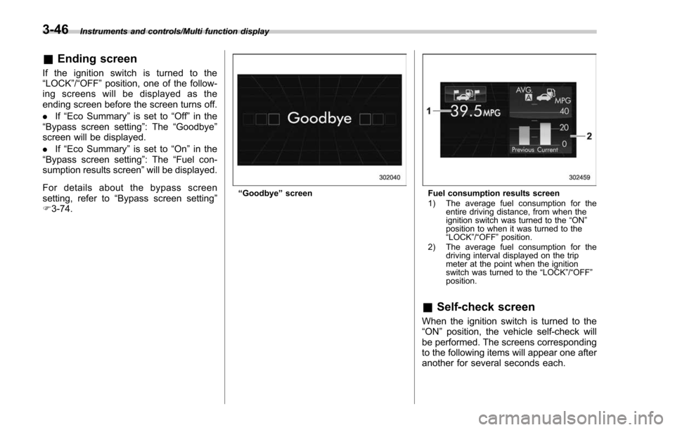
. If“Eco Summary ”is set to “Off ”in the
“Bypass screen setting ”: The“Goodbye ”
screen will be displayed.
. If“Eco Summary ”is set to “On”in the
“ Bypass screen setting ”: The “Fuel con-
sumption results screen” will be displayed.
For details about the bypass screen
setting, refer to “Bypass screen setting ”
F 3-74.
“Goodbye ”screenFuel consumption results screen
1) The average fuel consumption for the
entire driving distance, from when the
ignition switch was turned to the “ON ”
position to when it was turned to the
“ LOCK ”/“ OFF ”position.
2) The average fuel consumption for the driving interval displayed on the trip
meter at the point when the ignition
switch was turned to the “LOCK ”/“ OFF ”
position.
& Self-check screen
When the ignition switch is turned to the
“ON ”position, the vehicle self-check will
be performed. The screens corresponding
to the following items will appear one after
another for several seconds each.
3-46
Page 198 of 634

Type A combination meter
1) Engine oil: Checks the interval of engineoil replacement.
2) Oil filter: Checks the interval of oil filter replacement.
3) Tires: Checks the interval of tire rotation.
4) Inspection and maintenance: Checks the interval of inspection and maintenance.Type B combination meter
1) Windshield washer fluid: Checks thelevel of windshield washer fluid.
2) Brake fluid: Checks the level of brake fluid.
3) Engine oil: Checks the interval of engine oil replacement.
4) Oil filter: Checks the interval of oil filter replacement.
5) Tires: Checks the interval of tire rotation.
6) Inspection and maintenance: Checks the interval of inspection and maintenance.
When the checks are performed, the color
of the icon corresponding to the checked
item will turn green.
If there is no warning message, the self-
check will complete without notification.
Example of notification
If there is a warning message or a
maintenance notification, the color of the
icon corresponding to the item will turn
yellow and the warning message or the
maintenance notification will be displayed.
Take the appropriate actions based on the
messages indicated.
NOTE
.The self-check screen can be set to
on or off. For details, refer to “On/Off
setting ”F 3-77.
. After performing the maintenance,
change the setting of the correspond-
ing maintenance item. For details, refer
to “Maintenance settings ”F 3-76.
. The maintenance notification screen
will be displayed under either of the
Instruments and controls/Multi function display
–CONTINUED –3-47
Page 199 of 634
Instruments and controls/Multi function display
following conditions.–The period of time remaining
until the registered notification date
is 15 days or less.
– The total driving distance remain-
ing until the registered notification
distance is approximately 311 miles
(500 km) or less.
. The maintenance notification screen
will be displayed until either of the
following conditions is satisfied.
–The period of time passed after
the registered notification date is 15
days or more.
– The total distance driven after the
registered notification distance is
approximately 311 miles (500 km) or
more.& Interruption screen
Warning information (display example)
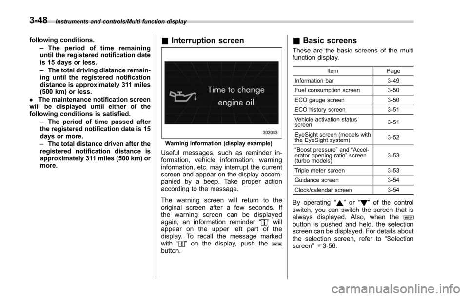
Useful messages, such as reminder in-
formation, vehicle information, warning
information, etc. may interrupt the current
screen and appear on the display accom-
panied by a beep. Take proper action
according to the message.
The warning screen will return to the
original screen after a few seconds. If
the warning screen can be displayed
again, an information reminder “
”will
appear on the upper left part of the
display. To recall the message marked
with “
”on the display, push thebutton.
& Basic screens
These are the basic screens of the multi
function display.
Item Page
Information bar 3-49
Fuel consumption screen 3-50
ECO gauge screen 3-50
ECO history screen 3-51
Vehicle activation status
screen 3-51
EyeSight screen (models with
the EyeSight system) 3-52
“ Boost pressure ”and “Accel-
erator opening ratio ”screen
(turbo models) 3-53
Triple meter screen 3-53
Guidance screen 3-54
Clock/calendar screen 3-54
By operating
“”or “”of the control
switch, you can switch the screen that is
always displayed. Also, when the
button is pushed and held, the selection
screen can be displayed. For details about
the selection screen, refer to “Selection
screen” F3-56.
3-48
Page 200 of 634

!Information bar
1) Information bar
2) Outside temperature indicator
3) Information reminder (models with type A
combination meter)
4) Top display
5) Clock
While the ignition switch is in the “ACC ”or
“ON ”position, the outside temperature
indicator, clock, etc. will be shown on the
information bar.
!Outside temperature indicator
This displays the outside temperature
between −408 F( −408 C) and 122 8F
(50 8C).
Icy road surface warning screen
When the outside temperature becomes
37 8F(3 8C) or less, the icy road surface
warning screen interrupts to inform the
driver that the road surface may be frozen.
NOTE
. The outside temperature indicator
shows the temperature around the
sensor. Therefore, the temperature in-
dication may differ from the actual
outside air temperature.
. The icy road surface warning screen
should be treated only as a guide. Be
sure to check the condition of the road
surface before driving.
. Once the icy road surface warning
screen is displayed, it will not be
displayed again unless the ignition switch is turned to the
“ACC ”or “ON ”
position after it has been turned to
“ LOCK ”/“ OFF ”position.
! Information reminder
The screen returns to the original screen
several seconds after the interruption
screen has been displayed. If the inter-
ruption screen can be displayed once
more even after the original screen has
appeared, an information reminder should
be displayed. For details about the inter-
ruption screen, refer to “Interruption
screen” F3-48.
! Top display
One of the following items can be dis-
played on the top display.
. Average fuel consumption correspond-
ing to the driving distance of each trip
meter
. Current fuel consumption (This may
not be displayed when driving at a low
speed.)
. Driving range on remaining fuel
For details about the setting of the top
display, refer to “Top display setting ”F 3-
68.
Instruments and controls/Multi function display
–CONTINUED –3-49
Page 201 of 634
Instruments and controls/Multi function display
NOTE
The driving range on the remaining fuel
is calculated using the average fuel
consumption of the last 19 miles (30
km) driven. This value may be different
from the values calculated using the
average fuel consumption correspond-
ing to the driving distance of each trip
meter or the current fuel consumption.!Clock
The clock can be displayed in either 12-
hour display or 24-hour display. For details
about the setting, refer to “Current date
and time setting ”F 3-59.
NOTE
If the vehicle battery is disconnected,
the clock shown in the information bar
will be reset. Set the time again after
the vehicle battery is connected. For
details about the setting, refer to “To p
display setting ”F 3-68. !
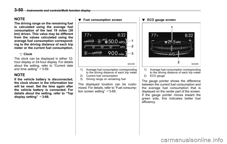
Fuel consumption screen
1) Average fuel consumption corresponding
to the driving distance of each trip meter
2) Current fuel consumption
3) Driving range on remaining fuel
The displayed location can be custo-
mized. For details, refer to “Fuel consump-
tion screen setting ”F 3-69. !
ECO gauge screen
1) Average fuel consumption corresponding
to the driving distance of each trip meter
2) ECO gauge
The gauge pointer shows the difference
between the current fuel consumption and
the average fuel consumption that is
displayed on the center part of the screen.
If the gauge pointer moves toward the
green side, this indicates better fuel
efficiency.
3-50
Page 202 of 634
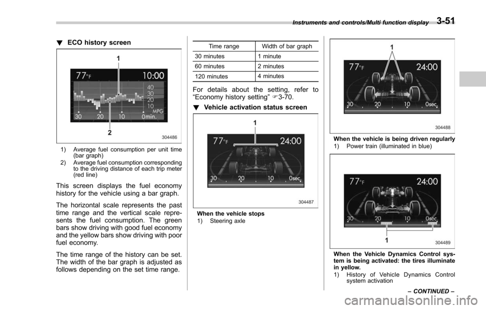
!ECO history screen
1) Average fuel consumption per unit time
(bar graph)
2) Average fuel consumption corresponding to the driving distance of each trip meter
(red line)
This screen displays the fuel economy
history for the vehicle using a bar graph.
The horizontal scale represents the past
time range and the vertical scale repre-
sents the fuel consumption. The green
bars show driving with good fuel economy
and the yellow bars show driving with poor
fuel economy.
The time range of the history can be set.
The width of the bar graph is adjusted as
follows depending on the set time range.
Time range Width of bar graph
30 minutes 1 minute
60 minutes 2 minutes
120 minutes 4 minutes
For details about the setting, refer to
“Economy history setting
”F 3-70.
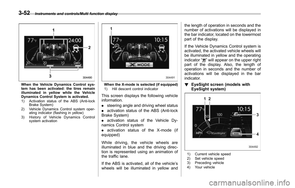
! Vehicle activation status screen
When the vehicle stops
1) Steering axle
When the vehicle is being driven regularly
1) Power train (illuminated in blue)
When the Vehicle Dynamics Control sys-
tem is being activated: the tires illuminate
in yellow.
1) History of Vehicle Dynamics Control
system activation
Instruments and controls/Multi function display
–CONTINUED –
3-51
Page 203 of 634
Instruments and controls/Multi function display
When the Vehicle Dynamics Control sys-
tem has been activated: the tires remain
illuminated in yellow while the Vehicle
Dynamics Control System is activated.
1) Activation status of the ABS (Anti-lockBrake System)
2) Vehicle Dynamics Control system oper- ating indicator (flashing in yellow)
3) History of Vehicle Dynamics Control system activationWhen the X-mode is selected (if equipped)
1) Hill descent control indicator
This screen displays the following vehicle
information.
.steering angle and driving wheel status
. activation status of the ABS (Anti-lock
Brake System)
. activation status of the Vehicle Dy-
namics Control system
. activation status of the X-mode (if
equipped)
While driving, the vehicle wheels are
illuminated in blue and the driving direc-
tion is represented using an animation of
the traffic lane.
If the ABS is activated, all of the vehicle’ s
wheels will be illuminated in yellow and the length of operation in seconds and the
number of activations will be displayed in
the bar indicator, located on the lowermost
part of the display.
If the Vehicle Dynamics Control system is
activated, the activated vehicle wheels will
be illuminated in yellow and the operating
indicator
“
”will appear on the upper right
part of the display. Also, the length of
operation in seconds and the number of
activations will be displayed in the bar
indicator.
! EyeSight screen (models with
EyeSight system)
1) Current vehicle speed
2) Set vehicle speed
3) Preceding vehicle
4) Your vehicle
3-52
Page 204 of 634
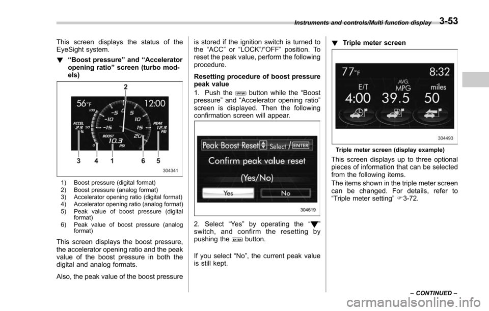
This screen displays the status of the
EyeSight system.
!“Boost pressure ”and “Accelerator
opening ratio ”screen (turbo mod-
els)
1) Boost pressure (digital format)
2) Boost pressure (analog format)
3) Accelerator opening ratio (digital format)
4) Accelerator opening ratio (analog format)
5) Peak value of boost pressure (digital format)
6) Peak value of boost pressure (analog format)
This screen displays the boost pressure,
the accelerator opening ratio and the peak
value of the boost pressure in both the
digital and analog formats.
Also, the peak value of the boost pressure is stored if the ignition switch is turned to
the
“ACC ”or “LOCK ”/“OFF ”position. To
reset the peak value, perform the following
procedure.
Resetting procedure of boost pressure
peak value
1. Push the
button while the “Boost
pressure ”and “Accelerator opening ratio ”
screen is displayed. Then the following
confirmation screen will appear.
2. Select “Ye s ”by operating the “”
switch, and confirm the resetting by
pushing the
button.
If you select “No”, the current peak value
is still kept. !
Triple meter screen
Triple meter screen (display example)
This screen displays up to three optional
pieces of information that can be selected
from the following items.
The items shown in the triple meter screen
can be changed. For details, refer to
“Triple meter setting ”F 3-72.
Instruments and controls/Multi function display
–CONTINUED –3-53