2017 SUBARU FORESTER height
[x] Cancel search: heightPage 464 of 634

operation and the BSD/RCTA warning
indicator will disappear. However, if the
BSD/RCTA warning indicator has ap-
peared for a prolonged time, have the
system inspected at a SUBARU dealer
as soon as possible.
.The detectability of the radar sen-
sors is restricted. The BSD/RCTA de-
tection may be impaired and the sys-
tem may not operate properly under the
following conditions.
–When the rear bumper around
the radar sensors is distorted
– When ice, snow or mud adheres
to the rear bumper surface around
the radar sensors
– When stickers, etc. are affixed on
the areas of the radar sensors on
the rear bumper
– During adverse weather condi-
tions such as rain, snow or fog
– When driving on wet roads such
as snow-covered roads and
through puddles
. The radar sensors may not detect or
may have difficulty detecting the fol-
lowing.
–Small motorcycles, bicycles, pe-
destrians, stationary objects on the
road or road side, etc.
– Vehicles with body shapes that
the radar may not reflect (vehicles with a low body height such as
sports cars or a trailer with no
cargo)
–
Vehicles that are not approach-
ing your vehicle even though they
are in the detection area (either on a
neighboring lane to the rear or
beside your vehicle when rever-
sing) (The system determines the
presence of approaching vehicles
based on data detected by the radar
sensors.)
– Vehicles traveling at significantly
different speeds
– Vehicles driving in parallel at
almost the same speed as your
vehicle for a prolonged time
– Oncoming vehicles
– Vehicles in a lane beyond the
neighboring lane
– Vehicles travelling at a signifi-
cantly lower speed that you are
trying to overtake
. On a road with extremely narrow
lanes, the system may detect vehicles
driving in a lane next to the neighbor-
ing lane.& BSD/RCTA approach indica-
tor light/warning buzzer
While the BSD/RCTA is active, the follow-
ing item(s) will operate to alert the driver.
. The BSD/RCTA approach indicator
light (when there are vehicles in the
neighboring lanes)
. The BSD/RCTA approach indicator
light and warning buzzer (when a vehicle
is approaching from the left or right side
while reversing)
! BSD/RCTA approach indicator light
BSD/RCTA approach indicator light
It is mounted in each side of the outside
mirrors and will illuminate when a vehicle
approaching from behind is detected. If an
indicator light is illuminated and the turn
Starting and operating/BSD/RCTA
–CONTINUED –7-61
Page 465 of 634

Starting and operating/BSD/RCTA
signal lever is operated toward the side in
which this light turned on, the indicator
light flashes to warn the driver of dangers.
When reversing the vehicle, the indicator
light flashes when the system detects a
vehicle approaching from either side.! BSD/RCTA approach indicator
light dimming function
When the headlights are turned on, the
brightness of the BSD/RCTA approach
indicator light will be reduced.
NOTE
. When affected by direct sunlight,
you may have difficulty recognizing
the BSD/RCTA approach indicator light.
. When affected by the headlight
beams from the vehicles behind, you
may have difficulty recognizing the
BSD/RCTA approach indicator light.
. While the illumination brightness
control dial is in the fully upward
position, even if the headlights are
turned on, the brightness of the BSD/
RCTA approach indicator light will not
be reduced. For details about the
illumination brightness control dial,
refer to “Illumination brightness con-
trol” F3-101. !
BSD/RCTA approach warning buz-
zer (only when reversing)
A warning buzzer sounds along with
flashing of the BSD/RCTA approach in-
dicator light to warn the driver of dangers.
The setting of the warning buzzer volume
can be changed by operating the multi
information display of the combination
meter. For details, refer to “BSD/RCTA”
F 3-43.
! Safety tips regarding the BSD/RCTA
approach indicator light/warning
buzzer
. In the following cases, operation of the
BSD/RCTA approach indicator light and
the warning buzzer may be delayed or the
system may fail to issue these warnings.
–Whenavehiclemovestothe
neighboring lane from a lane next to
the neighboring lane
– When driving on a steep incline or
on repeated sharp uphill and downhill
grades
– When going beyond a pass
– When both your vehicle and a
vehicle driving on a neighboring lane
are driving on the far side of each lane.
– When several narrowly-spaced ve-
hicles are approaching in a row
– In low radius bends (tight bends or when making turns at an intersection)
–
When there is a difference in height
between your lane and the neighbor-
ing lane
– Immediately after the BSD/RCTA is
activated by pressing the BSD/RCTA
OFF switch
– Immediately after the shift lever/
select lever is shifted to the “R ”
position
– When extremely heavy cargo is
loaded in the trunk or cargo area
. During reversing, operation of the BSD/
RCTA approach indicator light and the
warning buzzer may be delayed or the
system may fail to issue these warnings
under the following conditions.
–When backing out of an angled
parking space
– When a large-sized vehicle is
parked next to your vehicle (That
vehicle prevents the propagation of
radar waves.)
– When reversing on sloped roads
– When reversing at a high speed
7-62
Page 498 of 634

while driving.
!Tongue load
Tongue load
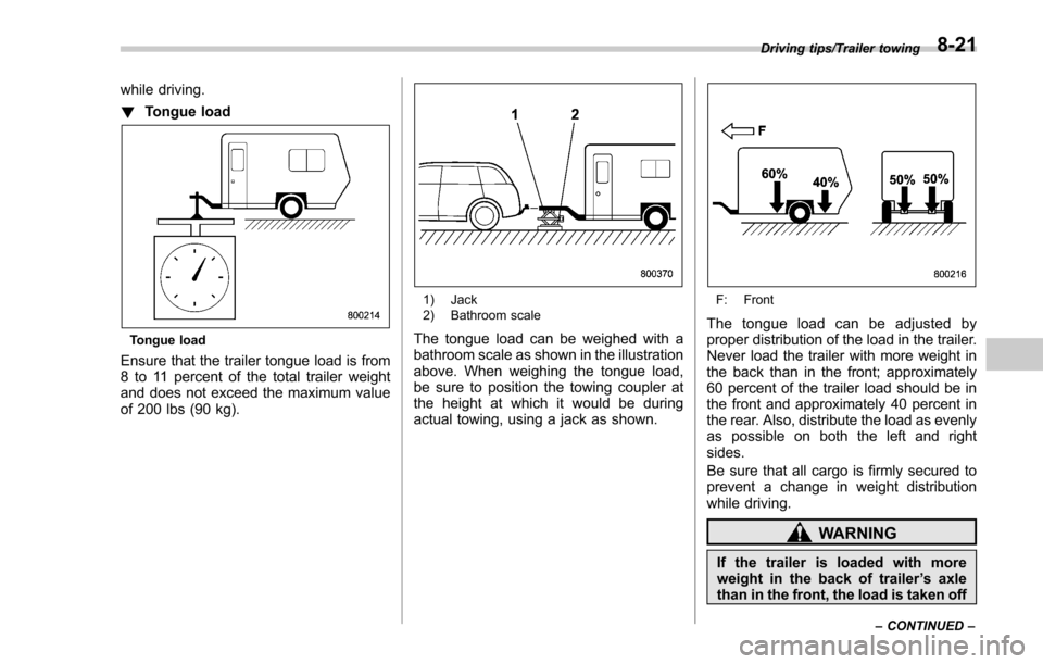
Ensure that the trailer tongue load is from
8 to 11 percent of the total trailer weight
and does not exceed the maximum value
of 200 lbs (90 kg).
1) Jack
2) Bathroom scale
The tongue load can be weighed with a
bathroom scale as shown in the illustration
above. When weighing the tongue load,
be sure to position the towing coupler at
the height at which it would be during
actual towing, using a jack as shown.
F: Front
The tongue load can be adjusted by
proper distribution of the load in the trailer.
Never load the trailer with more weight in
the back than in the front; approximately
60 percent of the trailer load should be in
the front and approximately 40 percent in
the rear. Also, distribute the load as evenly
as possible on both the left and right
sides.
Be sure that all cargo is firmly secured to
prevent a change in weight distribution
while driving.
WARNING
If the trailer is loaded with more
weight in the back of trailer ’s axle
than in the front, the load is taken off
Driving tips/Trailer towing
–CONTINUED –8-21
Page 538 of 634

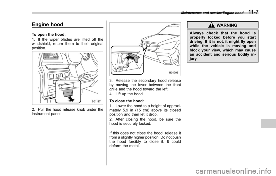
Engine hood
To open the hood:
1. If the wiper blades are lifted off the
windshield, return them to their original
position.
2. Pull the hood release knob under the
instrument panel.
3. Release the secondary hood release
by moving the lever between the front
grille and the hood toward the left.
4. Lift up the hood.
To close the hood:
1. Lower the hood to a height of approxi-
mately 5.9 in (15 cm) above its closed
position and then let it drop.
2. After closing the hood, be sure the
hood is securely locked.
If this does not close the hood, release it
from a slightly higher position. Do not push
the hood forcibly to close it. It could
deform the metal.
WARNING
Always check that the hood is
properly locked before you start
driving. If it is not, it might fly open
while the vehicle is moving and
block your view, which may cause
an accident and serious bodily in-
jury.
Maintenance and service/Engine hood11-7
Page 551 of 634

Maintenance and service/Brake booster
Brake booster
If the brake booster does not operate as
described in the following, have it checked
by your SUBARU dealer.
1. With the engine off, depress the brake
pedal several times, applying the same
pedal force each time. The distance the
pedal travels should not vary.
2. With the brake pedal depressed, start
the engine. The pedal should move
slightly down to the floor.
3. With the brake pedal depressed, stop
the engine and keep the pedal depressed
for 30 seconds. The pedal height should
not change.
4. Start the engine again and run for
approximately one minute then turn it off.
Depress the brake pedal several times to
check the brake booster. The brake
booster operates properly if the pedal
stroke decreases with each depression.
Brake pedal
Check the brake pedal free play and
reserve distance according to the main-
tenance schedule in the“Warranty and
Maintenance Booklet ”.
&Checking the brake pedal
free play
1) 0.02 - 0.11 in (0.5 - 2.7 mm)
Stop the engine and firmly depress the
brake pedal several times. Lightly pull the
brake pedal up with one finger to check
the free play with a force of less than 2 lbf
(10 N, 1 kgf).
If the free play is not within proper
specification, contact your SUBARU deal-
er.
&Checking the brake pedal
reserve distance
1) More than 2.56 in (65 mm)
Depress the pedal with a force of approxi-
mately 66 lbf (294 N, 30 kgf) and measure
the distance between the upper surface of
the pedal pad and the floor.
When the measurement is smaller than
the specification, or when the pedal does
not operate smoothly, contact with your
SUBARU dealer.
11-20
Page 581 of 634

Specifications/Specifications
Specifications
These specifications are subject to change without notice.
&Dimensions
in (mm)
Item Non-turbo models Turbo models
Overall length 181.5 (4,610) 180.9 (4,595)
Overall width 70.7 (1,795)
Overall height 68.3 (1,735)*
2
67.7 (1,720)*3
Wheel base 103.9 (2,640)
Tread Front 60.8 (1,545)
Rear 61.2 (1,555)
Ground clearance*
18.7 (220)
*1: Measured with vehicle empty
*2: Models with roof rails
*3: Models without roof rails
12-2
Page 601 of 634

Consumer information and Reporting safety defects/For U.S.A.
For U.S.A.
The following information has been
compiled according to Code of
Federal Regulations“Title 49, Part
575 ”.
Tire information
& Tire labeling
Many markings (e.g. Tire size, Tire
Identification Number or TIN) are
placed on the sidewall of a tire by
tire manufacturers. These markings
can provide you with useful infor-
mation on the tire.
! Tire size
Your vehicle comes equipped with
P-Metric tire size. It is important to
understand the sizing system in
selecting the proper tire for your
vehicles. Here is a brief review of
the tire sizing system with a break-
down of its individual elements.
!P Metric
With the P-Metric system, Section
Width is measured in millimeters.
To convert millimeters into inches,
divide by 25.4. The Aspect Ratio
(Section Height divided by Section
Width) helps provide more dimen-
sional information about the tire
size.
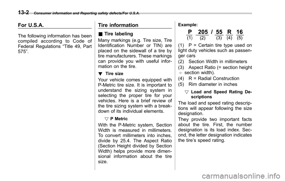
Example:
(1) P = Certain tire type used on
light duty vehicles such as passen-
ger cars
(2) Section Width in millimeters
(3) Aspect Ratio (= section height
7 section width).
(4) R = Radial Construction
(5) Rim diameter in inches
! Load and Speed Rating De-
scriptions
The load and speed rating descrip-
tions will appear following the size
designation.
They provide two important facts
about the tire. First, the number
designation is its load index. Sec-
ond, the letter designation indicates
the tire’ s speed rating.
13-2
Page 620 of 634

Warning................................................................ 3-22
Emergency Locking Retractor (ELR) ............................. 1-17
Engine
Compartment overview ........................................... 11-8
Coolant ........................................................ 11-13, 12-9
Exhaust gas (carbon monoxide) ............................. 5, 8-2
Hood .................................................................... 11-7
Low oil level warning light ....................................... 3-18
Oil............................................................... 11-10, 12-4
Overheating .......................................................... 9-12
Starting & stopping ........................................... 7-9, 7-12
Event data recorder ......................................................... 9
Exterior care .............................................................. 10-2
F
Flat tires ..................................................................... 9-5
Floor mat .................................................................. 6-12
Fluid level Brake .................................................................. 11-18
Clutch .................................................................. 11-19
Continuously variable transmission (CVT) ................ 11-17
Fog light ................................................................. 3-102
Bulb .......................................................... 11-42, 12-16
Indicator light ......................................................... 3-33
Switch ................................................................ 3-102
Front Differential gear oil ........................................ 11-17, 12-7
Seatbelt pretensioners ............................................ 1-25
Side marker light ................................................... 11-41
Turn signal/Parking and front side marker light ......... 11-41
Front fog light ................................................. 3- 102, 11-42Bulb
.......................................................... 11-42, 12-16
Indicator light ......................................................... 3-33
Switch ................................................................. 3-102
Front seats ................................................................. 1-2
Forward and backward adjustment ............................ 1-4
Head restraint adjustment ......................................... 1-8
Memory function ...................................................... 1-5
Power seat ............................................................. 1-5
Reclining ................................................................ 1-4
Seat height adjustment (driver ’s seat) ........................ 1-4
Front side marker ..................................................... 11-41
Front turn signal/Parking and front side marker ............ 11-41
Fuel ........................................................................\
... 7-3
Consumption indicator ............................ 3-34, 3-41, 3-48
Economy hints ........................................................ 8-2
Filler lid and cap ...................................................... 7-5
Gauge ................................................................... 3-12
Requirements ................................................. 7-3, 12-3
Fuses ..................................................................... 11-37
Fuses and circuits .................................................... 12-12
G
GAWR (Gross Axle Weight Rating) ............................... 8-14
Glove box ...................................................................
6-6
GVWR (Gross Vehicle Weight Rating) ........................... 8-14
H
Hands-free phone system ............................................ 5-70
Hazard warning flasher .......................................... 3-8, 9-2
Head restraint adjustment Front seat ............................................................... 1-8
Index14-5