2017 SUBARU FORESTER change time
[x] Cancel search: change timePage 146 of 634
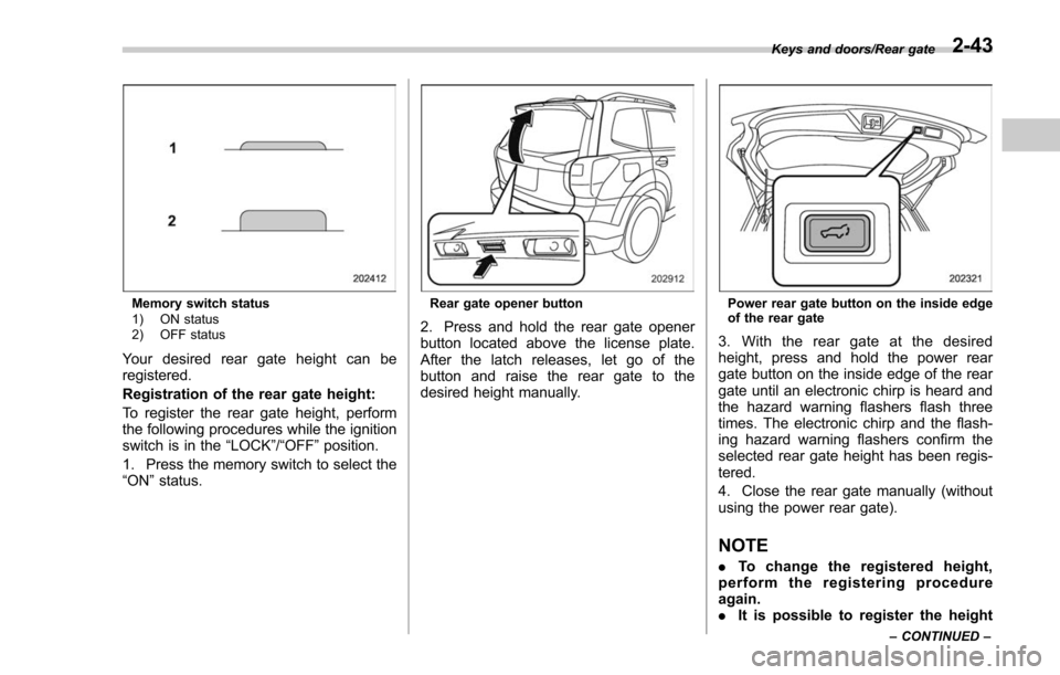
Memory switch status
1) ON status
2) OFF status
Your desired rear gate height can be
registered.
Registration of the rear gate height:
To register the rear gate height, perform
the following procedures while the ignition
switch is in the“LOCK”/“OFF ”position.
1. Press the memory switch to select the
“ON ”status.
Rear gate opener button
2. Press and hold the rear gate opener
button located above the license plate.
After the latch releases, let go of the
button and raise the rear gate to the
desired height manually.
Power rear gate button on the inside edge
of the rear gate
3. With the rear gate at the desired
height, press and hold the power rear
gate button on the inside edge of the rear
gate until an electronic chirp is heard and
the hazard warning flashers flash three
times. The electronic chirp and the flash-
ing hazard warning flashers confirm the
selected rear gate height has been regis-
tered.
4. Close the rear gate manually (without
using the power rear gate).
NOTE
. To change the registered height,
perform the registering procedure
again.
. It is possible to register the height
Keys and doors/Rear gate
–CONTINUED –2-43
Page 153 of 634

Instruments and controls
Cruise control indicator light (if equipped).......... 3-32
Cruise control set indicator light (if equipped) ......................................................... 3-32
Automatic headlight beam leveler warning light (if equipped) ......................................................... 3-32
Steering Responsive Headlight warning light/ Steering Responsive Headlight OFF indicator
light (if equipped) ............................................. 3-33
Front fog light indicator light (if equipped) .......... 3-33
Headlight indicator light (if equipped) ................. 3-33
X-mode indicator light (if equipped) .................... 3-33
Hill descent control indicator light (if equipped) ......................................................... 3-33
Steering responsive fog lights warning indicator/ Steering responsive fog lights OFF indicator (if
equipped) ......................................................... 3-33
BSD/RCTA warning indicator (if equipped) .......... 3-33
BSD/RCTA OFF indicator (if equipped) ................ 3-34
RAB warning light (if equipped) .......................... 3-34
RAB OFF indicator light (if equipped) .................. 3-34
Information display (Mexico-spec. models) ...... 3-34Outside temperature indicator............................ 3-34
Driving information display ................................. 3-35
Clock ................................................................. 3-38
Multi information display (models with type
B combination meter) ..................................... 3-39
Basic operation.................................................. 3-40
Welcome screen and Good-bye screen ............... 3-40
Warning screen .................................................. 3-41
Basic screens .................................................... 3-41
Menu screens .................................................... 3-42
Multi function display (if equipped) .................. 3-44Basic operation................................................. 3-45
Welcome screen ................................................ 3-45
Ending screen ................................................... 3-46
Self-check screen .............................................. 3-46
Interruption screen ............................................ 3-48
Basic screens .................................................... 3-48
Selection screen ................................................ 3-56
Date and time settings ....................................... 3-59
Image quality and volume settings ..................... 3-66
Screen settings. ................................................. 3-68
Maintenance settings ......................................... 3-76
Driving history registration ................................. 3-79
Car settings ....................................................... 3-80
Initialize ............................................................. 3-90
Light control switch ........................................... 3-93Headlights......................................................... 3-93
High/low beam change (dimmer) ... ..................... 3-95
Headlight flasher ............................................... 3-98
Daytime running light system ............................. 3-98
Steering Responsive Headlight (SRH) (if
equipped) ........................................................ 3-99
SRH OFF switch ................................................ 3-99
Turn signal lever .............................................. 3-100One-touch lane changer ................................... 3-101
Illumination brightness control ....................... 3-101
Headlight beam leveler (if equipped) ............. 3-102
Automatic headlight beam leveler (models with
LED headlights) ............................................. 3-102
Page 160 of 634
Meters and gauges
NOTE
Some of the meters and gauges on the
combination meter use liquid-crystal
displays. You will find their indications
hard to see if you wear polarized
glasses.
&Combination meter illumina-
tion
When the ignition switch is turned to the
“ON ”position, various parts of the combi-
nation meter will illuminate in the following
sequence.
1. Warning lights, indicator lights, meter
needles, gauge needles and liquid crystal
display illuminate.
2. Meter and gauge indications each
show MAX position.
3. Meter and gauge indications each
show MIN position.
4. Regular illumination (for driving) be-
gins.
& Canceling the function for
meter/gauge needle move-
ment upon turning on the
ignition switch
It is possible to activate or deactivate the
movement of the meter needles and
gauge needles that takes place when the
ignition switch is turned to the “ON ”
position. To change the setting, perform
the following procedure.
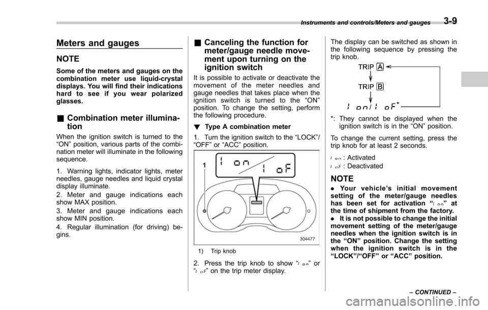
! Type A combination meter
1. Turn the ignition switch to the “LOCK”/
“OFF ”or “ACC ”position.
1) Trip knob
2. Press the trip knob to show “”or
“” on the trip meter display. The display can be switched as shown in
the following sequence by pressing the
trip knob.
*: They cannot be displayed when the
ignition switch is in the “ON ”position.
To change the current setting, press the
trip knob for at least 2 seconds.
: Activated
: Deactivated
NOTE
. Your vehicle’ s initial movement
setting of the meter/gauge needles
has been set for activation “
”at
the time of shipment from the factory.
. It is not possible to change the initial
movement setting of the meter/gauge
needles when the ignition switch is in
the “ON ”position. Change the setting
when the ignition switch is in the
“ LOCK ”/“ OFF ”or “ACC ”position.
Instruments and controls/Meters and gauges
–CONTINUED –3-9
Page 163 of 634
Instruments and controls/Meters and gauges
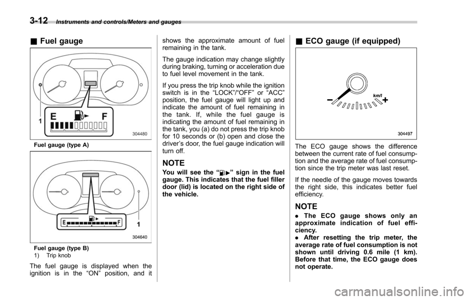
&Fuel gauge
Fuel gauge (type A)
Fuel gauge (type B)
1) Trip knob
The fuel gauge is displayed when the
ignition is in the “ON”position, and it shows the approximate amount of fuel
remaining in the tank.
The gauge indication may change slightly
during braking, turning or acceleration due
to fuel level movement in the tank.
If you press the trip knob while the ignition
switch is in the
“LOCK”/ “OFF”or “ACC ”
position, the fuel gauge will light up and
indicate the amount of fuel remaining in
the tank. If, while the fuel gauge is
indicating the amount of fuel remaining in
the tank, you (a) do not press the trip knob
for 10 seconds or (b) open and close the
driver ’s door, the fuel gauge indication will
turn off.
NOTE
You will see the “”sign in the fuel
gauge. This indicates that the fuel filler
door (lid) is located on the right side of
the vehicle.
& ECO gauge (if equipped)
The ECO gauge shows the difference
between the current rate of fuel consump-
tion and the average rate of fuel consump-
tion since the trip meter was last reset.
If the needle of the gauge moves towards
the right side, this indicates better fuel
efficiency.
NOTE
. The ECO gauge shows only an
approximate indication of fuel effi-
ciency.
. After resetting the trip meter, the
average rate of fuel consumption is not
shown until driving 0.6 mile (1 km).
Before that time, the ECO gauge does
not operate.
3-12
Page 183 of 634

Instruments and controls/Warning and indicator lights
Select lever/gear position indicator (type
B)
1) Upshift indicator
2) Downshift indicator
3) Select lever/gear position indicator
This indicator shows the position of the
select lever.
For models with manual mode, when the
manual mode is selected, the gear posi-
tion indicator (which shows the current
gear selection) and the upshift/downshift
indicator light up. Refer to“Continuously
variable transmission ”F 7-24.
For models with SI-DRIVE, the upshift/
downshift indicators are switched off while
the Sport Sharp (S#) mode is selected.
&Turn signal indicator
lights
These lights show the operation of the turn
signal or lane change signal.
If the indicator lights do not blink or blink
rapidly, the turn signal bulb may be burned
out. Replace the bulb as soon as possible.
Refer to “Replacing bulbs ”F 11-39.
&High beam indicator
light
This light shows that the headlights are in
the high beam mode.
This indicator light also illuminates when
the headlight flasher is operated.
&High beam assist indi-
cator light (if equipped)
This light illuminates when the high beam
assist function is activated. For details
about the high beam assist function, refer
to “High beam assist function ”F 3-95.
&Cruise control indica-
tor light (if equipped)
This light illuminates when the cruise
control main button is pressed to activate
the cruise control function. For details,
refer to “To set cruise control ”F 7-53.
CAUTION
If the CHECK ENGINE warning light/
malfunction indicator light illumi-
nates, the cruise control indicator
light flashes at the same time. At
this time, avoid driving at high
speed and have your vehicle in-
spected at a SUBARU dealer as
soon as possible.
&Cruise control set in-
dicator light (if
equipped)
This light illuminates when vehicle speed
has been set to use the cruise control
function. Refer to “To set cruise control ”
F 7-53.
&Automatic headlight
beam leveler warning
light (if equipped)
This light illuminates when the automatic
headlight beam leveler does not operate
normally.
If this light illuminates while driving or does
not turn off approximately 3 seconds after
turning the ignition switch to the “ON”
position, have your vehicle inspected at
your SUBARU dealer.
3-32
Page 189 of 634
Instruments and controls/Information display (Mexico–spec. models)
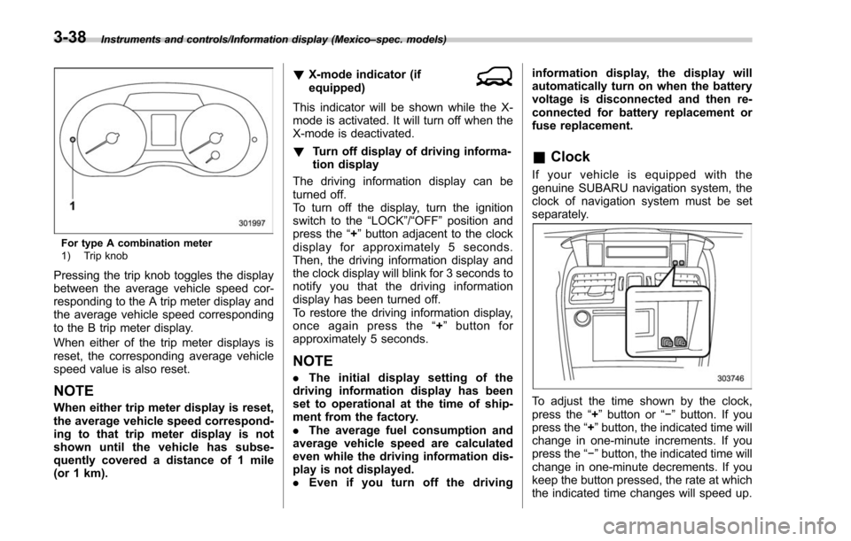
For type A combination meter
1) Trip knob
Pressing the trip knob toggles the display
between the average vehicle speed cor-
responding to the A trip meter display and
the average vehicle speed corresponding
to the B trip meter display.
When either of the trip meter displays is
reset, the corresponding average vehicle
speed value is also reset.
NOTE
When either trip meter display is reset,
the average vehicle speed correspond-
ing to that trip meter display is not
shown until the vehicle has subse-
quently covered a distance of 1 mile
(or 1 km). !
X-mode indicator (if
equipped)
This indicator will be shown while the X-
mode is activated. It will turn off when the
X-mode is deactivated.
! Turn off display of driving informa-
tion display
The driving information display can be
turned off.
To turn off the display, turn the ignition
switch to the “LOCK”/“OFF”position and
press the “+”button adjacent to the clock
display for approximately 5 seconds.
Then, the driving information display and
the clock display will blink for 3 seconds to
notify you that the driving information
display has been turned off.
To restore the driving information display,
once again press the “+ ” button for
approximately 5 seconds.
NOTE
. The initial display setting of the
driving information display has been
set to operational at the time of ship-
ment from the factory.
. The average fuel consumption and
average vehicle speed are calculated
even while the driving information dis-
play is not displayed.
. Even if you turn off the driving information display, the display will
automatically turn on when the battery
voltage is disconnected and then re-
connected for battery replacement or
fuse replacement.
&
Clock
If your vehicle is equipped with the
genuine SUBARU navigation system, the
clock of navigation system must be set
separately.
To adjust the time shown by the clock,
press the “+”button or “− ” button. If you
press the “+ ”button, the indicated time will
change in one-minute increments. If you
press the “− ”button, the indicated time will
change in one-minute decrements. If you
keep the button pressed, the rate at which
the indicated time changes will speed up.
3-38
Page 192 of 634
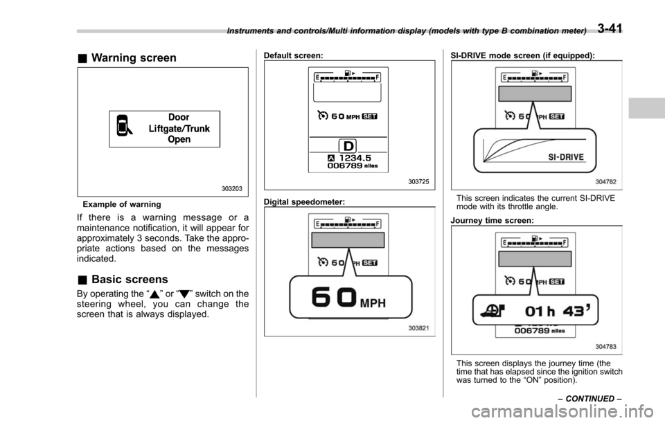
&Warning screen
Example of warning
If there is a warning message or a
maintenance notification, it will appear for
approximately 3 seconds. Take the appro-
priate actions based on the messages
indicated.
&Basic screens
By operating the “”or “”switch on the
steering wheel, you can change the
screen that is always displayed.
Default screen:
Digital speedometer:
SI-DRIVE mode screen (if equipped):
This screen indicates the current SI-DRIVE
mode with its throttle angle.
Journey time screen:
This screen displays the journey time (the
time that has elapsed since the ignition switch
was turned to the “ON ”position).
Instruments and controls/Multi information display (models with type B combination meter)
–CONTINUED –
3-41
Page 210 of 634
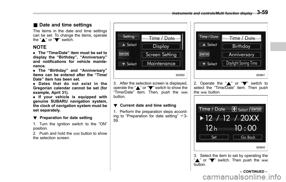
&Date and time settings
The items in the date and time settings
can be set. To change the items, operate
the “
”or “”switch.
NOTE
. The “Time/Date ”item must be set to
display the “Birthday ”, “Anniversary ”
and notifications for vehicle mainte-
nance.
. The “Birthday ”and “Anniversary ”
items can be entered after the “Time/
Date ”item has been set.
. Dates that do not exist in the
Gregorian calendar cannot be set (for
example, April 31).
. If your vehicle is equipped with
genuine SUBARU navigation system,
the clock of navigation system must be
set separately.
! Preparation for date setting
1. Turn the ignition switch to the “ON”
position.
2. Push and hold the
button to show
the selection screen.
3. After the selection screen is displayed,
operate the “”or “”switch to show the
“Time/Date ”item. Then, push the
button.
! Current date and time setting
1. Perform the preparation steps accord-
ing to “Preparation for date setting ”F 3-
59.
2. Operate the “”or “”switch to
select the “Time/Date”item. Then push
the
button.
3. Select the item to set by operating the
“” or “”switch. Then push thebutton.
Instruments and controls/Multi function display
–CONTINUED –3-59