2017 SUBARU FORESTER tires
[x] Cancel search: tiresPage 198 of 634

Type A combination meter
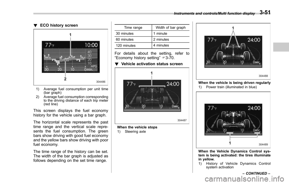
1) Engine oil: Checks the interval of engineoil replacement.
2) Oil filter: Checks the interval of oil filter replacement.
3) Tires: Checks the interval of tire rotation.
4) Inspection and maintenance: Checks the interval of inspection and maintenance.Type B combination meter
1) Windshield washer fluid: Checks thelevel of windshield washer fluid.
2) Brake fluid: Checks the level of brake fluid.
3) Engine oil: Checks the interval of engine oil replacement.
4) Oil filter: Checks the interval of oil filter replacement.
5) Tires: Checks the interval of tire rotation.
6) Inspection and maintenance: Checks the interval of inspection and maintenance.
When the checks are performed, the color
of the icon corresponding to the checked
item will turn green.
If there is no warning message, the self-
check will complete without notification.
Example of notification
If there is a warning message or a
maintenance notification, the color of the
icon corresponding to the item will turn
yellow and the warning message or the
maintenance notification will be displayed.
Take the appropriate actions based on the
messages indicated.
NOTE
.The self-check screen can be set to
on or off. For details, refer to “On/Off
setting ”F 3-77.
. After performing the maintenance,
change the setting of the correspond-
ing maintenance item. For details, refer
to “Maintenance settings ”F 3-76.
. The maintenance notification screen
will be displayed under either of the
Instruments and controls/Multi function display
–CONTINUED –3-47
Page 202 of 634

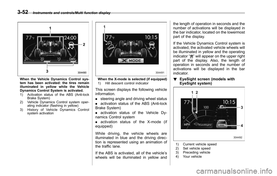
!ECO history screen
1) Average fuel consumption per unit time
(bar graph)
2) Average fuel consumption corresponding to the driving distance of each trip meter
(red line)
This screen displays the fuel economy
history for the vehicle using a bar graph.
The horizontal scale represents the past
time range and the vertical scale repre-
sents the fuel consumption. The green
bars show driving with good fuel economy
and the yellow bars show driving with poor
fuel economy.
The time range of the history can be set.
The width of the bar graph is adjusted as
follows depending on the set time range.
Time range Width of bar graph
30 minutes 1 minute
60 minutes 2 minutes
120 minutes 4 minutes
For details about the setting, refer to
“Economy history setting
”F 3-70.
! Vehicle activation status screen
When the vehicle stops
1) Steering axle
When the vehicle is being driven regularly
1) Power train (illuminated in blue)
When the Vehicle Dynamics Control sys-
tem is being activated: the tires illuminate
in yellow.
1) History of Vehicle Dynamics Control
system activation
Instruments and controls/Multi function display
–CONTINUED –
3-51
Page 203 of 634

Instruments and controls/Multi function display
When the Vehicle Dynamics Control sys-
tem has been activated: the tires remain
illuminated in yellow while the Vehicle
Dynamics Control System is activated.
1) Activation status of the ABS (Anti-lockBrake System)
2) Vehicle Dynamics Control system oper- ating indicator (flashing in yellow)
3) History of Vehicle Dynamics Control system activationWhen the X-mode is selected (if equipped)
1) Hill descent control indicator
This screen displays the following vehicle
information.
.steering angle and driving wheel status
. activation status of the ABS (Anti-lock
Brake System)
. activation status of the Vehicle Dy-
namics Control system
. activation status of the X-mode (if
equipped)
While driving, the vehicle wheels are
illuminated in blue and the driving direc-
tion is represented using an animation of
the traffic lane.
If the ABS is activated, all of the vehicle’ s
wheels will be illuminated in yellow and the length of operation in seconds and the
number of activations will be displayed in
the bar indicator, located on the lowermost
part of the display.
If the Vehicle Dynamics Control system is
activated, the activated vehicle wheels will
be illuminated in yellow and the operating
indicator
“
”will appear on the upper right
part of the display. Also, the length of
operation in seconds and the number of
activations will be displayed in the bar
indicator.
! EyeSight screen (models with
EyeSight system)
1) Current vehicle speed
2) Set vehicle speed
3) Preceding vehicle
4) Your vehicle
3-52
Page 208 of 634

Top menuMenu option DescriptionPage
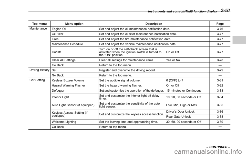
Maintenance Engine Oil Set and adjust the oil maintenance notification date. 3-76
Oil Filter Set and adjust the oil filter maintenance notification date. 3-77
Tires Set and adjust the tire maintenance notification date. 3-77
Maintenance Schedule Set and adjust the vehicle maintenance notification date. 3-77
On/Off Turn on or off the self-check screen that is
activated when the ignition switch is turned to
the
“ON ”position. On or Off
3-77
Clear All Settings Clear all settings for maintenance items. Yes or No 3-78
Go Back Return to the top menu. —
Driving History Set Register and overwrite the driving record. 3-79
Go Back Return to the top menu. —
Car Setting Keyless Buzzer Volume Set the audible signal volume. 0 (OFF) to 73-81
Hazard Warning Flasher Set the hazard warning flasher. On or Off3-82
Defogger Set and customize the operation of the defogger. 15 minutes or Continuous 3-83
Interior Light Set and customize the interior light off delay
timer. 10, 20, 30 seconds or Off
3-84
Auto Light Sensor (if equipped) Set and customize the sensitivity of the auto
light sensor. Low, Mid, High or Max
3-85
Keyless Access Setting (if
equipped) Set and customize the keyless access function. Driver
’s Door Unlock 3-86
Rear Gate Unlock 3-88
Welcome Lighting Set the leaving time and approaching time. 30, 60, 90 seconds or Off 3-89
Go Back Return to top menu. —
Instruments and controls/Multi function display
–CONTINUED –
3-57
Page 228 of 634

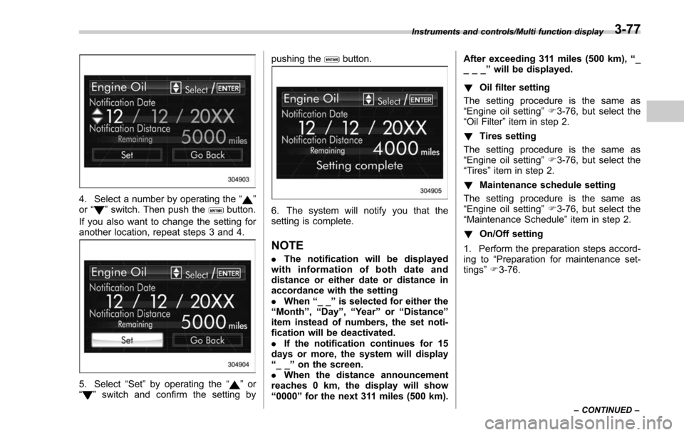
4. Select a number by operating the“”
or “”switch. Then push thebutton.
If you also want to change the setting for
another location, repeat steps 3 and 4.
5. Select “Set”by operating the “”or
“” switch and confirm the setting by pushing the
button.
6. The system will notify you that the
setting is complete.
NOTE
.
The notification will be displayed
with information of both date and
distance or either date or distance in
accordance with the setting
. When “__”is selected for either the
“ Month ”, “Day ”,“Year ”or “Distance”
item instead of numbers, the set noti-
fication will be deactivated.
. If the notification continues for 15
days or more, the system will display
“ __ ”on the screen.
. When the distance announcement
reaches 0 km, the display will show
“ 0000 ”for the next 311 miles (500 km). After exceeding 311 miles (500 km),
“_
___ ”will be displayed.
! Oil filter setting
The setting procedure is the same as
“Engine oil setting ”F 3-76, but select the
“Oil Filter ”item in step 2.
! Tires setting
The setting procedure is the same as
“Engine oil setting ”F 3-76, but select the
“Tires ”item in step 2.
! Maintenance schedule setting
The setting procedure is the same as
“Engine oil setting ”F 3-76, but select the
“Maintenance Schedule ”item in step 2.
! On/Off setting
1. Perform the preparation steps accord-
ing to “Preparation for maintenance set-
tings ”F 3-76.
Instruments and controls/Multi function display
–CONTINUED –3-77
Page 411 of 634

Starting and operating/Preparing to drive
.A vehiclefails the OBDII inspection if
the “CHECK ENGINE ”warning light is not
properly operating (light is illuminated or is
not working due to a burned out bulb) or
there is one or more diagnostic trouble
codes stored in the vehicle’ s computer.
. A state emission inspection may reject
(not pass or fail) a vehicle if the number of
OBDII system readiness monitors “NOT
READY ”is greater than one. If the
vehicle’ s battery has been recently re-
placed or disconnected, the OBDII system
inspection may indicate that the vehicle is
not ready for the emission test. Under this
condition, the vehicle driver should be
instructed to drive his/her vehicle for a few
days to reset the readiness monitors and
return for an emission re-inspection.
. Owners of rejected or failing vehicles
should contact their SUBARU Dealer for
service.
Some states still use dynamometers in
their emission inspection program. A
dynamometer is a treadmill or roller-like
testing device that allows your vehicle ’s
wheels to turn while the vehicle remains in
one place. Prior to your vehicle being put
on a dynamometer, tell your emission
inspector
not to place your SUBARU
AWD vehicle on a two-wheel dynam-
ometer. Otherwise, serious transmis-
sion damage will result. The U.S. Environmental Protection
Agency (EPA) and states using two-wheel
dynamometers in their emission testing
program have EXEMPTED SUBARU
AWD vehicles from the portion of the
testing program that involves a two-wheel
dynamometer. There are some states that
use four-wheel dynamometers in their
testing program. When properly used, this
equipment should not damage a SUBARU
AWD vehicle.
Under no circumstances should the rear
wheels be jacked off the ground, nor
should the driveshaft be disconnected for
state emission testing.
Preparing to drive
You should perform the following checks
and adjustments every day before you
start driving.
1. Check that all windows, mirrors, and
lights are clean and unobstructed.
2. Check the appearance and condition
of the tires. Also check tires for proper
inflation.
3. Look under the vehicle for any sign of
leaks and check that no small animal is
under the vehicle.
4. Check that no small animal enters the
engine compartment.
5. Check that the hood and rear gate are
fully closed.
6. Check the adjustment of the seat.
7. Check the adjustment of the inside
and outside mirrors.
8. Fasten your seatbelt. Check that your
passengers have fastened their seatbelts.
9. Check the operation of the warning
and indicator lights when the ignition
switch is turned to the
“ON ”position.
10. Check the gauges, indicator and warn-
ing lights after starting the engine.
7-8
Page 442 of 634

2. Apply the parking brake.
3. Check the brake fluid level. For details
about checking the brake fluid level, refer
to“Checking the fluid level ”F 11-18.
. If the brake fluid level is not below the
“MIN ”mark, the EBD system may be
malfunctioning. Drive carefully to the
nearest SUBARU dealer and have the
system inspected.
. If the brake fluid level is below the
“ MIN ”mark, DO NOT drive the vehicle.
Instead, have the vehicle towed to the
nearest SUBARU dealer for repair.
WARNING
. Driving with the brake system
warning light illuminated is dan-
gerous. This indicates your brake
system may not be working
properly. If the light remains
illuminated, have the brakes in-
spected by a SUBARU dealer
immediately.
. If at all in doubt about whether
the brakes are operating prop-
erly, do not drive the vehicle.
Have your vehicle towed to the
nearest SUBARU dealer for re-
pair.
Vehicle Dynamics Control
system
WARNING
Always use the utmost care in
driving –overconfidence because
you are driving a vehicle with the
Vehicle Dynamics Control system
could easily lead to a serious acci-
dent.
CAUTION
. Even if your vehicle is equipped
with Vehicle Dynamics Control
system, winter tires should be
used when driving on snow-cov-
ered or icy roads; in addition,
vehicle speed should be reduced
considerably. Simply having a
Vehicle Dynamics Control sys-
tem does not guarantee that the
vehicle will be able to avoid
accidents in any situation.
. Activation of the Vehicle Dy-
namics Control system is an
indication that the road being
travelled on has a slippery sur-
face; since having Vehicle Dy- namics Control is no guarantee
that full vehicle control will be
maintained at all times and under
all conditions, its activation
should be seen as a sign that
the speed of the vehicle should
be reduced considerably.
. Whenever suspension compo-
nents, steering components, or
an axle are removed from a
vehicle, have an inspection of
that system performed by an
authorized SUBARU dealer.
. The following precautions should
be observed in order to ensure
that the Vehicle Dynamics Con-
trol system is operating properly:
– All four wheels should be
fitted with tires of the same
size, type, and brand. Further-
more, the amount of wear
should be the same for all
four tires.
– Keep the tire pressure at the
proper level as shown on the
vehicle placard attached to
the driver ’s side door pillar.
– Use only the specified tem-
porary spare tire to replace a
flat tire. With a temporary
spare tire, the effectiveness
Starting and operating/Vehicle Dynamics Control system
–CONTINUED –7-39
Page 443 of 634

Starting and operating/Vehicle Dynamics Control system
of the Vehicle Dynamics Con-
trol system is reduced and
this should be taken into ac-
count when driving the vehi-
cle in such a condition.
. If non-matching tires are used,
the Vehicle Dynamics Control
system may not operate cor-
rectly.
. The Vehicle Dynamics Control
system helps prevent unstable
vehicle motion such as skidding
using control of the brakes and
engine power. Do not turn off the
Vehicle Dynamics Control sys-
tem unless it is absolutely ne-
cessary. If you must turn off the
Vehicle Dynamics Control sys-
tem, drive very carefully accord-
ing to the road surface condition.
In the event of wheelspin and/or skidding
on a slippery road surface and/or during
cornering and/or an evasive maneuver,
the Vehicle Dynamics Control system
adjusts the engine’ s output and the
wheels’ respective braking forces to help
maintain traction and directional control.
. Traction Control Function
The traction control function is designed to
prevent spinning of the driving wheels on slippery road surfaces, thereby helping to
maintain traction and directional control.
Activation of this function is shown by
flashing the Vehicle Dynamics Control
operation indicator light.
.
Skid Suppression Function
The skid suppression function is designed
to help maintain directional stability by
suppressing the wheels’ tendency to slide
sideways during steering operations. Acti-
vation of this function is shown by flashing
of the Vehicle Dynamics Control operation
indicator light.
NOTE
. The Vehicle Dynamics Control sys-
tem may be considered normal when
the following conditions occur.
–Slight twitching of the brake
pedal is felt.
– The vehicle or steering wheel
shakes to a small degree.
– An operating sound from the
engine compartment is heard
briefly when starting the engine
and when driving off after starting
the engine.
– The brake pedal seems to jolt
when driving off after starting the
engine. .
In the circumstances shown in the
following list, the vehicle may be less
stable than it feels to the driver. The
Vehicle Dynamics Control System may
therefore operate. Such operation does
not indicate a system malfunction.
–on gravel-covered or rutted
roads
– on unfinished roads
– when the vehicle is towing a
trailer
– when the vehicle is fitted with
snow tires or winter tires
. Activation of the Vehicle Dynamics
Control system will cause operation of
the steering wheel to feel slightly
different compared to that for normal
conditions.
. It is always important to reduce
speed when approaching a corner,
even if your vehicle is equipped with
the Vehicle Dynamics Control system.
. Always turn off the engine before
replacing a tire. Failure to do so may
render the Vehicle Dynamics Control
system unable to operate correctly.
7-40