2017 RENAULT ALASKAN light
[x] Cancel search: lightPage 90 of 340

HEADLIGHT AIMING CONTROL
(where fitted)
Manual type
The headlight aiming control operates when the ig- nition switch is in the ONand the headlight switch is
in the position to allow the headlight axis to be
adjusted according to the driving condition.
When driving with no heavy load/luggage or driving
on aflat road, select the normal position <0>.
If the number of occupants and load/luggage in the
vehicle changes, the headlight axis may become
higher than normal.
If the vehicle is travelling on ahilly road, the head-
lights may directly shine on the rearview and outside mirrors of avehicle ahead or the windscreen of an
oncoming vehicle, which may obscure another driv-
ers’ vision. To adjust to the proper aiming height, turn the switch
accordingly. The higher the number, designated on
the switch, the lower the headlight axis.
Automatic type
For vehicles fitted with an automatic levelling sys-
tem, the headlight axis is controlled automatically.
BATTERY SAVER SYSTEM
(where fitted)
The light reminder chime will sound if the headlight
switch is in either the or position and
when the driver’s door is opened with the ignition
switch in the ACC,OFForLOCK position.
If the ignition switch is placed in the OFForLOCK
position while the headlight switch is in the or
position, the battery saver function will turn off
the lights after aperiod of time to prevent the battery
from being discharged.
CAUTION
Do not leave the lights on when the engine is not
running for extended periods of time to prevent
the battery from being discharged. TURN SIGNAL SWITCH
CAUTION
The turn signal switch will not be cancelled auto-
matically if the steering wheel turning angle does
not exceed the preset amount. After the turn or
lane change, make sure that the turn signal
switch is returned to its original position.
Turn signal
To turn on the turn signals, move the lever up
➀or
down ➁to the point where the lever latches. When
the turn is completed, the turn signal cancels auto-
matically.
Lane change signal
To turn on the lane change signals, move the lever
up ➀ or down
➁to the point where the light be-
gins to flash.
If the lever is moved back to its original position right
after moving up or down, the light will flash 3times. JVI0477XZ NIC2915
2-32 Instruments and controls
Page 91 of 340

To cancel the flashing, move the lever to the oppo-
site direction.
See “Settings” earlier in this section to enable/dis-
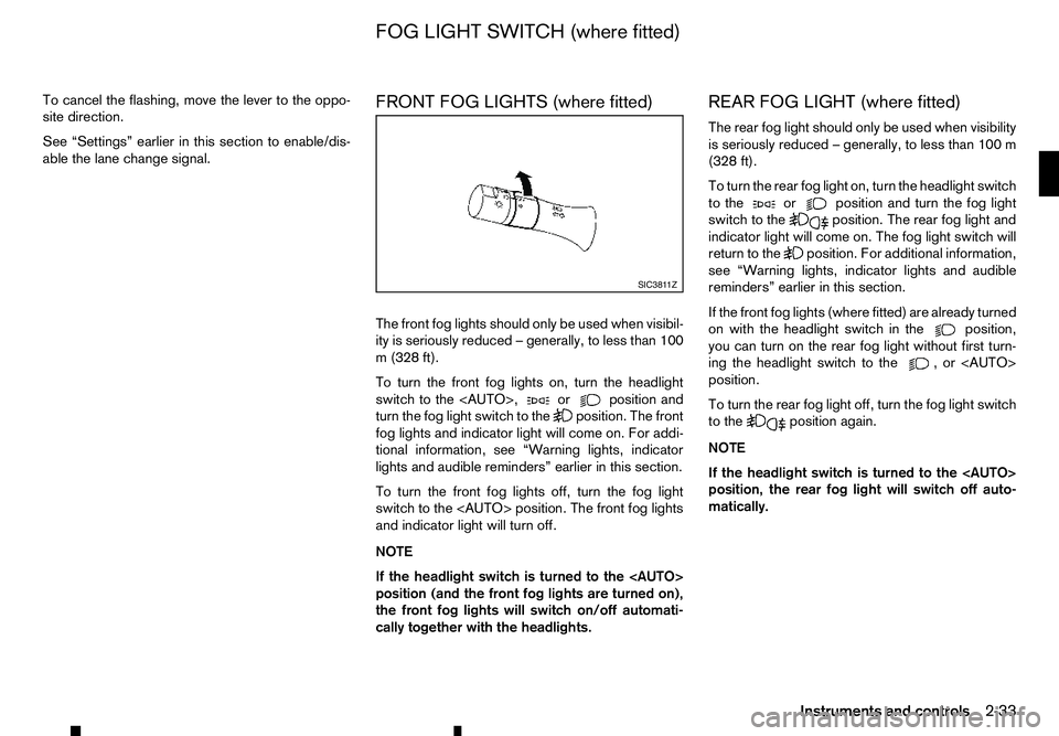
able the lane change signal. FRONT FOG LIGHTS (where fitted)
The front fog lights should only be used when visibil-
ity is seriously reduced
–generally, to less than 100
m( 328 ft).
To turn the front fog lights on, turn the headlight
switch to the
turn the fog light switch to the position. The front
fog lights and indicator light will come on. For addi-
tional information, see “Warning lights, indicator
lights and audible reminders” earlier in this section.
To turn the front fog lights off, turn the fog light
switch to the
and indicator light will turn off.
NOTE
If the headlight switch is turned to the
position (and the front fog lights are turned on),
the front fog lights will switch on/off automati-
cally together with the headlights. REAR FOG LIGHT (where fitted)
The rear fog light should only be used when visibility
is seriously reduced
–generally, to less than 100 m
(328 ft).
To turn the rear fog light on, turn the headlight switch
to the or position and turn the fog light
switch to the position. The rear fog light and
indicator light will come on. The fog light switch will
return to the position. For additional information,
see “Warning lights, indicator lights and audible
reminders” earlier in this section.
If the front fog lights (where fitted) are already turned
on with the headlight switch in the position,
you can turn on the rear fog light without first turn-
ing the headlight switch to the ,o r<
AUTO>
position.
To turn the rear fog light off, turn the fog light switch
to the position again.
NOTE
If the headlight switch is turned to the
position, the rear fog light will switch off auto-
matically. SIC381 1Z
FOG LIGHT SWITCH (where fitted)
Instruments and controls2-33
Page 92 of 340

WARNING
In freezing temperatures, the washer fluid may
freeze on the windscreen and obscure your vi-
sion. Warm the windscreen with the defogger be-
fore you wash the windscreen.
CAUTION
• Do not operate the washer continuously for
longer than 30 seconds.
• Do not operate the washer if the window
washer fluid reservoir is empty.
• If the wiper operation is interrupted by snow
or ice, the wiper may stop moving to protect
its motor. If this occurs, turn the wiper switch
to the OFF position and remove the snow or
ice on and around the wiper arms. In approxi-
mately
1minute, turn the switch on again to
operate the wiper.
WINDSCREEN WIPER AND WASHER
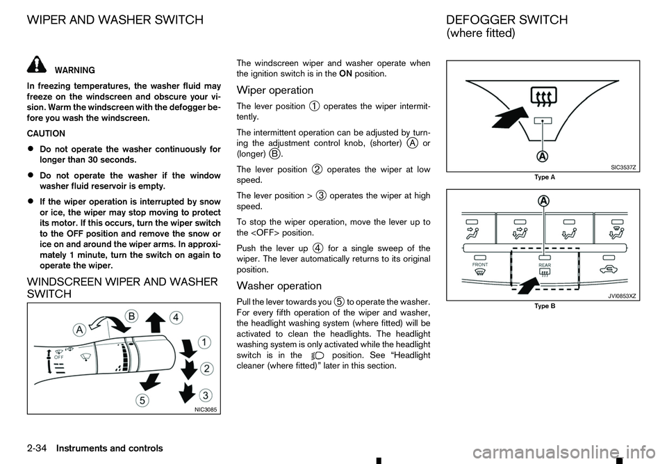
SWITCH The windscreen wiper and washer operate when
the ignition switch is in the
ONposition.
Wiper operation
The lever position ➀operates the wiper intermit-
tently.
The intermittent operation can be adjusted by turn-
ing the adjustment control knob, (shorter) j
Aor
(longer) j
B.
The lever position ➁operates the wiper at low
speed.
The lever position > ➂operates the wiper at high
speed.
To stop the wiper operation, move the lever up to
the
Push the lever up ➃for
asingle sweep of the
wiper. The lever automatically returns to its original
position.
Washer operation
Pull the lever towards you ➄to operate the washer.
For every fifth operation of the wiper and washer,
the headlight washing system (where fitted) will be
activated to clean the headlights. The headlight
washing system is only activated while the headlight
switch is in the position. See “Headlight
cleaner (where fitted)” later in this section. NIC3085 SIC3537Z
Type A
JVI0853XZ
Type B
WIPER AND WASHER SWITCH
DEFOGGER SWITCH
(where fitted)
2-34 Instruments and controls
Page 93 of 340

The rear window defogger switch operates when
the ignition switch is in the ONposition.
The defogger is used to reduce the moisture, fog or
frost on the rear window and outside rearview mir-
ror (where fitted) surfaces to improve the rear view.
When the defogger switch is pushed, the indicator
light j
Ai lluminates and the rear window defogger operates for approximately 15 minutes. After the
preset time has passed, the defogger will turn off
automatically.
To turn the rear window defogger off manually, push
the defogger switch again.
CAUTION
• When operating the defogger continuously,
be sure to start the engine. Otherwise, it may
cause the battery to discharge.
• When cleaning the inner side of the window,
be careful not to scratch or damage the elec-
trical conductors on the surface of the win-
dow. To clean the headlights, pull the windscreen washer
switch towards you while the headlight switch is in
the position and the ignition switch is in the ON
position.
NOTE
The headlight cleaner will automatically operate
every fifth operation of the wiper and washer
switch.
HEADLIGHT CLEANER SWITCH
(where fitted)
The headlight cleaner operates when the headlight
and turn signal switch is in the position and the
ignition switch is in the ON position.
To operate the headlight cleaner push the headlight
cleaner switch located on the driver’s side, lower
left side of the instrument panel.
CAUTION
• Do not operate the cleaner continuously for
more than 15 seconds. NIC3102
Type C-LHD JVI1022XZ
Type C-RHD SIC2255Z
Headlight cleaner switch (where fitted)
HEADLIGHT CLEANER
(where fitted)
Instruments and controls 2-35
Page 96 of 340

If the window does not close
automatically
If the power window automatic function (closing
only) does not operate properly, perform the follow-
ing procedure to initialise the power window sys-
tem.
1. With the engine running.
2. Close the door.
3. Open the window completely by operating the power window switch.
4. Pull the power window switch and hold it to close the window, and then hold the switch more than
3seconds after the window is closed completely.
5. Release the power window switch. Operate the window by the automatic function to confirm the
initialisation is complete.
If the power window automatic function does not
operate properly after performing the procedure above, have your vehicle checked by an approved
dealer or qualified workshop. The power outlet is used to power electrical acces-
sories.
Use the cutoutj
Ab etween the lid and the console
box to route aconnected power cable with the con-
sole box lid closed. WARNING
Do not place any objects on the instrument panel.
Such objects may become dangerous projectiles
and cause injury if asupplemental air bag in-
flates (where fitted).
CAUTION
• Do not leave
apower cable on the instrument
panel in direct sunlight. The surface of the
instrument panel may become very hot result-
ing in damage to the power cable.
• Do not put
aliquid container near the power
outlet. Spilled contents may get into the power
outlet and can result in amalfunction.
• The outlet and plug may be hot during or im-
mediately after use. JVI1023XZ
Instrument panel (upper)
NIC3097
Instrument panel (lower) JVI1025XZ
Console box (where fitted)
POWER OUTLETS
2-38 Instruments and controls
Page 97 of 340

•
This power outlet is not designed for use with
ac igarette lighter unit.
• Do not use accessories that exceed
acom-
bined power draw of 12 volt, 120W (10A)
• Do not use double adapters or more than one
electrical accessory.
• Use this power outlet with the engine running
to avoid discharging the vehicle battery.
• Avoid using when the air conditioner, head-
lights or rear window defogger is on (where
fitted).
• Push the plug in as far as it will go. If good
contact is not made, the plug may overheat or the internal temperature fuse may blow.
• Before inserting or disconnecting
aplug, be
sure that the electrical accessory being used
is turned OFF.
• When not in use, be sure to close the cap. Do
not allow water or any liquid to contact the
outlet. WARNING
• The storage compartments should not be
used while driving so that the full attention
may be given to vehicle operation.
• Keep the storage lids closed while driving to
help prevent injury in an accident or
asudden
stop.
GLOVE BOX
To open the glove box, pull the handle ➀.
To close, push the lid in until the lock latches. CONSOLE BOX
To open the console box lid, push up the knob
j
Aa nd pull up the lid.
To close, push the lid down until the lock latches. JVI1 102XZ JVI1026XZ
STORAGE
Instruments and controls
2-39
Page 98 of 340

SUNGLASSES HOLDER
WARNING
Keep the sunglasses holder closed while driving
to avoid obstructing the driver’s view and to help
prevent an accident.
CAUTION
• Do not use for anything other than sunglasses.
• Do not leave sunglasses in the sunglasses
holder while parking in direct sunlight. The
heat may damage the sunglasses.
To open the sunglasses holder, push and release.
Only store one pair of sunglasses in the holder. CONSOLE SIDE POCKETS
To open the console box lid, push up the knob
j
Aa nd pull up the lid.
To close, push the lid down until the lock latches.
CUP HOLDERS (where fitted) WARNING
The driver must not remove or insert cups into
the cup holder while driving so that full attention
may be given to vehicle operation.
CAUTION
• Avoid abrupt starting and braking especially
when the cup holder is being used to prevent
spilling the contents. If the contents are hot,
they could scald you or your passengers.
• Use only soft cups in the cup holder. Hard
objects can injure you in an accident. Centre console (front separate seat
models)
Soft bottle holder
The front and rear (where fitted) soft bottle holders
are located on the doors.
JVI0619XZ NIC3099
NIC3100
JVI1241XZ
Example
2-40 Instruments and controls
Page 100 of 340

WARNING
• In an accident you could be thrown from the
vehicle through an open sunroof. Adults
should always use seat belts and children
should always use seat belts or child restraint
systems.
• Never allow anyone to stand up or extend any
portion of their body out of the opening while
the vehicle is in motion or while the sunroof is
closing.
CAUTION
• Remove water drops, snow, ice or sand from
the sunroof before opening.
• Do not place any heavy objects on the sunroof
or surrounding area.
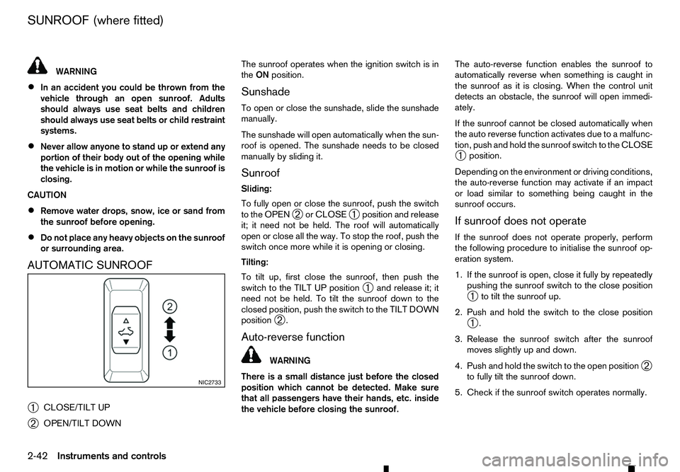
AUTOMATIC SUNROOF
➀ CLOSE/TILT UP
➁ OPEN/TILT DOWN The sunroof operates when the ignition switch is in
the
ON position.
Sunshade
To open or close the sunshade, slide the sunshade
manually.
The sunshade will open automatically when the sun-
roof is opened. The sunshade needs to be closed
manually by sliding it. Sunroof
Sliding:
To fully open or close the sunroof, push the switch
to the OPEN ➁or CLOSE
➀position and release
it; it need not be held. The roof will automatically
open or close all the way. To stop the roof, push the
switch once more while it is opening or closing.
Tilting:
To tilt up, first close the sunroof, then push the
switch to the TILT UP position ➀and release it; it
need not be held. To tilt the sunroof down to the
closed position, push the switch to the TILT DOWN
position ➁.
Auto-reverse function WARNING
There is
as mall distance just before the closed
position which cannot be detected. Make sure
that all passengers have their hands, etc. inside
the vehicle before closing the sunroof. The auto-reverse function enables the sunroof to
automatically reverse when something is caught in
the sunroof as it is closing. When the control unit
detects an obstacle, the sunroof will open immedi-
ately.
If the sunroof cannot be closed automatically when
the auto reverse function activates due to
amalfunc-
tion, push and hold the sunroof switch to the CLOSE
➀ position.
Depending on the environment or driving conditions,
the auto-reverse function may activate if an impact
or load similar to something being caught in the
sunroof occurs.
If sunroof does not operate
If the sunroof does not operate properly, perform
the following procedure to initialise the sunroof op-
eration system.
1. If the sunroof is open, close it fully by repeatedly pushing the sunroof switch to the close position
➀ to tilt the sunroof up.
2. Push and hold the switch to the close position ➀.
3. Release the sunroof switch after the sunroof moves slightly up and down.
4. Push and hold the switch to the open position ➁
to fully tilt the sunroof down.
5. Check if the sunroof switch operates normally. NIC2733
SUNROOF (where fitted)
2-42 Instruments and controls