2017 Ram ProMaster warning light
[x] Cancel search: warning lightPage 54 of 348

WARNING!
An improperly attached, damaged, folded, or stacked
floor mat, or damaged floor mat fasteners may cause
your floor mat to interfere with the accelerator, brake,
or clutch pedals and cause a loss of vehicle control. To
prevent SERIOUS INJURY or DEATH:
•ALWAYS securely attach
your floor mat using
the floor mat fasteners. DO NOT install your floor
mat upside down or turn your floor mat over.
Lightly pull to confirm mat is secured using the
floor mat fasteners on a regular basis.
• ALWAYS REMOVE THE EXISTING FLOOR MAT
FROM THE VEHICLE
before installing any
other floor mat. NEVER install or stack an addi-
tional floor mat on top of an existing floor mat.
• ONLY install floor mats designed to fit your vehicle.
NEVER install a floor mat that cannot be properly
attached and secured to your vehicle. If a floor mat
needs to be replaced, only use a FCA approved floor
mat for the specific make, model, and year of your
vehicle.
• ONLY use the driver ’s side floor mat on the driver ’s
side floor area. To check for interference, with the
(Continued)
WARNING! (Continued)
vehicle properly parked with the engine off, fully
depress the accelerator, the brake, and the clutch
pedal (if present) to check for interference. If your
floor mat interferes with the operation of any pedal,
or is not secure to the floor, remove the floor mat
from the vehicle and place the floor mat in your
trunk.
• ONLY use the passenger ’s side floor mat on the
passenger ’s side floor area.
• ALWAYS make sure objects cannot fall or slide into
the driver ’s side floor area when the vehicle is
moving. Objects can become trapped under accelera-
tor, brake, or clutch pedals and could cause a loss of
vehicle control.
• NEVER place any objects under the floor mat (e.g.,
towels, keys, etc.). These objects could change the
position of the floor mat and may cause interference
with the accelerator, brake, or clutch pedals.
• If the vehicle carpet has been removed and re-
installed, always properly attach carpet to the floor
and check the floor mat fasteners are secure to the
vehicle carpet. Fully depress each pedal to check for
(Continued)
52 THINGS TO KNOW BEFORE STARTING YOUR VEHICLE
Page 55 of 348

WARNING!(Continued)
interference with the accelerator, brake, or clutch
pedals then re-install the floor mats.
• It is recommended to only use mild soap and water
to clean your floor mats. After cleaning, always check
your floor mat has been properly installed and is
secured to your vehicle using the floor mat fasteners
by lightly pulling mat.
Periodic Safety Checks You Should Make Outside
The Vehicle
Tires
Examine tires for excessive tread wear and uneven wear
patterns. Check for stones, nails, glass, or other objects
lodged in the tread or sidewall. Inspect the tread for cuts
and cracks. Inspect sidewalls for cuts, cracks, and bulges.
Check the wheel bolts for tightness. Check the tires (includ-
ing spare) for proper cold inflation pressure.
Lights
Have someone observe the operation of brake lights and
exterior lights while you work the controls. Check turn
signal and high beam indicator lights on the instrument
panel.
Door Latches
Check for proper closing, latching, and locking.
Fluid Leaks
Check area under vehicle after overnight parking for fuel,
engine coolant, oil, or other fluid leaks. Also, if gasoline
fumes are detected or if fuel, power steering fluid (if
equipped), or brake fluid leaks are suspected. The cause
should be located and corrected immediately.
2
THINGS TO KNOW BEFORE STARTING YOUR VEHICLE 53
Page 60 of 348

MIRRORS
Inside Day/Night Mirror — If Equipped
A two-point pivot system allows for horizontal and vertical
adjustment of the mirror. Adjust the mirror to center on the
view through the rear window.
Headlight glare can be reduced by moving the small
control under the mirror to the night position (toward the
rear of the vehicle). The mirror should be adjusted while
set in the day position (toward the windshield).
Outside Mirrors
To receive maximum benefit, adjust the outside mirror(s) to
center on the adjacent lane of traffic with a slight overlap of
the view obtained on the inside mirror.
WARNING!
Vehicles and other objects seen in an outside convex
mirror will look smaller and farther away than they
really are. Relying too much on side convex mirrors
could cause you to collide with another vehicle or other
object. Use your inside mirror when judging the size or
distance of a vehicle seen in a side convex mirror.
Outside Mirrors Folding Feature
All outside mirrors are hinged and may be moved either
forward or rearward to resist damage. The hinges have
three detent positions:
•Full forward position
• Full rearward position
• Normal position
Manual Rearview Mirror
58 UNDERSTANDING THE FEATURES OF YOUR VEHICLE
Page 66 of 348

position the seatback as desired. To return the seatback to
its normal upright position, lean forward, rotate the knob
forward until the seatback is in the upright position.
Recliner Adjustment — With Swivel Seat
The recliner lever is located at the lower front outboard
side of the seat. To recline the seatback, lean forward
slightly, pull the lever outward, lean back to the desired
position and release the lever. To return the seatback to its
normal upright position, lean forward and pull the lever
outward. Release the lever once the seatback is in the
upright position.
WARNING!
•Adjusting a seat while the vehicle is moving is
dangerous. The sudden movement of the seat could
cause you to lose control. The seat belt might not be
adjusted properly and you could be injured. Adjust
the seat only while the vehicle is parked.
• Do not ride with the seatback reclined so that the
shoulder belt is no longer resting against your chest.
(Continued)
Recliner Knob
Recliner Lever
64 UNDERSTANDING THE FEATURES OF YOUR VEHICLE
Page 68 of 348

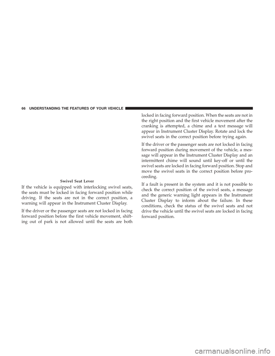
If the vehicle is equipped with interlocking swivel seats,
the seats must be locked in facing forward position while
driving. If the seats are not in the correct position, a
warning will appear in the Instrument Cluster Display.
If the driver or the passenger seats are not locked in facing
forward position before the first vehicle movement, shift-
ing out of park is not allowed until the seats are bothlocked in facing forward position. When the seats are not in
the right position and the first vehicle movement after the
cranking is attempted, a chime and a text message will
appear in Instrument Cluster Display. Rotate and lock the
swivel seats in the correct position before trying again.
If the driver or the passenger seats are not locked in facing
forward position during movement of the vehicle, a mes-
sage will appear in the Instrument Cluster Display and an
intermittent chime will sound until key-off or until the
swivel seats are locked in facing forward position. Stop and
move the swivel seats in the correct position before pro-
ceeding.
If a fault is present in the system and it is not possible to
check the correct position of the swivel seats, a message
and the generic warning light appears in the Instrument
Cluster Display to inform about the failure. In these
conditions, check the status of the swivel seats and not
drive the vehicle until the swivel seats are locked in facing
forward position.
Swivel Seat Lever
66 UNDERSTANDING THE FEATURES OF YOUR VEHICLE
Page 78 of 348

Fog Lights — If Equipped
The fog light switch is located on the center stack
of the instrument panel, just below the climate
controls. Push the switch once to turn the fog
lights on. Push the switch a second time to turn the fog
lights off.
Turn Signals
Move the multifunction lever up or down and the arrows
on each side of the Instrument Cluster Display will flash to
show proper operation of the front and rear turn signal
lights.
NOTE:
If either light remains on and does not flash, or there
is a very fast flash rate, check for a defective outside light
bulb. If an indicator fails to light when the lever is moved, it
would suggest that the indicator bulb is defective.
Parking Lights
These lights can only be turned on with ignition key in the
STOP position or removed, by moving the end of the
multifunction lever to O (off) position and then to the
headlight position. The warning light telltale in the instrument panel comes
on. The lights stay on until the next ignition cycle is
performed.
Lane Change Assist
Tap the lever up or down once, without moving beyond
the detent, and the turn signal (right or left) will flash five
times then automatically turn off.
High Beam/Low Beam Select Switch
Pull the multifunction lever toward you to switch the
headlights to high beam. Pull the lever a second time to
switch the headlights back to low beam.
Flash-To-Pass
You can signal another vehicle with your headlights by
partially pulling the multifunction lever toward the steer-
ing wheel. This will cause the high beam headlights to turn
on until the lever is released.
Follow Me Home/Headlight Delay
When this feature is selected the driver can choose to have
the headlights remain on for a preset period of time.
76 UNDERSTANDING THE FEATURES OF YOUR VEHICLE
Page 79 of 348

Activation
Remove the key or turn the ignition to the OFF/LOCK
position, and pull the multifunction lever toward the
steering wheel, within two minutes. Each time the lever is
pulled, the activation of the lights will be extended by 30
seconds. The activation of the lights can be extended to a
maximum of 210 seconds.
The warning light on the instrument panel will light up
and the corresponding message will appear in the Instru-
ment Cluster Display for as long as the function is acti-
vated. The warning light comes on when the lever is
operated and stays on until the function is automatically
deactivated. Each movement of the lever only increases the
amount of time the lights stay on.
Deactivation
Pull the multifunction lever toward the steering wheel and
hold it for more than two seconds.
Overhead Lights
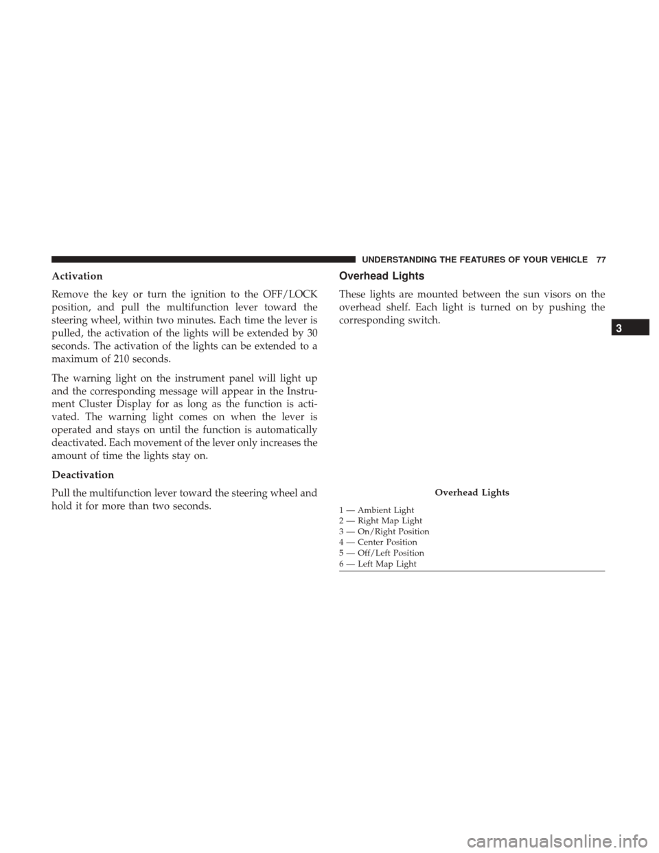
These lights are mounted between the sun visors on the
overhead shelf. Each light is turned on by pushing the
corresponding switch.
Overhead Lights
1 — Ambient Light
2 — Right Map Light
3 — On/Right Position
4 — Center Position
5 — Off/Left Position
6 — Left Map Light
3
UNDERSTANDING THE FEATURES OF YOUR VEHICLE 77
Page 84 of 348

WARNING!(Continued)
driver to lose control of the vehicle. Failure to follow
this warning may result in serious injury or death.
ELECTRONIC SPEED CONTROL
When engaged, the Electronic Speed Control takes over
accelerator operations at speeds greater than 25 mph
(40 km/h) up to the maximum speed of 100 mph
(160 km/h).
The Electronic Speed Control Lever is located on the left
side of the steering column.
NOTE:In order to ensure proper operation, the Electronic
Speed Control System has been designed to shut down if
multiple Speed Control functions are operated at the same
time. If this occurs, the Electronic Speed Control System
can be reactivated by rotating the Electronic Speed Control
ON/OFF center ring and resetting the desired vehicle set
speed.
To Activate
Rotate the center ring upward on the electronic speed
control lever to turn the system ON. The Cruise Indicator
Light in the Instrument Cluster Display will illuminate. To
Electronic Speed Control Lever
82 UNDERSTANDING THE FEATURES OF YOUR VEHICLE