Page 183 of 252
145
F Detach the carrier from the hook and place the spare wheel near the wheel to be
changed.
Removing the wheel with a
punctured tyre
F Unscrew the bolt using the wheelbrace until the carrier is lowered fully. F
R
emove the wheel trim.
F
L
oosen the wheel bolts and start
unscrewing them.
F
P
osition the foot of the jack on the ground
and ensure that it is directly below the
front or rear jacking point provided on the
underbody, whichever is closest to the
wheel to be changed.
F
E
xtend the jack until its head comes into
contact with the jacking point being used;
the vehicle's contact area A must be
engaged in the central part of the head of
the jack. F
Ra
ise the vehicle until there is sufficient
space between the wheel and the ground to
fit the spare (not punctured) wheel easily.
F
R
esume and complete the unscrewing of
the wheel bolts.
F
R
emove the bolts and then remove the
wheel.
8
In the event of a breakdown
Page 184 of 252

146
Fitting the spare wheel
When using a non-uniform spare wheel,
do not exceed 50 mph (80 km/h).
The spare wheel is not designed to
be used over long distances. Have
the tightening of the bolts and the tyre
pressure of the spare wheel checked by a
PEUGEOT dealer or a qualified workshop
as soon as possible.
Also, have the original wheel repaired
and refitted by a PEUGEOT dealer or a
qualified workshop as soon as possible.
F
P
osition the wheel on the hub and start
tightening the bolts by hand.
Ensure that the jack is stable. The foot
of the jack must be in contact with the
ground and directly below the jacking
point used.
If the ground is slippery or loose, the jack
may slip or drop – Risk of injury!
Ensure that the jack is positioned only at
one of jacking points under the vehicle,
making sure that the vehicle's contact
sur face is centred on the head of the jack.
Other wise, there is a risk of damage to the
vehicle and/or of the jack collapsing – Risk
of injury!
Do not extend the jack until you have
started unscrewing the bolts on the wheel
to be changed and have placed the chock
under the wheel diagonally opposite.
F
C
arry out an initial tightening of the bolts
using the wheelbrace.
F
L
ower the vehicle completely by folding the
jack, then remove the jack.
F
T
ighten the wheel bolts again using the
wheelbrace; tighten them fully without
forcing them.
F
P
lace the wheel to be repaired in the carrier.
In the event of a breakdown
Page 185 of 252

147
Never go underneath a vehicle that is
supported only by a jack (use an axle stand).
Never use an electric screwdriver instead of
the wheelbrace.
Refitting the repaired wheel
The wheel is refitted in the same way as the
spare wheel; do not forget to refit the wheel
trim.For more information on Identification
markings
, including the tyre label, refer to
the corresponding section.
For more information on Tyre under-
inflation detection , including
recommendations after changing a wheel
with a tyre under-inflation detection
sensor, refer to the corresponding section.
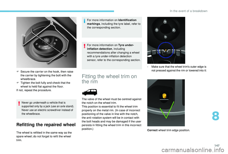
F
S
ecure the carrier on the hook, then raise
the carrier by tightening the bolt with the
wheelbrace.
F
T
ighten the bolt fully and check that the
wheel is held flat against the floor.
If not, repeat the procedure.
Fitting the wheel trim on
the rim
The valve of the wheel must be centred against
the notch on the wheel trim.
This position is essential to fit the wheel trim
properly on the metal rim. (In case of incorrect
positioning of the valve in line with the notch,
the anti-rotation system will be in contact with
the bolt heads and may be damaged if the user
persists in fitting the wheel trim in this incorrect
position.)
- Make sure that the wheel trim's outer edge is not pressed against the rim or lowered into it:
Correct wheel trim edge position.
8
In the event of a breakdown
Page 186 of 252
148
Check the position of the wheel valve
in relation to the ring of the wheel trim.
Incorrect
wheel trim edge position.
-
B
e sure to pre-clip all fixing tabs except the
last (opposite the valve cut-out). -
B
riskly hit with the palm of the hand the tab
opposite the valve (at the location of the last
fixing tab, always in the clipping direction). Incorrect
valve position: below the ring.
Distortion of the edge of the wheel trim at the
valve, due to incorrect fitting.
In the event of a breakdown
Page 187 of 252
149
Comply with the wheel trim fitting
procedure to avoid breaking of the
fixing tab and distor tion on the edge of
the wheel trim.
Correct
valve position: above the ring.
Changing a bulb
Types of bulb
Various types of bulb are fitted to your vehicle.
To remove them:
Ty p e A
All glass bulb: pull gently as it is fitted by
pressure. Ty p e B
Bayonet bulb: press on the bulb then turn it
anti-clockwise.
Ty p e C
Halogen bulb: release the retaining spring from
its housing.
Ty p e D
Light emitting diode (LED): to replace the
daytime running lamps, consult a PEUGEOT
dealer or a qualified workshop.
8
In the event of a breakdown
Page 190 of 252

152
Rear lamps
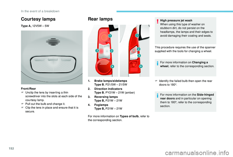
1.Brake lamps/sidelamps
Ty p e B , P21/5W – 21/5W
2. Direction indicators
Ty p e B , PY21W – 21W (amber)
3. Reversing lamps
Ty p e B , P21W – 21W
4. Foglamps
Ty p e B , P21W – 21W
For more information on Types of bulb , refer to
the corresponding section. High pressure jet wash
When using this type of washer on
stubborn dirt, do not persist on the
headlamps, the lamps and their edges to
avoid damaging their coating and seals.
This procedure requires the use of the spanner
supplied with the tools for changing a wheel. For more information on Changing a
wheel , refer to the corresponding section.
F I dentify the failed bulb then open the rear
doors to 180°.
For more information on the Side-hinged
rear doors and in particular on opening
them to 180°, refer to the corresponding
section.
Courtesy lamps
Ty p e A , 12V5W – 5W
Front/Rear
F
U
nclip the lens by inserting a thin
screwdriver into the slots at each side of the
courtesy lamp.
F
P
ull out the bulb and change it.
F
C
lip the lens in place and ensure that it is
secure.
In the event of a breakdown
Page 195 of 252
157
Underbonnet fuses
After opening the bonnet, unclip and tilt the
corresponding box to access the fuses.Fuses
F Amps
A Allocation
1 20Engine management
2 15Horn
3 10Front and rear screenwash pump
4 –
20 Free
LED
5 15Engine components
6 10Steering wheel angle sensor, ESC
7 10Brake switch, clutch switch
8 25Starter
9 10Headlamp adjustment motor, vehicle data recording control unit
10 30Engine components
11 40Free
12 30Wipers
13 40Built-in systems inter face
14 30Pump
15 10Right-hand main beam headlamp
16 10Left-hand main beam headlamp
17 15Right-hand dipped beam headlamp
18 15Left-hand dipped beam headlamp
8
In the event of a breakdown
Page 197 of 252

159
Economy mode
When the engine is switched off and the key is
left in the ignition on position, certain functions
(windscreen wipers, electric windows, courtesy
lamps, audio system, etc.) can be used for a
combined duration of no more than than thirty
minutes, so as not to discharge the battery.
After thirty minutes the active functions are
put on standby and the battery warning lamp
flashes with a message displayed in the screen.
In order to restore the use of these functions
immediately, start the engine and let it run for a
few minutes.
The time available to you will then be double
the period for which the engine is left running.
However, this period will always be between
five and thirty minutes.The engine will not start if the battery is
discharged.
Towing your vehicle
For more information on Changing a
wheel and in particular the tools, refer to
the corresponding section. Vehicles fitted with a manual gearbox
(Diesel version)
For vehicles fitted with a manual gearbox,
the gear lever must be in neutral. Failure
to obser ve this special condition could
result in damage to the transmission and
braking components and to the absence
of braking assistance when the engine is
started again.
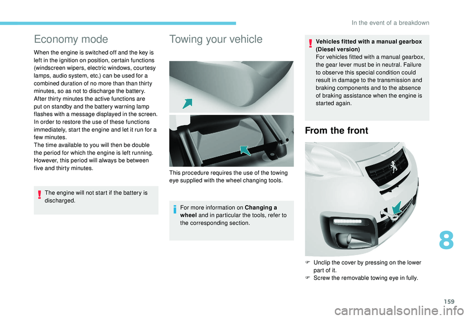
From the front
F Unclip the cover by pressing on the lower
part of it.
F
S
crew the removable towing eye in fully.
This procedure requires the use of the towing
eye supplied with the wheel changing tools.
8
In the event of a breakdown