2017 PEUGEOT 5008 ESP
[x] Cancel search: ESPPage 269 of 404
267
Engine 2.0 HDi
F Fill the fuel tank with at least five litres of Diesel.
F
O
pen the bonnet.
F
I
f necessary, unclip the cover to access the
priming pump.
F
L
oosen the degassing bolt.
F
U
se the priming pump until fuel appears in
the transparent tube.
F
R
etighten the degassing bolt.
F
O
perate the starter until the engine starts (if
the engine does not start at the first attempt,
wait around 15
seconds before trying
again).
F
I
f the engine does not start after a few
attempts, operate the priming pump again
then start the engine.
F
P
ut it back in place, clip in the cover and
ensure it is clipped in.
F
C
lose the boot again.
Tool kit
This is a set of tools provided with the vehicle.
Its content depends on your vehicle's
equipment:
-
t
emporary puncture repair kit,
-
spar
e wheel.
List of tools
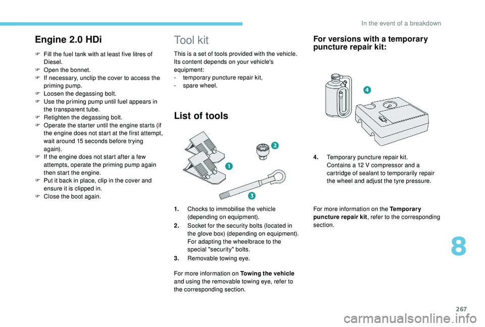
1.Chocks to immobilise the vehicle
(depending on equipment).
2. Socket for the security bolts (located in
the glove box) (depending on equipment).
For adapting the wheelbrace to the
special "security" bolts.
3. Removable towing eye.
For more information on Towing the vehicle
and using the removable towing eye, refer to
the corresponding section.
For versions with a temporary
puncture repair kit:
For more information on the Temporary
puncture repair kit , refer to the corresponding
section. 4. Temporary puncture repair kit.
Contains a 12 V compressor and a
cartridge of sealant to temporarily repair
the wheel and adjust the tyre pressure.
8
In the event of a breakdown
Page 270 of 404
268
For more information on the Spare wheel, refer
to the corresponding section. All of these tools are specific to your
vehicle and may vary depending on
equipment.
Do not use them for any other purposes.
The jack must only be used to change
a wheel with a damaged or punctured tyre.
Do not use any jack other than the one
supplied with this vehicle.
If the vehicle does not have its original
jack, contact a PEUGEOT dealer or a
qualified workshop to obtain the correct
jack for it.
The jack meets European standards,
as defined in the Machinery Directive
2006/42/CE.
The jack does not require any
maintenance.
Access to the tools
Some of the tools are stored beneath the floor
against the boot sill.
The left box contains the wheelbrace and its
extension piece.
The right box contains the wheel chocks and
the towing eye.
To gain access to them:
F
o
pen the boot,
F
f
old the concertina floors back,
F
i
nstall the third row seats,
F
u
nclip the required tools from the boot sill
trim.
For versions with a spare wheel
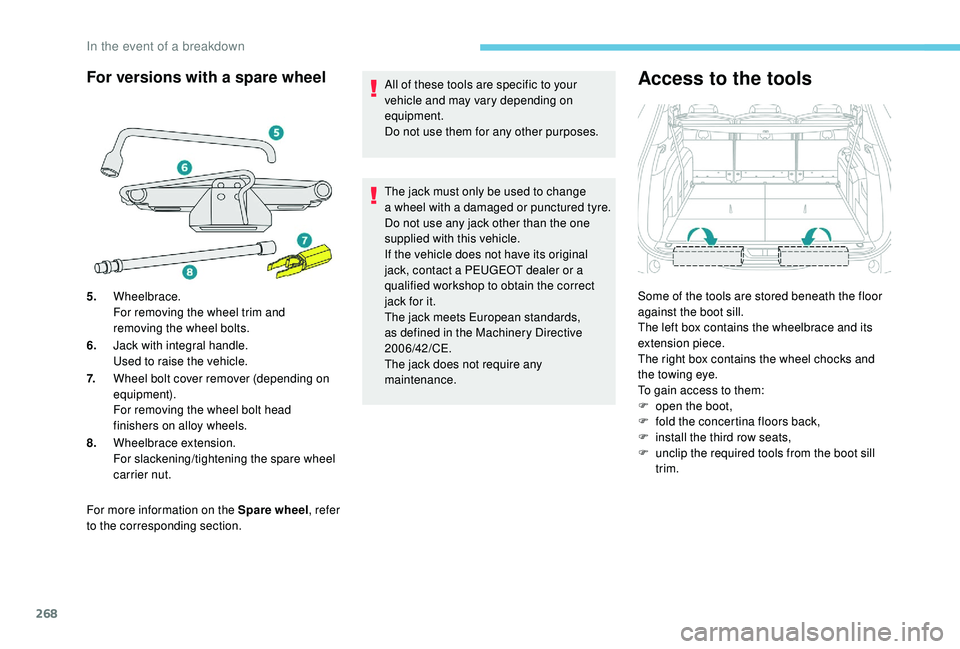
5. Wheelbrace.
For removing the wheel trim and
removing the wheel bolts.
6. Jack with integral handle.
Used to raise the vehicle.
7. Wheel bolt cover remover (depending on
equipment).
For removing the wheel bolt head
finishers on alloy wheels.
8. Wheelbrace extension.
For slackening/tightening the spare wheel
carrier nut.
In the event of a breakdown
Page 271 of 404
269
For versions with a temporary
puncture repair kit
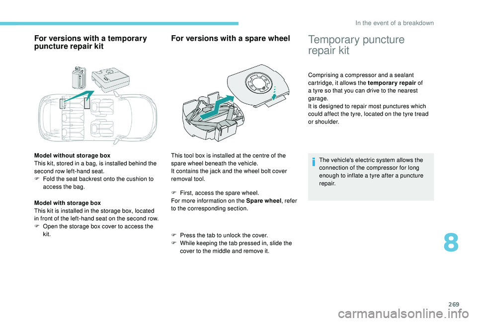
Model without storage box
This kit, stored in a bag, is installed behind the
second row left-hand seat.
F
F
old the seat backrest onto the cushion to
access the bag.
Model with storage box
This kit is installed in the storage box, located
in front of the left-hand seat on the second row.
F
O
pen the storage box cover to access the
kit.
For versions with a spare wheel
F First, access the spare wheel.
For more information on the Spare wheel , refer
to the corresponding section.
F
P
ress the tab to unlock the cover.
F
W
hile keeping the tab pressed in, slide the
cover to the middle and remove it.
This tool box is installed at the centre of the
spare wheel beneath the vehicle.
It contains the jack and the wheel bolt cover
removal tool.
Temporary puncture
repair kit
Comprising a compressor and a sealant
cartridge, it allows the temporary repair
of
a tyre so that you can drive to the nearest
garage.
It is designed to repair most punctures which
could affect the tyre, located on the tyre tread
or shoulder.
The vehicle's electric system allows the
connection of the compressor for long
enough to inflate a tyre after a puncture
repair.
8
In the event of a breakdown
Page 274 of 404
272
Checking / adjusting tyre
pressures
You can also use the compressor,
without injecting sealant, to check and, if
necessary, adjust the tyre pressures
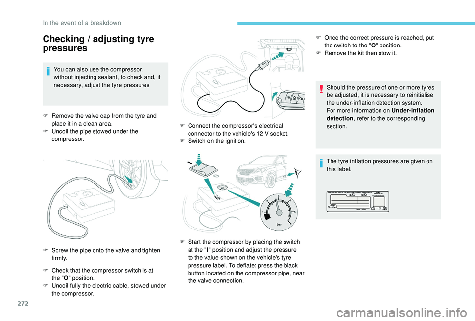
F
R
emove the valve cap from the tyre and
place it in a clean area.
F
U
ncoil the pipe stowed under the
compressor.
F
C
heck that the compressor switch is at
the " O" position.
F
U
ncoil fully the electric cable, stowed under
the compressor. Should the pressure of one or more tyres
be adjusted, it is necessary to reinitialise
the under-inflation detection system.
For more information on Under-inflation
detection
, refer to the corresponding
section.
The tyre inflation pressures are given on
this label.
F
S
crew the pipe onto the valve and tighten
f i r m l y. F
C
onnect the compressor's electrical
connector to the vehicle's 12
V socket.
F
S
witch on the ignition.
F
S
tart the compressor by placing the switch
at the " I" position and adjust the pressure
to the value shown on the vehicle's tyre
pressure label. To deflate: press the black
button located on the compressor pipe, near
the valve connection. F
O
nce the correct pressure is reached, put
the switch to the " O" position.
F
R
emove the kit then stow it.
In the event of a breakdown
Page 281 of 404
279
Front lamps
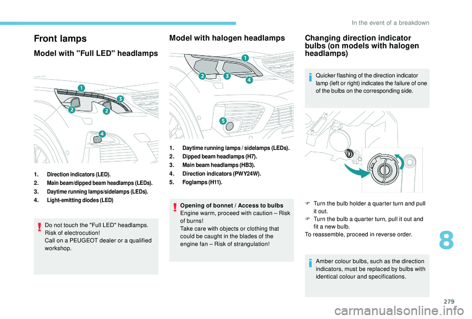
Model with "Full LED" headlamps
1.Direction indicators (LED).
2.Main beam/dipped beam headlamps (LEDs).
3.Daytime running lamps/sidelamps (LEDs).
4.Light-emitting diodes (LED)
Do not touch the "Full LED" headlamps.
Risk of electrocution!
Call on a PEUGEOT dealer or a qualified
workshop.
Model with halogen headlamps
1.Daytime running lamps / sidelamps (LEDs).
2.Dipped beam headlamps (H7).
3.Main beam headlamps (HB3).
4.Direction indicators (PWY24W).
5.Fo g l a m p s ( H11) .
Opening of bonnet / Access to bulbs
Engine warm, proceed with caution – Risk
of burns!
Take care with objects or clothing that
could be caught in the blades of the
engine fan – Risk of strangulation!
Changing direction indicator
bulbs (on models with halogen
headlamps)
Quicker flashing of the direction indicator
lamp (left or right) indicates the failure of one
of the bulbs on the corresponding side.
Amber colour bulbs, such as the direction
indicators, must be replaced by bulbs with
identical colour and specifications.
F
T
urn the bulb holder a quarter turn and pull
it out.
F
T
urn the bulb a quarter turn, pull it out and
fit a new bulb.
To reassemble, proceed in reverse order.
8
In the event of a breakdown
Page 286 of 404
284
Changing a wiper blade
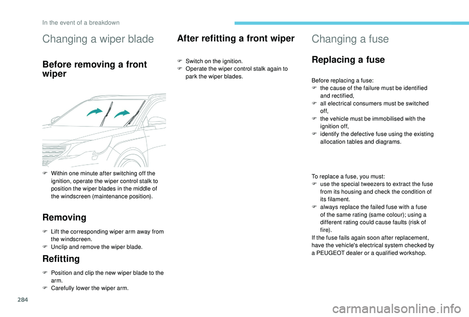
Before removing a front
wiper
Removing
F Lift the corresponding wiper arm away from the windscreen.
F
U
nclip and remove the wiper blade.
Refitting
F Position and clip the new wiper blade to the arm.
F
C
arefully lower the wiper arm.
After refitting a front wiper
F Switch on the ignition.
F O perate the wiper control stalk again to
park the wiper blades.
Changing a fuse
Replacing a fuse
Before replacing a fuse:
F t he cause of the failure must be identified
and rectified,
F
a
ll electrical consumers must be switched
of f,
F
t
he vehicle must be immobilised with the
ignition off,
F
i
dentify the defective fuse using the existing
allocation tables and diagrams.
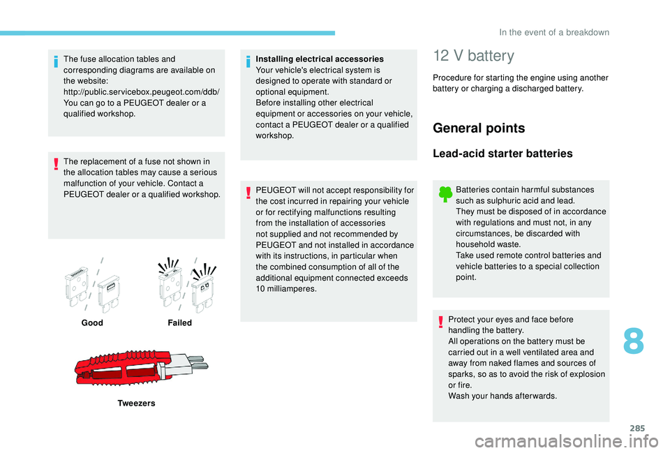
To replace a fuse, you must:
F
u
se the special tweezers to extract the fuse
from its housing and check the condition of
its filament.
F
a
lways replace the failed fuse with a fuse
of the same rating (same colour); using a
different rating could cause faults (risk of
f i r e).
If the fuse fails again soon after replacement,
have the vehicle's electrical system checked by
a PEUGEOT dealer or a qualified workshop.
F
W
ithin one minute after switching off the
ignition, operate the wiper control stalk to
position the wiper blades in the middle of
the windscreen (maintenance position).
In the event of a breakdown
Page 287 of 404
285
The fuse allocation tables and
corresponding diagrams are available on
the website:
http://public.servicebox.peugeot.com/ddb/
You can go to a PEUGEOT dealer or a
qualified workshop.
The replacement of a fuse not shown in
the allocation tables may cause a serious
malfunction of your vehicle. Contact a
PEUGEOT dealer or a qualified workshop.Good Failed
Tw e e z e r s Installing electrical accessories
Your vehicle's electrical system is
designed to operate with standard or
optional equipment.
Before installing other electrical
equipment or accessories on your vehicle,
contact a PEUGEOT dealer or a qualified
workshop.
PEUGEOT will not accept responsibility for
the cost incurred in repairing your vehicle
or for rectifying malfunctions resulting
from the installation of accessories
not supplied and not recommended by
PEUGEOT and not installed in accordance
with its instructions, in particular when
the combined consumption of all of the
additional equipment connected exceeds
10
milliamperes.12 V battery
Procedure for starting the engine using another
battery or charging a discharged battery.
General points
Lead-acid starter batteries
Batteries contain harmful substances
such as sulphuric acid and lead.
They must be disposed of in accordance
with regulations and must not, in any
circumstances, be discarded with
household waste.
Take used remote control batteries and
vehicle batteries to a special collection
point.
Protect your eyes and face before
handling the battery.
All operations on the battery must be
carried out in a well ventilated area and
away from naked flames and sources of
sparks, so as to avoid the risk of explosion
or fire.
Wash your hands afterwards.
8
In the event of a breakdown
Page 291 of 404
289
The Stop & Start system may not be
operational during the trip following the
first engine start.
In this case, the system will only be
available again after a continuous
period of immobilisation of the vehicle,
a period which depends on the exterior
temperature and the state of charge of the
battery (up to about 8 hours).
For right-hand drive vehicles, when the
total distance recorder has reached
60
miles (100 km), it is necessary to wait
approx. 15 minutes before starting the
engine.
However, if minor problems persist following
this operation, contact a PEUGEOT dealer or a
qualified workshop.
Referring to the corresponding section, you
must yourself reinitialise or reset certain
systems, such as:
-
t
he key with remote control or electronic key
(depending on version),
-
t
he sunroof and its electric blind,
-
t
he electric windows,
-
t
he date and time,
-
t
he preset radio stations.
Towing the vehicle
Procedure for having your vehicle towed or
for towing another vehicle using a removable
towing eye.
Access to the tools
Depending on version, the towing eye is stored
either in the interior trim of the boot sill, left-
hand side, or in a bag behind the left rear seat.
For more information on access to the Tool kit
,
refer to the corresponding section.
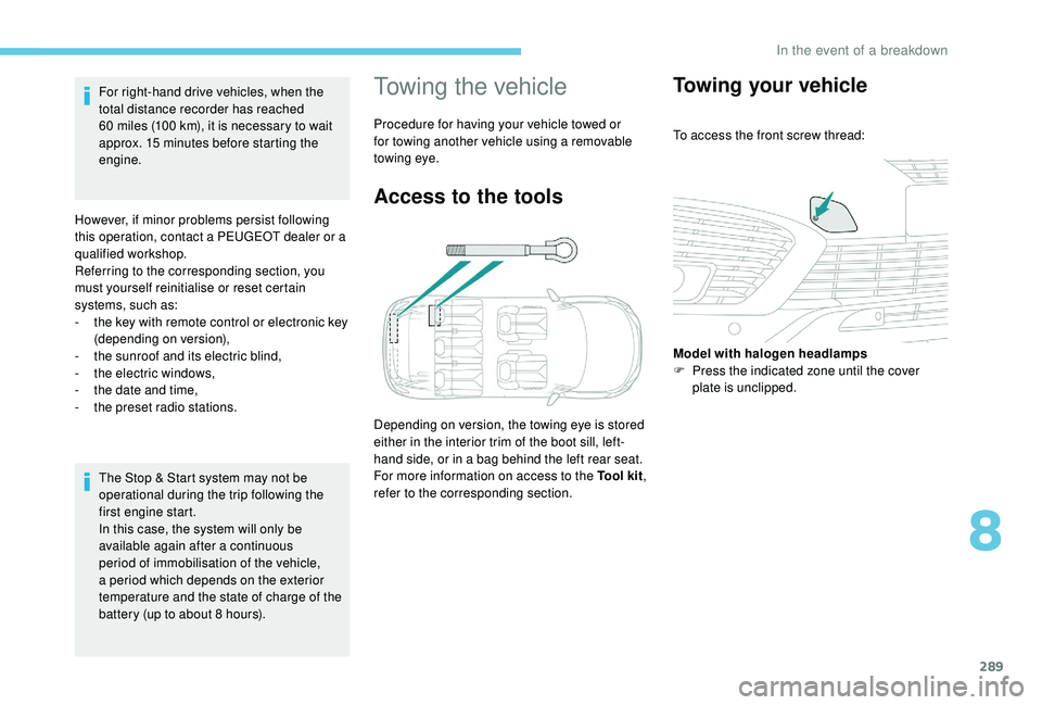
Towing your vehicle
To access the front screw thread:
Model with halogen headlamps
F
P
ress the indicated zone until the cover
plate is unclipped.
8
In the event of a breakdown