Page 257 of 566

255
3008-2_en_Chap06_conduite_ed01-2016
Assisted Lane Departure Warning System
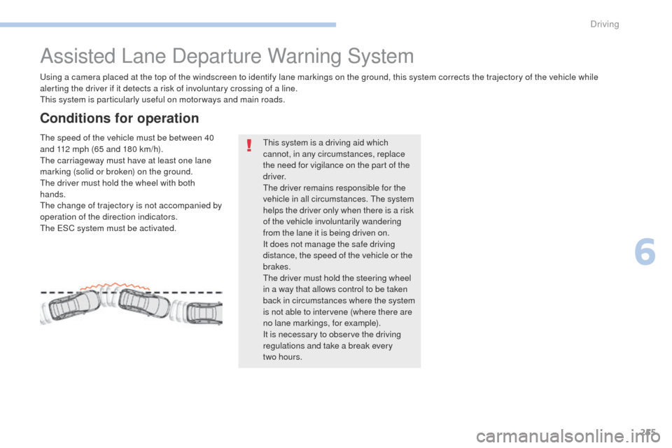
Using a camera placed at the top of the windscreen to identify lane markings on the ground, this system corrects the trajectory of the vehicle while
alerting the driver if it detects a risk of involuntary crossing of a line.
This system is particularly useful on motor ways and main roads.
Conditions for operation
The speed of the vehicle must be between 40
and 112 mph (65 and 180 km/h).
The carriageway must have at least one lane
marking (solid or broken) on the ground.
The driver must hold the wheel with both
hands.
The change of trajectory is not accompanied by
operation of the direction indicators.
The ESC system must be activated.This system is a driving aid which
cannot, in any circumstances, replace
the need for vigilance on the part of the
driver.
The driver remains responsible for the
vehicle in all circumstances. The system
helps the driver only when there is a risk
of the vehicle involuntarily wandering
from the lane it is being driven on.
It does not manage the safe driving
distance, the speed of the vehicle or the
brakes.
The driver must hold the steering wheel
in a way that allows control to be taken
back in circumstances where the system
is not able to intervene (where there are
no lane markings, for example).
It is necessary to observe the driving
regulations and take a break every
two
hours.
6
Driving
Page 258 of 566

256
3008-2_en_Chap06_conduite_ed01-2016
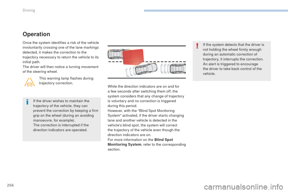
While the direction indicators are on and for
a few seconds after switching them off, the
system considers that any change of trajectory
is voluntary and no correction is triggered
during this period.
However, with the "Blind Spot Monitoring
System" activated, if the driver starts changing
lane and another vehicle is detected in the
vehicle's blind spot, the system will correct
the trajectory of the vehicle even though the
direction indicators are on.
For more information on the Blind Spot
Monitoring System, refer to the corresponding
section. If the system detects that the driver is
not holding the wheel firmly enough
during an automatic correction of
trajectory, it interrupts the correction.
An alert is triggered to encourage
the driver to take back control of the
vehicle.
If the driver wishes to maintain the
trajectory of the vehicle, they can
prevent the correction by keeping a firm
grip on the wheel (during an avoiding
manoeuvre, for example).
The correction is interrupted if the
direction indicators are operated.
Operation
Once the system identifies a risk of the vehicle
involuntarily crossing one of the lane markings
detected, it makes the correction to the
trajectory necessary to return the vehicle to its
initial path.
The driver will then notice a turning movement
of the steering wheel. This warning lamp flashes during
trajectory correction.
Driving
Page 269 of 566

267
3008-2_en_Chap06_conduite_ed01-2016
Visiopark 1
Rear vision
To activate the camera, located in the tailgate,
engage reverse and keep the speed of the
vehicle below 6 mph (10 km/h).
The system is deactivated:
-
a
utomatically above about 6 mph
(10 km/h),
-
a
utomatically on opening the tailgate,
-
w
hen coming out of reverse (the image
remains displayed for 7 seconds),
-
b
y pressing the red cross in the top left-
hand corner of the touch screen.
AUTO mode
This mode is activated by default.
Using sensors in the rear bumper, the
automatic view changes from a rear view to a
view from above, as an obstacle is approached
during a manoeuvre.
Standard view
The area behind the vehicle is displayed in the
screen.
The blue lines represent the width of your
vehicle, with the mirrors unfolded; their
direction changes with the position of the
steering wheel.
The red line represents a distance of 30 cm
from the rear bumper, and the two blue lines,
1 m and 2 m respectively.
This view is available with AUTO mode or in the
view selection menu.
6
Driving
Page 272 of 566

270
3008-2_en_Chap06_conduite_ed01-2016
Front and rear visionAUTO mode
This mode is activated by default.
Using sensors in the front bumper, the
automatic view changes from front view to the
view from above as an obstacle is approached
during a manoeuvre.
Standard view
The area in front of your vehicle is displayed in
the screen.
The blue lines represent the width of your
vehicle, with the mirrors unfolded; their
direction changes with the position of the
steering wheel.
The red line represents a distance of 30 cm
from the front bumper, and the two blue lines,
1 m and 2 m respectively.
This view is available with AUTO mode or in the
view selection menu.
With the engine running and the
speed below 12 mph (20 km/h), the
system is activated in the Driving
menu of the touch screen:
F
Sel
ect " Panoramic visual aid ".
AUTO mode is displayed by default, with front
vision, if the gearbox is in neutral or with a
gear engaged, or with rear vision, if reverse is
engaged.
The system is deactivated:
-
a
utomatically above about 18 mph
(30
km/h) (the image disappears
temporarily from 12 mph (20 km/h)),
-
b
y pressing the red cross in the top left-
hand corner of the touch screen.
Driving
Page 274 of 566

272
3008-2_en_Chap06_conduite_ed01-2016
Park Assist
This system provides active assistance with
parking. It detects a parking space then
operates the steering to park in the space.
It operates the steering while the driver
manages the accelerator, brakes, gears and
clutch (manual gearbox). During phases of
entry into and exit from a parking space, the
system provides visual and audible information
to the driver in order to make the manoeuvres
safe. It may be necessary to move for wards
and backwards more than once.During a manoeuvre, the steering
wheel turns quickly: do not hold the
steering wheel, do not place your
hands between the spokes of the
steering wheel and take care with
loose and bulky clothing (scarves, ties,
handbags...) - Risk of injury!
When Park Assist is activated, it
prevents a change to STOP mode of
Stop & Start. In STOP mode, activation
of Park Assist restarts the engine.
This manoeuvring assistance system
cannot, in any circumstances, replace
the need for vigilance on the part of the
driver.
The driver must remain in control of their
vehicle ensuring that the space remains
clear throughout the manoeuvre.
In some circumstances, the sensors may
not detect small obstacles located in
their blind spots.
The driver can take control at any time by
gripping the steering wheel. The Park Assist system provides assistance for
the following manoeuvres:
A.
E
ntry into a parallel parking space
B.
E
xit from a parallel parking spaceC.
B
ay parking
The Park Assist system cannot work
with the engine off.
Driving
Page 312 of 566
310
3008-2_en_Chap08_en cas-de-panne_ed01-2016
For versions with a spare wheel:
F unclip the carrier box by pulling it up,
F u nclip the two fixings to open its cover. All of these tools are specific to your
vehicle and can vary according to
equipment.
Do not use them for any other
purposes.
The jack must only be used to change
a wheel with a damaged or punctured
tyre.
Do not use any jack other than the one
supplied with this vehicle.
If the vehicle does not have its original
jack, contact a PEUGEOT dealer or a
qualified workshop to obtain the correct
jack for it.
The jack meets European standards,
as defined in the Machinery
Directive
2006/42/CE.
The jack does not require any
maintenance.
In the event of a breakdown
Page 321 of 566

319
3008-2_en_Chap08_en cas-de-panne_ed01-2016
Removing a wheel
* mode P for an automatic gearbox.
List of operations
Parking the vehicle
Immobilise the vehicle where it does not
block traffic: the ground must be level,
stable and non-slippery.
Apply the parking brake unless it has
been programmed to automatic mode,
switch off the ignition and engage first
gear* to lock the wheels.
Check that the braking warning lamps
in the instrument panel are on (not
flashing).
The occupants must get out of the
vehicle and wait where they are safe.
If necessary, place a chock under the
wheel diagonally opposite the wheel to
be changed.
Never go underneath a vehicle raised
using a jack; use an axle stand.
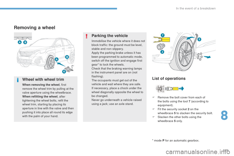
F
R
emove the bolt cover from each of
the bolts using the tool 7 (according to
equipment).
F
F
it the security socket 2 on the
wheelbrace
5 to slacken the security bolt.
F
S
lacken the other bolts using the
wheelbrace 5 o n l y.
Wheel with wheel trim
When removing the wheel , first
remove the wheel trim by pulling at the
valve aperture using the wheelbrace.
When refitting the wheel , after
tightening the wheel bolts, refit the
wheel trim, starting by placing its
aperture in line with the valve and then
pushing it into place all round its edge
with the palm of your hand.
8
In the event of a breakdown
Page 322 of 566

320
3008-2_en_Chap08_en cas-de-panne_ed01-2016
F Place the foot of the jack 6 on the ground and ensure that it is directly below the
front
A or rear B jacking point provided on
the underbody, whichever is closest to the
wheel to be changed.
Ensure that the jack is stable. If the ground is slippery or loose, the jack may slip or drop -
Risk of injury!
Take care to position the jack only at one of the jacking points A or B under the vehicle,
ensuring that the head of the jack is centred under the contact area of the vehicle.
Other wise, there is a risk of damage to the vehicle and/or the jack dropping - Risk of injury! F
R emove the bolts and store them in a clean
place.
F
R
emove the wheel.
F
E xtend the jack 6 until its head comes into
contact with the jacking point A or B used;
the contact area A or B on the vehicle must
be engaged with the central part of the
head of the jack.
F
Ra
ise the vehicle until there is sufficient
space between the wheel and the ground
to admit the spare (not punctured) wheel
easily.
In the event of a breakdown