2017 NISSAN TITAN ECU
[x] Cancel search: ECUPage 518 of 671
Make sure that the secondary latch keeps the
hood from opening when the primary latch is
released.
When driving in areas using road salt or other
corrosive materials, check lubrication frequently.
Lights*:Clean the headlights on a regular basis.
Make sure that the headlights, stop lights, tail
lights, turn signal lights, and other lights are all
operating properly and installed securely. Also
check headlight aim.
Road wheel nuts (lug nuts)*: When checking
the tires, make sure no wheel nuts are missing,
and check for any loose wheel nuts. Tighten if
necessary.
Tire rotation*: Tires should be rotated every
5,000 miles (8,000 km).
Tires*: Check the pressure with a gauge often
and always prior to long distance trips. If neces-
sary, adjust the pressure in all tires, including the
spare, to the pressure specified. Check carefully
for damage, cuts or excessive wear.
Tire Pressure Monitoring System (TPMS)
transmitter components: Replace the TPMS
transmitter grommet seal, valve core and cap
when the tires are replaced due to wear or age.
Wheel alignment and balance: If the vehicle
should pull to either side while driving on a straight and level road, or if you detect uneven or
abnormal tire wear, there may be a need for wheel
alignment. If the steering wheel or seat vibrates at
normal highway speeds, wheel balancing may be
needed.
For additional information regarding tires, refer to
“Important Tire Safety Information” (US) or “Tire
Safety Information” (Canada) in the Warranty In-
formation Booklet.
Windshield:
Clean the windshield on a regular
basis. Check the windshield at least every six
months for cracks or other damage. Have a dam-
aged windshield repaired by a qualified repair
facility.
Windshield wiper blades*: Check for cracks
or wear if they do not wipe properly.
Inside the vehicle
The maintenance items listed here should be
checked on a regular basis, such as when per-
forming scheduled maintenance, cleaning the ve-
hicle, etc.
Accelerator pedal: Check the pedal for smooth
operation and make sure the pedal does not bind
or require uneven effort. Keep the floor mat away
from the pedal.
Automatic transmission P (Park) position
mechanism: On a fairly steep hill check that your vehicle is held securely with the shift lever in
the P (Park) position without applying any brakes.
Brake pedal:
Check the pedal for smooth op-
eration. If the brake pedal suddenly goes down
further than normal, the pedal feels spongy or the
vehicle seems to take longer to stop, have your
vehicle checked immediately. It is recommended
that you visit a NISSAN dealer for this service.
Brakes: Check that the brakes do not pull the
vehicle to one side when applied.
Parking brake: Check the parking brake opera-
tion regularly. The vehicle should be securely held
on a fairly steep hill with only the parking brake
applied. If the parking brake needs adjustment, it
is recommended that you visit a NISSAN dealer
for this service.
Seats: Check seat position controls such as
seat adjusters, seatback recliner, etc., to ensure
they operate smoothly and all latches lock se-
curely in every position. Check that the head
restraints/headrests move up and down
smoothly and the locks (if so equipped) hold
securely in all latched positions.
Seat belts: Check that all parts of the seat belt
system (for example, buckles, anchors, adjusters
and retractors) operate properly and smoothly,
and are installed securely. Check the belt web-
bing for cuts, fraying, wear or damage.
Maintenance and schedules9-3
Page 536 of 671
10 Technical and consumer information
Recommended fluids/lubricants and capacities......10-2
Fuel recommendation .......................... 10-4
Engine oil and oil filter recommendations
(for gas engine only) ........................... 10-7
Air conditioner system refrigerant and oil
recommendations ............................. 10-8
Specifications .................................... 10-8
Engine ....................................... 10-8
Wheels and tires ............................. 10-10
Dimensions and weights ......................10-11
When traveling or registering in another country .....10-15
Vehicle identification ............................. 10-15
Vehicle identification number (VIN) plate ........10-15
Vehicle identification number
(chassis number) ............................. 10-15
Engine serial number .......................... 10-16
F.M.V.S.S./C.M.V.S.S. certification label .........10-16
Emission control information label ..............10-17
Tire and loading information label ...............10-18
Air conditioner specification label ...............10-18
Installing front license plate .......................10-19
Vehicle loading information .......................10-20
Terms ....................................... 10-20
Vehicle load capacity ......................... 10-21Securing the load
............................. 10-22
Utili-track™ channel system (if so equipped) .....10-23
Loading tips ................................. 10-32
Truck-camper loading information .................10-32
Crew cab models ............................. 10-32
Location for center of gravity ...................10-33
Vehicle load weight capacity ...................10-33
Measurement of weights ......................10-33
Towing a trailer .................................. 10-34
Maximum load limits .......................... 10-34
Towing load/specification ......................10-37
Towing safety ................................ 10-41
Flat
towing for 2-Wheel Drive (2WD) vehicle
(if so equipped) .............................. 10-56
Flat towing for 4-Wheel Drive (4WD) vehicle
(if so equipped) .............................. 10-57
Snow plow ..................................... 10-57
Uniform tire quality grading .......................10-58
Emission control system warranty .................10-59
Reporting safety defects ......................... 10-59
Readiness for inspection/maintenance (I/M) test
(gas engine only) ................................ 10-60
Event Data Recorders (EDR) ......................10-61
Owner’s Manual/Service Manual order information . .10-61
Page 557 of 671
Steps for determining correct load
limit
1. Locate the statement “The combinedweight of occupants and cargo
should never exceed XXX lbs or XXX
kg” on your vehicle’s Tire and Load-
ing Information label.
2. Determine the combined weight of the driver and passengers that will be
riding in your vehicle.
3. Subtract the combined weight of the driver and passengers from XXX lbs
or XXX kg.
4. The resulting figure equals the avail- able amount of cargo and luggage
load capacity. For example, if the
XXX amount equals 1,400 lbs. and
there will be five 150 lb. passengers
in your vehicle, the amount of avail-
able cargo and luggage load capac-
ity is 650 lbs. (1,400-750 (5 X 150)
= 650 lbs) or (640-340 (5 X 70) =
300 kg.) 5. Determine the combined weight of
luggage and cargo being loaded on
the vehicle. That weight may not
safely exceed the available cargo and
luggage load capacity calculated in
step 4.
6. If your vehicle will be towing a trailer, load from your trailer will be trans-
ferred to your vehicle. Consult this
manual to determine how this re-
duces the available cargo and lug-
gage load capacity of your vehicle.
Before driving a loaded vehicle, confirm
that you do not exceed the GVWR or the
GAWR for your vehicle. For additional
information, refer to “Measurement of
weights” in this section.
Also check tires for proper inflation pres-
sures. For additional information, refer to
the “Tire and Loading Information label” in
the “Do-it-yourself” section of this
manual.
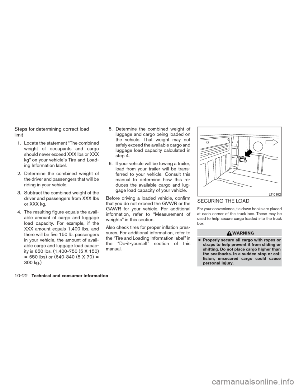
SECURING THE LOAD
For your convenience, tie down hooks are placed
at each corner of the truck box. These may be
used to help secure cargo loaded into the truck
box.
WARNING
● Properly secure all cargo with ropes or
straps to help prevent it from sliding or
shifting. Do not place cargo higher than
the seatbacks. In a sudden stop or col-
lision, unsecured cargo could cause
personal injury.
LTI0102
10-22Technical and consumer information
Page 558 of 671
●Do not load your vehicle any heavier
than the GVWR or the maximum front
and rear GAWRs. If you do, parts of your
vehicle can break, tire damage could
occur, or it can change the way your
vehicle handles. This could result in loss
of control and cause personal injury.
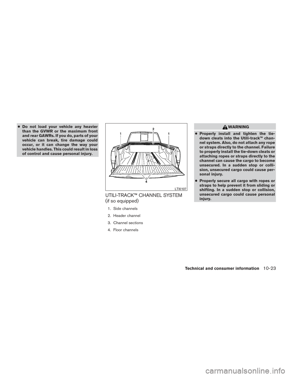
UTILI-TRACK™ CHANNEL SYSTEM
(if so equipped)
1. Side channels
2. Header channel
3. Channel sections
4. Floor channels
WARNING
● Properly install and tighten the tie-
down cleats into the Utili-track™ chan-
nel system. Also, do not attach any rope
or straps directly to the channel. Failure
to properly install the tie-down cleats or
attaching ropes or straps directly to the
channel can cause the cargo to become
unsecured. In a sudden stop or colli-
sion, unsecured cargo could cause per-
sonal injury.
● Properly secure all cargo with ropes or
straps to help prevent it from sliding or
shifting. In a sudden stop or collision,
unsecured cargo could cause personal
injury.
LTI0107
Technical and consumer information10-23
Page 559 of 671
NOTE:
If the bed liner storage bins (if so equipped)
are installed on the vehicle, use type B
cleats in the side channel locations. The
use of type A cleats in the side channel
locations with the bed liner storage bins
installed will interfere with bed liner stor-
age bin lid operation. For additional infor-
mation on bed liner storage bins, refer to
“Storage” in the “Instruments and con-
trols” section of this manual.
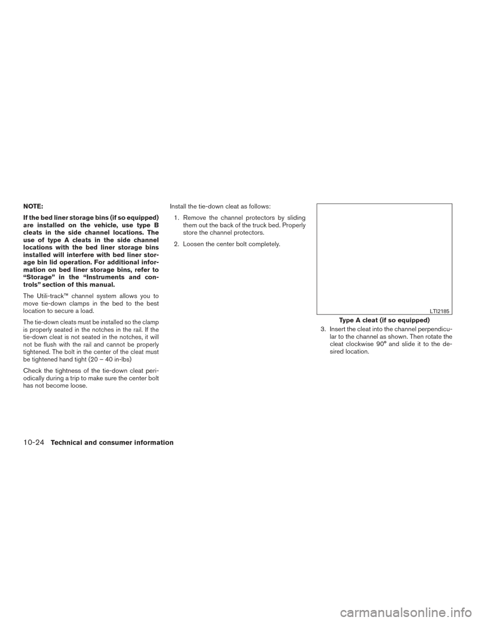
The Utili-track™ channel system allows you to
move tie-down clamps in the bed to the best
location to secure a load.
The tie-down cleats must be installed so the clamp
is properly seated in the notches in the rail. If the
tie-down cleat is not seated in the notches, it will
not be flush with the rail and cannot be properly
tightened. The bolt in the center of the cleat must
be tightened hand tight (20 – 40 in-lbs)
Check the tightness of the tie-down cleat peri-
odically during a trip to make sure the center bolt
has not become loose.Install the tie-down cleat as follows:
1. Remove the channel protectors by sliding them out the back of the truck bed. Properly
store the channel protectors.
2. Loosen the center bolt completely.
3. Insert the cleat into the channel perpendicu-lar to the channel as shown. Then rotate the
cleat clockwise 90° and slide it to the de-
sired location.
Type A cleat (if so equipped)
LTI2185
10-24Technical and consumer information
Page 566 of 671
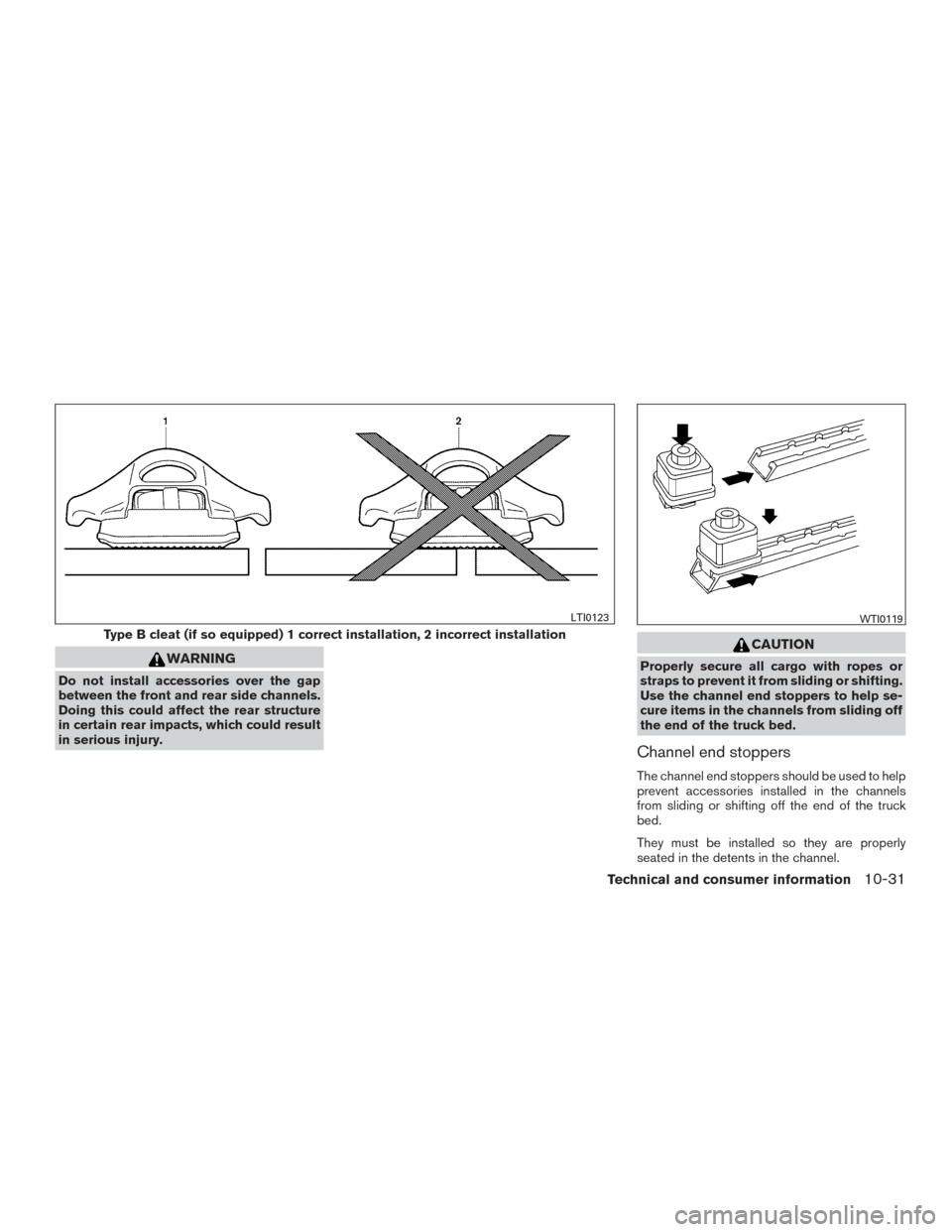
WARNING
Do not install accessories over the gap
between the front and rear side channels.
Doing this could affect the rear structure
in certain rear impacts, which could result
in serious injury.
CAUTION
Properly secure all cargo with ropes or
straps to prevent it from sliding or shifting.
Use the channel end stoppers to help se-
cure items in the channels from sliding off
the end of the truck bed.
Channel end stoppers
The channel end stoppers should be used to help
prevent accessories installed in the channels
from sliding or shifting off the end of the truck
bed.
They must be installed so they are properly
seated in the detents in the channel.
Type B cleat (if so equipped) 1 correct installation, 2 incorrect installation
LTI0123WTI0119
Technical and consumer information10-31
Page 567 of 671
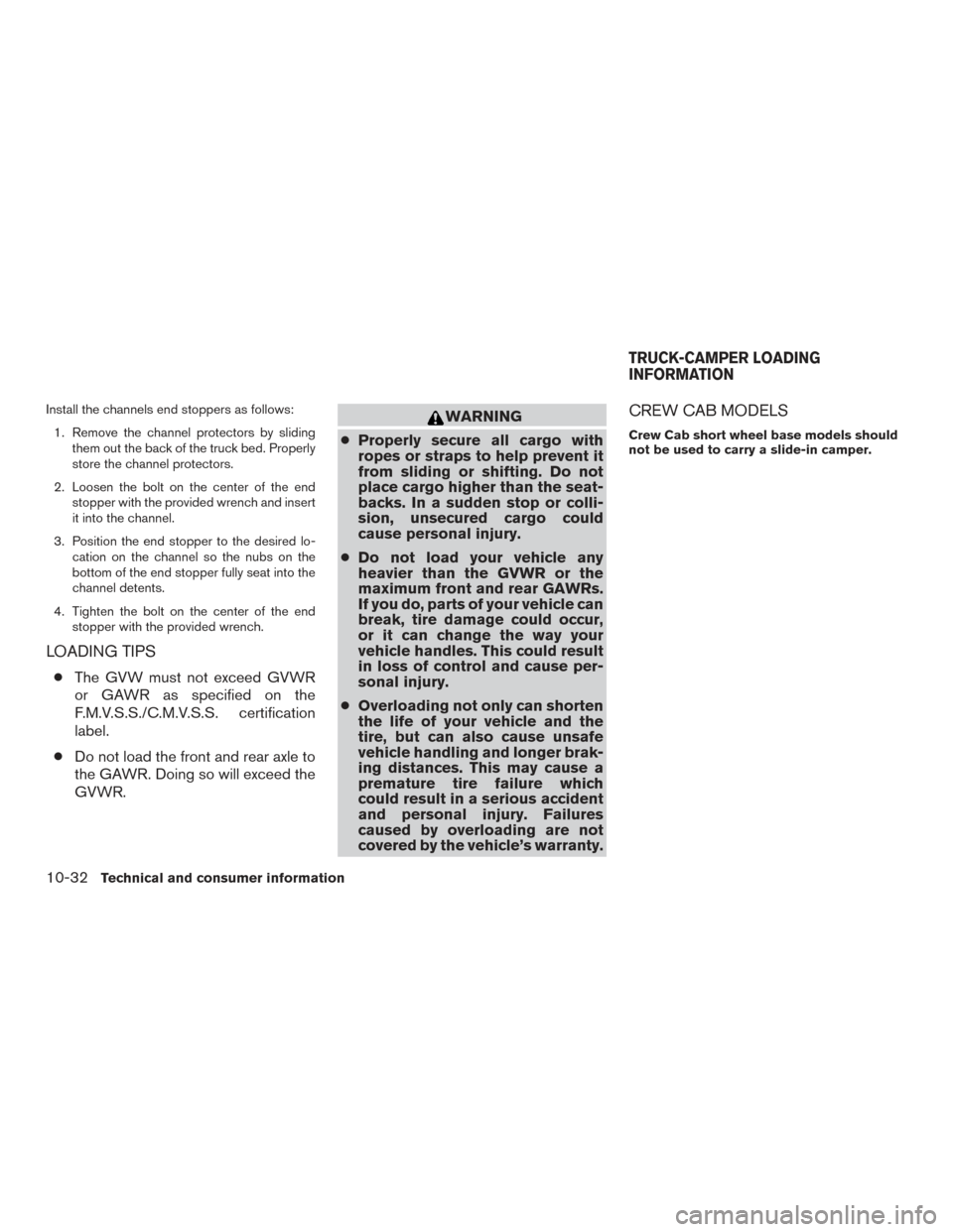
Install the channels end stoppers as follows:1. Remove the channel protectors by sliding them out the back of the truck bed. Properly
store the channel protectors.
2. Loosen the bolt on the center of the end stopper with the provided wrench and insert
it into the channel.
3. Position the end stopper to the desired lo- cation on the channel so the nubs on the
bottom of the end stopper fully seat into the
channel detents.
4. Tighten the bolt on the center of the end stopper with the provided wrench.
LOADING TIPS
●The GVW must not exceed GVWR
or GAWR as specified on the
F.M.V.S.S./C.M.V.S.S. certification
label.
● Do not load the front and rear axle to
the GAWR. Doing so will exceed the
GVWR.
WARNING
● Properly secure all cargo with
ropes or straps to help prevent it
from sliding or shifting. Do not
place cargo higher than the seat-
backs. In a sudden stop or colli-
sion, unsecured cargo could
cause personal injury.
● Do not load your vehicle any
heavier than the GVWR or the
maximum front and rear GAWRs.
If you do, parts of your vehicle can
break, tire damage could occur,
or it can change the way your
vehicle handles. This could result
in loss of control and cause per-
sonal injury.
● Overloading not only can shorten
the life of your vehicle and the
tire, but can also cause unsafe
vehicle handling and longer brak-
ing distances. This may cause a
premature tire failure which
could result in a serious accident
and personal injury. Failures
caused by overloading are not
covered by the vehicle’s warranty.CREW CAB MODELS
Crew Cab short wheel base models should
not be used to carry a slide-in camper.
TRUCK-CAMPER LOADING
INFORMATION
10-32Technical and consumer information
Page 568 of 671
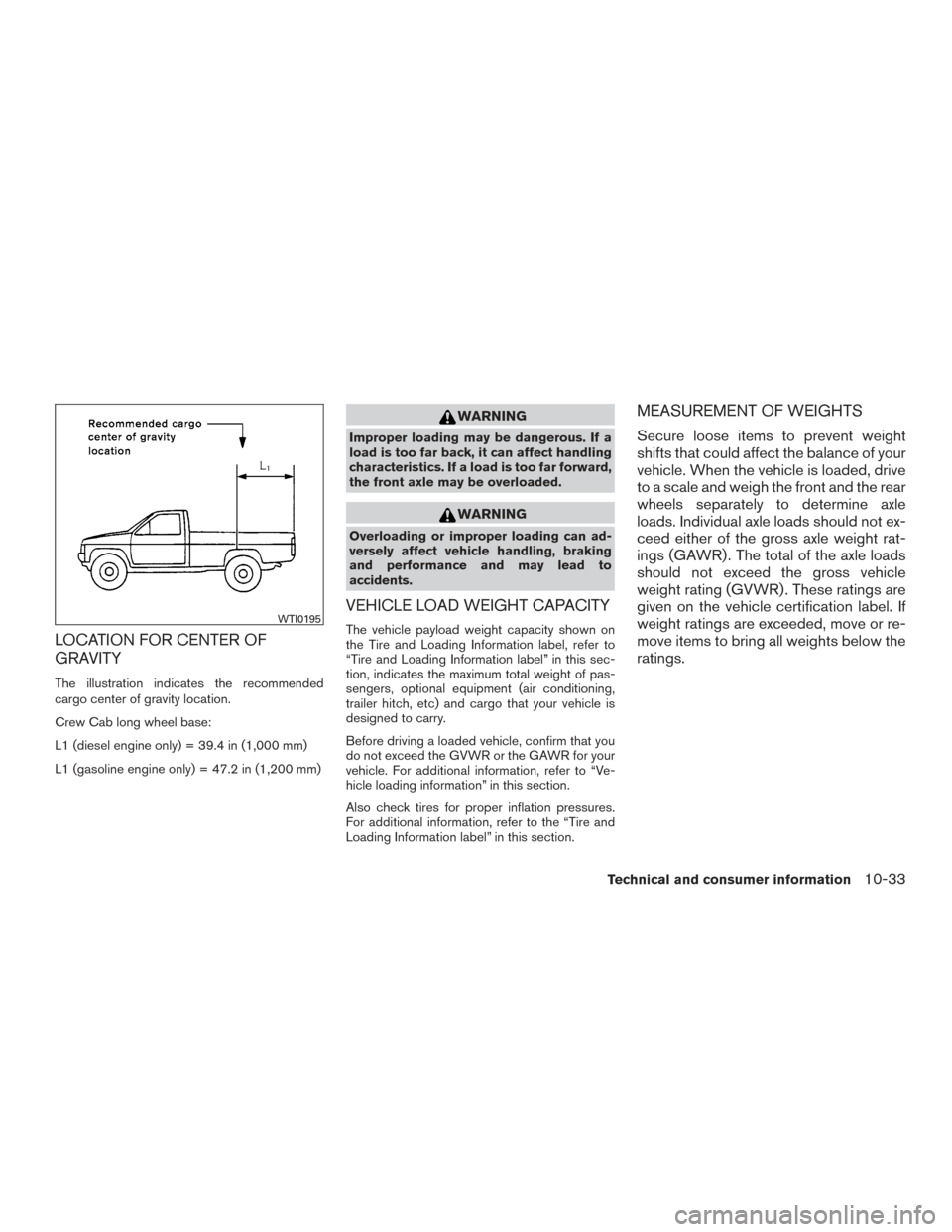
LOCATION FOR CENTER OF
GRAVITY
The illustration indicates the recommended
cargo center of gravity location.
Crew Cab long wheel base:
L1 (diesel engine only) = 39.4 in (1,000 mm)
L1 (gasoline engine only) = 47.2 in (1,200 mm)
WARNING
Improper loading may be dangerous. If a
load is too far back, it can affect handling
characteristics. If a load is too far forward,
the front axle may be overloaded.
WARNING
Overloading or improper loading can ad-
versely affect vehicle handling, braking
and performance and may lead to
accidents.
VEHICLE LOAD WEIGHT CAPACITY
The vehicle payload weight capacity shown on
the Tire and Loading Information label, refer to
“Tire and Loading Information label” in this sec-
tion, indicates the maximum total weight of pas-
sengers, optional equipment (air conditioning,
trailer hitch, etc) and cargo that your vehicle is
designed to carry.
Before driving a loaded vehicle, confirm that you
do not exceed the GVWR or the GAWR for your
vehicle. For additional information, refer to “Ve-
hicle loading information” in this section.
Also check tires for proper inflation pressures.
For additional information, refer to the “Tire and
Loading Information label” in this section.
MEASUREMENT OF WEIGHTS
Secure loose items to prevent weight
shifts that could affect the balance of your
vehicle. When the vehicle is loaded, drive
to a scale and weigh the front and the rear
wheels separately to determine axle
loads. Individual axle loads should not ex-
ceed either of the gross axle weight rat-
ings (GAWR) . The total of the axle loads
should not exceed the gross vehicle
weight rating (GVWR) . These ratings are
given on the vehicle certification label. If
weight ratings are exceeded, move or re-
move items to bring all weights below the
ratings.
WTI0195
Technical and consumer information10-33