Page 447 of 671
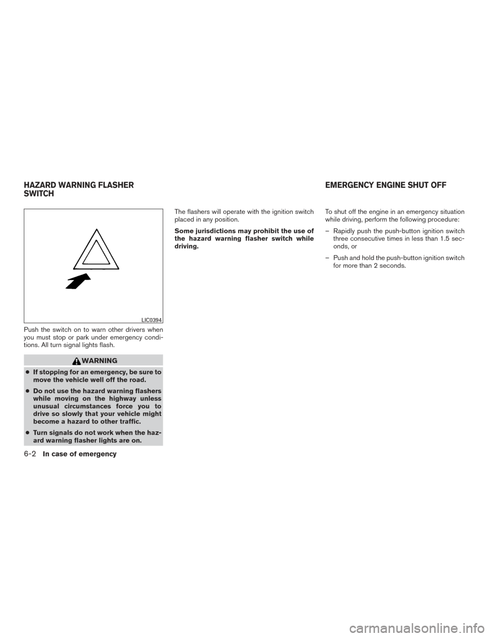
Push the switch on to warn other drivers when
you must stop or park under emergency condi-
tions. All turn signal lights flash.
WARNING
●If stopping for an emergency, be sure to
move the vehicle well off the road.
● Do not use the hazard warning flashers
while moving on the highway unless
unusual circumstances force you to
drive so slowly that your vehicle might
become a hazard to other traffic.
● Turn signals do not work when the haz-
ard warning flasher lights are on. The flashers will operate with the ignition switch
placed in any position.
Some jurisdictions may prohibit the use of
the hazard warning flasher switch while
driving.
To shut off the engine in an emergency situation
while driving, perform the following procedure:
– Rapidly push the push-button ignition switch
three consecutive times in less than 1.5 sec-
onds, or
– Push and hold the push-button ignition switch for more than 2 seconds.
LIC0394
HAZARD WARNING FLASHER
SWITCH EMERGENCY ENGINE SHUT OFF
6-2In case of emergency
Page 449 of 671
3. Park on a level surface and apply the parkingbrake. Move the shift lever to P (Park) .
4. Turn off the engine.
5. Raise the hood to warn other traffic and to signal professional road assistance person-
nel that you need assistance.
6. Have all passengers get out of the vehicle and stand in a safe place, away from traffic
and clear of the vehicle.
WARNING
●Make sure the parking brake is securely
applied and the shift lever is shifted into
P (Park) .
● Never change tires when the vehicle is
on a slope, ice or slippery areas. This is
hazardous.
● Never change tires if oncoming traffic is
close to your vehicle. Wait for profes-
sional road assistance.
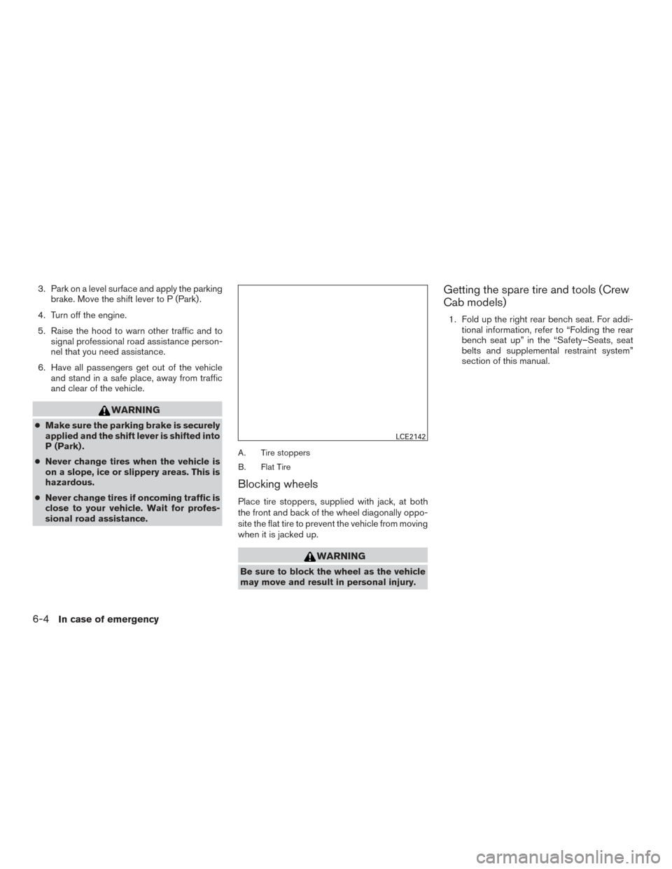
A. Tire stoppers
B. Flat Tire
Blocking wheels
Place tire stoppers, supplied with jack, at both
the front and back of the wheel diagonally oppo-
site the flat tire to prevent the vehicle from moving
when it is jacked up.
WARNING
Be sure to block the wheel as the vehicle
may move and result in personal injury.
Getting the spare tire and tools (Crew
Cab models)
1. Fold up the right rear bench seat. For addi- tional information, refer to “Folding the rear
bench seat up” in the “Safety–Seats, seat
belts and supplemental restraint system”
section of this manual.
LCE2142
6-4In case of emergency
Page 451 of 671
10. Securely store the flat tire beneath the ve-hicle, from where the full size spare was
removed.
11. To reinstall the jack and tool kit, reverse steps 1 through 5.
CAUTION
Be sure to center the spare tire suspend-
ing plate on the wheel and then lift the
spare tire.
Getting the spare tire and tools
(Single Cab models)
1. Move the front passenger seat to access thetools. For additional information about seat
functions, refer to “ Seats” in the “Safety-
–Seats, seat belts and supplemental re-
straint system” section of this manual. 2. Remove the lid from the tool storage com-
partment.
3. Release the straps
�A.
4. Remove the tire stopper bag
�B.
5. Remove the tool kit and jack
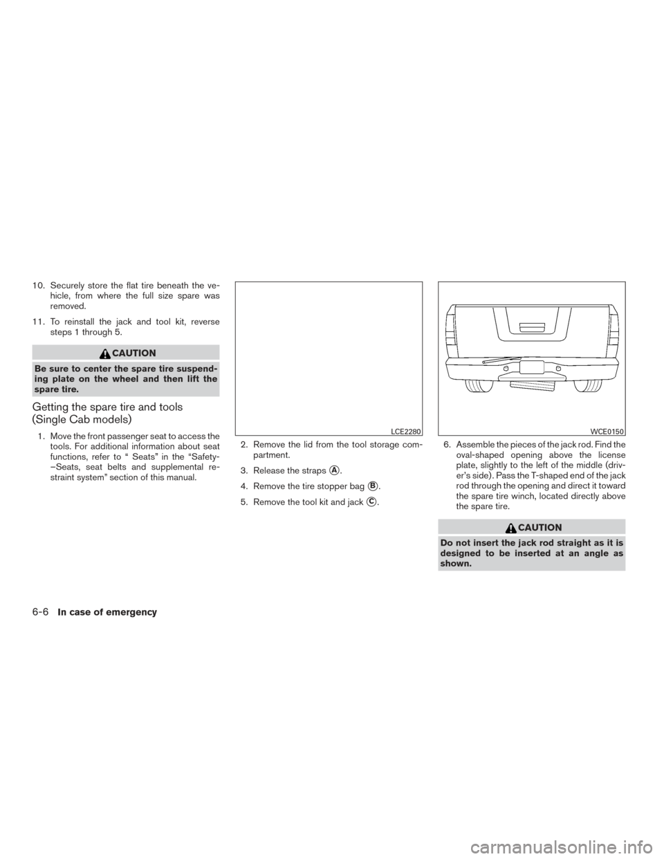
�C. 6. Assemble the pieces of the jack rod. Find the
oval-shaped opening above the license
plate, slightly to the left of the middle (driv-
er’s side) . Pass the T-shaped end of the jack
rod through the opening and direct it toward
the spare tire winch, located directly above
the spare tire.
CAUTION
Do not insert the jack rod straight as it is
designed to be inserted at an angle as
shown.
LCE2280WCE0150
6-6In case of emergency
Page 452 of 671
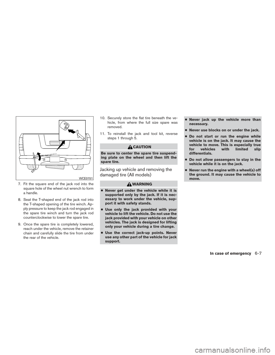
7. Fit the square end of the jack rod into thesquare hole of the wheel nut wrench to form
a handle.
8. Seat the T-shaped end of the jack rod into the T-shaped opening of the tire winch. Ap-
ply pressure to keep the jack rod engaged in
the spare tire winch and turn the jack rod
counterclockwise to lower the spare tire.
9. Once the spare tire is completely lowered, reach under the vehicle, remove the retainer
chain and carefully slide the tire from under
the rear of the vehicle. 10. Securely store the flat tire beneath the ve-
hicle, from where the full size spare was
removed.
11. To reinstall the jack and tool kit, reverse steps 1 through 5.
CAUTION
Be sure to center the spare tire suspend-
ing plate on the wheel and then lift the
spare tire.
Jacking up vehicle and removing the
damaged tire (All models)
WARNING
●Never get under the vehicle while it is
supported only by the jack. If it is nec-
essary to work under the vehicle, sup-
port it with safety stands.
● Use only the jack provided with your
vehicle to lift the vehicle. Do not use the
jack provided with your vehicle on other
vehicles. The jack is designed for lifting
only your vehicle during a tire change.
● Use the correct jack-up points. Never
use any other part of the vehicle for jack
support. ●
Never jack up the vehicle more than
necessary.
● Never use blocks on or under the jack.
● Do not start or run the engine while
vehicle is on the jack. It may cause the
vehicle to move. This is especially true
for vehicles with limited slip
differentials.
● Do not allow passengers to stay in the
vehicle while it is on the jack.
● Never run the engine with a wheel(s) off
the ground. It may cause the vehicle to
move.
WCE0151
In case of emergency6-7
Page 454 of 671
3. Install the assembled jack rod into the jackas shown.
4. To lift the vehicle, securely hold the jack lever and rod. Carefully raise the vehicle until the
tire clears the ground. 5. Remove the wheel nuts and then remove the
tire.
Installing the spare tire
The spare tire is designed for emergency
use. For additional information, refer to
“Wheels and tires” in the “Do-it-yourself”
section of this manual.
1. Clean any mud or dirt from the surface be- tween the wheel and hub.
2. Carefully put the spare tire on and tighten the wheel nuts finger tight.
3. With the wheel nut wrench, tighten wheel nuts alternately and evenly in the sequence
illustrated (
�1,�2,�3,�4,�5,�6) until they
are tight.
LCE0087
WCE0063
In case of emergency6-9
Page 455 of 671
4. Lower the vehicle slowly until the tiretouches the ground. Then, with the wheel
nut wrench, tighten the wheel nuts securely
in the sequence illustrated
(
�1,�2,�3,�4,�5,�6) . Lower the vehicle
completely.
WARNING
● Incorrect wheel nuts or improperly
tightened wheel nuts can cause the
wheel to become loose or come off.
This could cause an accident.
● Do not use oil or grease on the wheel
studs or nuts. This could cause the nuts
to become loose.
● Retighten the wheel nuts when the ve-
hicle has been driven for 600 miles
(1,000 km) (also in cases of a flat tire,
etc.) .
As soon as possible, tighten the wheel nuts
to the specified torque with a torque
wrench.
Wheel nut tightening torque:
Non-XD models: 98 ft-lb (133 N·m) XD models:
131 ft-lb (177 N·m)
The wheel nuts must be kept tightened to
specification at all times. It is recom-
mended that wheel nuts be tightened to
specifications at each lubrication interval.
Adjust tire pressure to the COLD pressure.
COLD pressure: After vehicle has been
parked for 3 hours or more or driven less
than 1 mi. (1.6 km) .
COLD tire pressures are shown on the Tire
and Loading Information label affixed to
the driver side center pillar.
After adjusting tire pressure to the COLD
tire pressure, the display(if so equipped) of
the tire pressure information may show
higher pressure than the COLD tire pres-
sure after the vehicle has been driven more
than 1 mi. (1.6 km) . This is because the tire
pressure increases as the tire temperature
rises. This does not indicate a system mal-
function. 5. Securely store the flat tire, tools and jacking equipment in the vehicle. For additional in-
formation about storing the flat tire, refer to
the “Getting the spare tire and tools” in this
section.
WARNING
●Always make sure that the spare tire
and jacking equipment are properly se-
cured after use. Such items can become
dangerous projectiles in an accident or
sudden stop.
● The spare tire is designed for emer-
gency use. For additional information,
refer to “Wheels and tires” in the “Do-
it-yourself” section of this manual.
6-10In case of emergency
Page 460 of 671
Rear-Wheel Drive models
NISSAN recommends that your vehicle be towed
with the driving (rear) wheels off the ground or
place the vehicle on a flat bed truck as illustrated.
CAUTION
●Never tow automatic transmission
models with the rear wheels on the
ground or four wheels on the ground
(forward or backward) , as this may
cause serious and expensive damage to
the transmission. If it is necessary to
tow the vehicle with the front wheels
raised always use towing dollies under
the rear wheels.
● When towing automatic transmission
models with the front wheels on the
ground or on towing dollies:
– Place the ignition switch in the OFF position and secure the steering
wheel in a straight-ahead position
with a rope or similar device. Never
secure the steering wheel by placing
the ignition switch in the LOCK posi-
tion. This may cause damage to the
lock mechanism (if so equipped) .
When towing long distances or speeds in excess
of 60 mph (97 km/h), remove the propeller shaft
before towing to prevent damage to the transmis-
sion. It is recommended that you visit a NISSAN
dealer for more information.
LCE2140
In case of emergency6-15
Page 469 of 671
When installing Genuine NISSAN floor mats,
follow the installation instructions provided with
the mat and the following:1. Position the floor mat in the floorwell so that the floor mat grommet holes are aligned with
the hook(s) .
2. Secure the grommet holes into the hook(s) and ensure that the floor mat is properly
positioned.
3. Make sure the floor mat does not interfere with pedal operation. With the ignition in the
OFF position, the selector lever in the P
(Park) position (Automatic Transmission
models) or the shift lever in the N (Neutral)
position (Manual Transmission models) fully
apply and release all pedals. The floor mat
must not interfere with pedal operation or
prevent the pedal from returning to its nor-
mal position.
It is recommended that you visit a NISSAN dealer
for details about installing the floor mats in your
vehicle. The illustration shows the location of the floor mat
positioning hooks.
SEAT BELTS
The seat belts can be cleaned by wiping them
with a sponge dampened in a mild soap solution.
Allow the belts to dry completely in the shade
before using them. For additional information,
refer to “Seat belt maintenance” in the “Safety-
–Seats, seat belts and supplemental restraint
system” section of this manual.
WARNING
Do not allow wet seat belts to roll up in the
retractor. NEVER use bleach, dye or
chemical solvents to clean the seat belts,
since these materials may severely
weaken the seat belt webbing.
Positioning hooks
LAI2039
7-6Appearance and care