2017 NISSAN QUEST wheel size
[x] Cancel search: wheel sizePage 67 of 520
1-48Safety — Seats, seat belts and supplemental restraint system
SSS0676
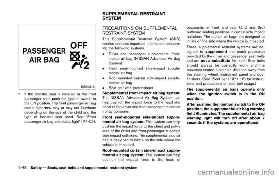
7. If the booster seat is installed in the frontpassenger seat, push the ignition switch to
the ON position. The front passenger air bag
status light
may or may not illuminate
depending on the size of the child and the
type of booster seat used. See “Front
passenger air bag and status light” (P.1-55) .
PRECAUTIONS ON SUPPLEMENTAL
RESTRAINT SYSTEM
This Supplemental Restraint System (SRS)
section contains important information concern-
ing the following systems.
. Driver and passenger supplemental front-
impact air bag (NISSAN Advanced Air Bag
System)
. Front seat-mounted side-impact supple-
mental air bag
. Roof-mounted curtain side-impact supple-
mental air bag
. Seat belt with pretensioner
Supplemental front-impact air bag system:
The NISSAN Advanced Air Bag System can
help cushion the impact force to the head and
chest of the driver and front passenger in certain
frontal collisions.
Front seat-mounted side-impact supple-
mental air bag system: This system can help
cushion the impact force to the chest and pelvis
area of the driver and front passenger in certain
side impact collisions. The supplemental side air
bag is designed to inflate on the side where the
vehicle is impacted.
Roof-mounted curtain side-impact supple-
mental air bag system: This system can help
cushion the impact force to the head of occupants in front and rear (2nd and 3rd)
outboard seating positions in certain side impact
collisions. The curtain air bags are designed to
inflate on the side where the vehicle is impacted.
These supplemental restraint systems are de-
signed to
supplement the crash protection
provided by the driver and passenger seat belts
and are not a substitute for them. Seat belts
should always be correctly worn and the
occupant seated a suitable distance away from
the steering wheel, instrument panel and door
finishers. (See “Seat belts” (P.1-15) for instruc-
tions and precautions on seat belt usage.)
The supplemental air bags operate only
when the ignition switch is in the ON
position.
After pushing the ignition switch to the ON
position, the supplemental air bag warning
light illuminates. The supplemental air bag
warning light will turn off after about 7
seconds if the systems are operational.
SUPPLEMENTAL RESTRAINT
SYSTEM
Page 102 of 520
shown on the Tire and Loading
Information label to turn the low
tire pressure warning light OFF. If
the light still illuminates while driv-
ing after adjusting the tire pressure,
a tire may be flat or the TPMS may
be malfunctioning. If you have a flat
tire, replace it with a spare tire as
soon as possible. If no tire is flat
and all tires are properly inflated, it
is recommended you consult a
NISSAN dealer.
. Since the spare tire is not equipped
with the TPMS, when a spare tire is
mounted or a wheel is replaced, the
TPMS will not function and the low
tire pressure warning light will flash
for approximately 1 minute. The
light will remain on after 1 minute.
Have your tires replaced and/or
TPMS system reset as soon as
possible. It is recommended you
visit a NISSAN dealer for these
services.
. Replacing tires with those not ori-
ginally specified by NISSAN could
affect the proper operation of the
TPMS.CAUTION
.The TPMS is not a substitute for the
regular tire pressure check. Be sure
to check the tire pressure regularly.
. If the vehicle is being driven at
speeds of less than 16 MPH (25
km/h) , the TPMS may not operate
correctly.
. Be sure to correctly install the
specified size of tires to the four
wheels.
Master warning light
When the ignition switch is in the ON position,
the master warning light illuminates if any of the
following are displayed on the vehicle informa-
tion display:
.No key warning
. Low fuel warning
. Low washer fluid warning
. Parking brake release warning
. Door/liftgate open warning
. Loose fuel cap warning
. Check tire pressure warning .
Extended storage fuse warning
See “Vehicle information display” (P.2-19) .
Seat belt warning light and chime
The light and chime remind you to fasten seat
belts. The light illuminates whenever the ignition
switch is pushed to the ON position, and will
remain illuminated until the driver’s seat belt is
fastened. At the same time, the chime will sound
for approximately 6 seconds unless the driver’s
seat belt is securely fastened.
The seat belt warning light for the front
passenger will illuminate if the seat belt is not
fastened when the front passenger’s seat is
occupied. For approximately 5 seconds after the
ignition switch is in the ON position, the system
does not activate the warning light for the front
passenger.
See “Seat belts” (P.1-15) for precautions on
seat belt usage.
Supplemental air bag warning light
After pushing the ignition switch to the ON
position, the supplemental air bag warning light
will illuminate. The supplemental air bag warning
light will turn off after about 7 seconds if the
supplemental front air bag and supplemental
side air bag, curtain air bag systems and/or
pretensioner seat belt are operational.
Instruments and controls2-15
Page 217 of 520
4-28Monitor, heater, air conditioner, audio, phone and voice recognition systems
course.
HOW TO PARK WITH PREDICTIVE
COURSE LINES (models with center
multi-function control panel)
WARNING
.If the tires are replaced with differ-
ent sized tires, the predictive course
line may not be displayed correctly.
. On a snow-covered or slippery road,
there may be a difference between
the predictive course line and the
actual course line.
. The displayed lines will appear
slightly off to the right because the
rearview camera is not installed in
the rear center of the vehicle.
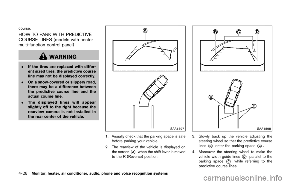
SAA1897
1. Visually check that the parking space is safe
before parking your vehicle.
2. The rearview of the vehicle is displayed on the screen
*Awhen the shift lever is moved
to the R (Reverse) position.
SAA1898
3. Slowly back up the vehicle adjusting the steering wheel so that the predictive course
lines
*Benter the parking space*C.
4. Maneuver the steering wheel to make the vehicle width guide lines
*Dparallel to the
parking space
*Cwhile referring to the
predictive course lines.
Page 222 of 520
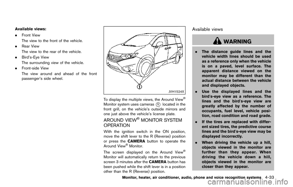
Available views:
.Front View
The view to the front of the vehicle.
. Rear View
The view to the rear of the vehicle.
. Bird’s-Eye View
The surrounding view of the vehicle.
. Front-side View
The view around and ahead of the front
passenger’s side wheel.
JVH1524X
To display the multiple views, the Around View�Š
Monitor system uses cameras*1located in the
front grill, on the vehicle’s outside mirrors and
one just above the vehicle’s license plate.
AROUND VIEW�ŠMONITOR SYSTEM
OPERATION
With the ignition switch in the ON position,
move the shift lever to the R (Reverse) position
or press the CAMERAbutton to operate the
Around View
�ŠMonitor.
The screen displayed on the Around View�Š
Monitor will automatically return to the previous
screen 3 minutes after the CAMERAbutton has
been pushed while the shift lever is in a position
other than the R (Reverse) position.
Available views
WARNING
. The distance guide lines and the
vehicle width lines should be used
as a reference only when the vehicle
is on a paved, level surface. The
apparent distance viewed on the
monitor may be different than the
actual distance between the vehicle
and displayed objects.
. Use the displayed lines and the
bird’s-eye view as a reference. The
lines and the bird’s-eye view are
greatly affected by the number of
occupants, fuel level, vehicle posi-
tion, road condition and road grade.
. If the tires are replaced with differ-
ent sized tires, the predictive course
lines and the bird’s-eye view may be
displayed incorrectly.
. When driving the vehicle up a hill,
objects viewed in the monitor are
further than they appear. When
driving the vehicle down a hill,
objects viewed in the monitor are
closer than they appear.
Monitor, heater, air conditioner, audio, phone and voice recognition systems4-33
Page 400 of 520
ing or downshifting. Abrupt braking
or accelerating could cause the
wheels to skid and result in an
accident.
. If the engine is not running or is
turned off while driving, the power
assist for the brakes will not work.
Braking will be harder.
Wet brakes
When the vehicle is washed or driven through
water, the brakes may get wet. As a result, your
braking distance will be longer and the vehicle
may pull to one side during braking.
To dry brakes, drive the vehicle at a safe speed
while lightly tapping the brake pedal to heat-up
the brakes. Do this until the brakes return to
normal. Avoid driving the vehicle at high speeds
until the brakes function correctly.
PARKING BRAKE BREAK-IN
Break in the parking brake shoes whenever the
stopping effect of the parking brake is weakened
or whenever the parking brake shoes and/or
drums/rotors are replaced, in order to assure the
best braking performance.
This procedure is described in the vehicle
service manual. It is recommended you visit a
NISSAN dealer for this service.
ANTI-LOCK BRAKING SYSTEM (ABS)
WARNING
.The Anti-lock Braking System (ABS)
is a sophisticated device, but it
cannot prevent accidents resulting
from careless or dangerous driving
techniques. It can help maintain
vehicle control during braking on
slippery surfaces. Remember that
stopping distances on slippery sur-
faces will be longer than on normal
surfaces even with ABS. Stopping
distances may also be longer on
rough, gravel or snow covered
roads, or if you are using tire chains.
Always maintain a safe distance
from the vehicle in front of you.
Ultimately, the driver is responsible
for safety.
. Tire type and condition may also
affect braking effectiveness.
— When replacing tires, install the
specified size of tires on all four
wheels.
— When installing a spare tire, make sure that it is the proper
size and type as specified on the Tire and Loading Information
label. See
“Tire and Loading
Information label” (P.10-10) .
— For detailed information, see “Wheels and tires” (P.8-27) .
The Anti-lock Braking System (ABS) controls
the brakes so the wheels do not lock during hard
braking or when braking on slippery surfaces.
The system detects the rotation speed at each
wheel and varies the brake fluid pressure to
prevent each wheel from locking and sliding. By
preventing each wheel from locking, the system
helps the driver maintain steering control and
helps to minimize swerving and spinning on
slippery surfaces.
Using the system
Depress the brake pedal and hold it down.
Depress the brake pedal with firm steady
pressure, but do not pump the brakes. The
ABS will operate to prevent the wheels from
locking up. Steer the vehicle to avoid obstacles.
WARNING
Do not pump the brake pedal. Doing so
may result in increased stopping dis-
tances.
Starting and driving5-31
Page 403 of 520
5-34Starting and driving
ing lightmay illuminate.
. The VDC system is not a substitute
for winter tires or tire chains on a
snow covered road.FREEING A FROZEN DOOR LOCK
To prevent a door lock from freezing, apply
deicer through the key hole. If the lock becomes
frozen, heat the key before inserting it into the
key hole or use the remote keyless entry key fob.
ANTI-FREEZE
In the winter when it is anticipated that the
outside temperature will drop below 328F(0 8C) ,
check the anti-freeze to assure proper winter
protection. For additional information, see “En-
gine cooling system” (P.8-4) .
BATTERY
If the battery is not fully charged during
extremely cold weather conditions, the battery
fluid may freeze and damage the battery. To
maintain maximum efficiency, the battery should
be checked regularly. For additional information,
see “Battery” (P.8-10) .
DRAINING OF COOLANT WATER
If the vehicle is to be left outside without anti-
freeze, drain the cooling system, including the
engine block. Refill before operating the vehicle.
For details, see “Engine cooling system” (P.8-4) .
TIRE EQUIPMENT
SUMMER tires have a tread designed to provide
superior performance on dry pavement. How-
ever, the performance of these tires will be
substantially reduced in snowy and icy condi-
tions. If you operate your vehicle on snowy or icy
roads, NISSAN recommends the use of MUD &
SNOW or ALL SEASON tires on all four wheels.
It is recommended you consult a NISSAN dealer
for the tire type, size, speed rating and
availability information.
For additional traction on icy roads, studded
tires may be used. However, some U.S. states
and Canadian provinces prohibit their use.
Check local, state and provincial laws before
installing studded tires.
Skid and traction capabilities of studded
snow tires, on wet or dry surfaces, may be
poorer than that of non-studded snow
tires.
Tire chains may be used. For details, see “Tire
chains” (P.8-33) .
SPECIAL WINTER EQUIPMENT
It is recommended that the following items be
carried in the vehicle during winter:
. A scraper and stiff-bristled brush to remove
ice and snow from the windows and wiper
blades.
COLD WEATHER DRIVING
Page 414 of 520
4. Lower the vehicle slowly until the tiretouches the ground. Then, with the wheel
nut wrench, tighten the wheel nuts securely
in the sequence illustrated. Lower the
vehicle completely.
5. Securely store the flat tire, jack and tools in the vehicle.
WARNING
.Incorrect wheel nuts or improperly
tightened wheel nuts can cause the
wheel to become loose or come off.
This could cause an accident.
. Do not use oil or grease on the
wheel studs or nuts. This could
cause the nuts to become loose.
. Retighten the wheel nuts when the
vehicle has been driven for 600
miles (1,000 km) (also in cases of a
flat tire, etc.) .
.As soon as possible, tighten the
wheel nuts to the specified torque
with a torque wrench.
Wheel nut tightening torque: 80 ft-lb (108 N·m)
The wheel nuts must be kept tigh- tened to specification at all times. It
is recommended that wheel nuts be
tightened to specifications at each
lubrication interval.
.Adjust tire pressure to the COLD
pressure.
COLD pressure:
After the vehicle has been parked
for three hours or more or driven
less than 1 mile (1.6 km) .
COLD tire pressures are shown on
the Tire and Loading Information
label affixed to the driver side center
pillar.
Stowing the spare tire and the tools
Securely store the spare tire, jack and tools in
their original location.
WARNING
. Always make sure that the spare tire
and jacking equipment are properly
secured after use. Such items can
become dangerous projectiles in an
accident or sudden stop.
. The T-type spare tire and small size
spare tire are designed for emer- gency use. See specific instructions
under the heading
“Wheels and
tires” (P.8-27) .
In case of emergency6-9
Page 460 of 520
SDI1575
Example
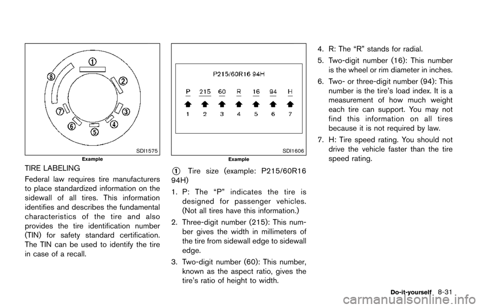
TIRE LABELING
Federal law requires tire manufacturers
to place standardized information on the
sidewall of all tires. This information
identifies and describes the fundamental
characteristics of the tire and also
provides the tire identification number
(TIN) for safety standard certification.
The TIN can be used to identify the tire
in case of a recall.
SDI1606
Example
*1Tire size (example: P215/60R16
94H)
1. P: The “P” indicates the tire is designed for passenger vehicles.
(Not all tires have this information.)
2. Three-digit number (215): This num- ber gives the width in millimeters of
the tire from sidewall edge to sidewall
edge.
3. Two-digit number (60): This number, known as the aspect ratio, gives the
tire’s ratio of height to width. 4. R: The “R” stands for radial.
5. Two-digit number (16): This number
is the wheel or rim diameter in inches.
6. Two- or three-digit number (94): This number is the tire’s load index. It is a
measurement of how much weight
each tire can support. You may not
find this information on all tires
because it is not required by law.
7. H: Tire speed rating. You should not drive the vehicle faster than the tire
speed rating.
Do-it-yourself8-31