2017 NISSAN QUEST tow
[x] Cancel search: towPage 28 of 520
SSS1163
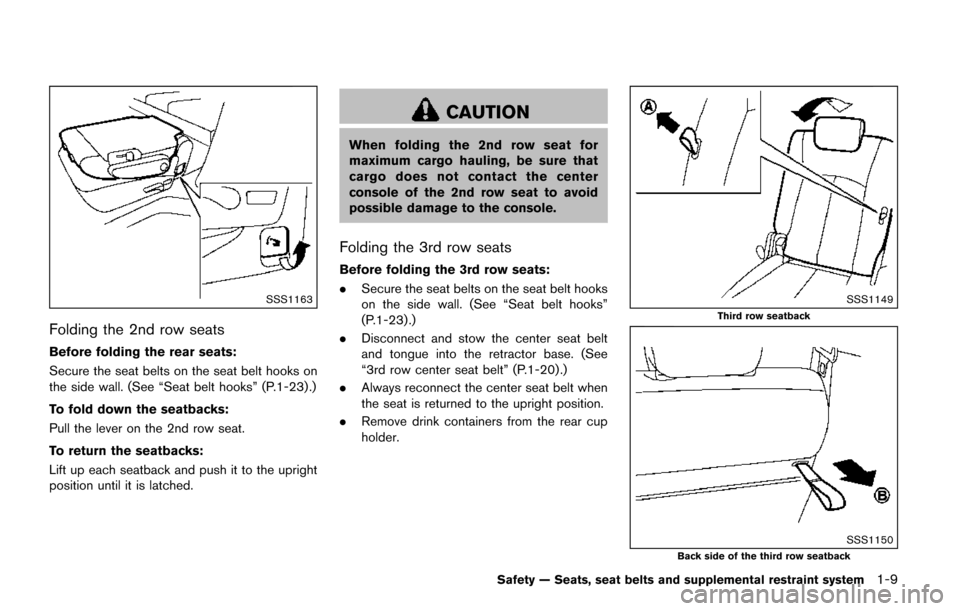
Folding the 2nd row seats
Before folding the rear seats:
Secure the seat belts on the seat belt hooks on
the side wall. (See “Seat belt hooks” (P.1-23) .)
To fold down the seatbacks:
Pull the lever on the 2nd row seat.
To return the seatbacks:
Lift up each seatback and push it to the upright
position until it is latched.
CAUTION
When folding the 2nd row seat for
maximum cargo hauling, be sure that
cargo does not contact the center
console of the 2nd row seat to avoid
possible damage to the console.
Folding the 3rd row seats
Before folding the 3rd row seats:
.Secure the seat belts on the seat belt hooks
on the side wall. (See “Seat belt hooks”
(P.1-23) .)
. Disconnect and stow the center seat belt
and tongue into the retractor base. (See
“3rd row center seat belt” (P.1-20) .)
. Always reconnect the center seat belt when
the seat is returned to the upright position.
. Remove drink containers from the rear cup
holder.
SSS1149
Third row seatback
SSS1150Back side of the third row seatback
Safety — Seats, seat belts and supplemental restraint system1-9
Page 38 of 520
SSS0292
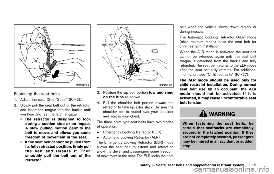
Fastening the seat belts
1. Adjust the seat. (See “Seats” (P.1-2) .)
2. Slowly pull the seat belt out of the retractorand insert the tongue into the buckle until
you hear and feel the latch engage.
.The retractor is designed to lockduring a sudden stop or on impact.
A slow pulling motion permits the
belt to move, and allows you some
freedom of movement in the seat.
.If the seat belt cannot be pulled from
its fully retracted position, firmly pull
the belt and release it. Then
smoothly pull the belt out of the
retractor.
SSS0290
3. Position the lap belt portion low and snug
on the hips as shown.
4. Pull the shoulder belt portion toward the retractor to take up extra slack. Be sure the
shoulder belt is routed over your shoulder
and across your chest.
The three-point type seat belts have two modes
of operation:
. Emergency Locking Retractor (ELR)
. Automatic Locking Retractor (ALR)
The Emergency Locking Retractor (ELR) mode
allows the seat belt to extend and retract to
allow the driver and passengers some freedom
of movement in the seat. The ELR locks the seat belt when the vehicle slows down rapidly or
during impacts.
The Automatic Locking Retractor (ALR) mode
(child restraint mode) locks the seat belt for
child restraint installation.
When the ALR mode is activated the seat belt
cannot be extended again until the seat belt
tongue is detached from the buckle and fully
retracted. The seat belt returns to the ELR mode
after the seat belt fully retracts. For additional
information, see “Child restraints” (P.1-27) .
The ALR mode should be used only for
child restraint installation. During normal
seat belt use by an occupant, the ALR
mode should not be activated. If it is
activated, it may cause uncomfortable seat
belt tension.
WARNING
When fastening the seat belts, be
certain that seatbacks are completely
secured in the latched position. If they
are not completely secured, passengers
may be injured in an accident or sudden
stop.
Safety — Seats, seat belts and supplemental restraint system1-19
Page 40 of 520
SSS0241
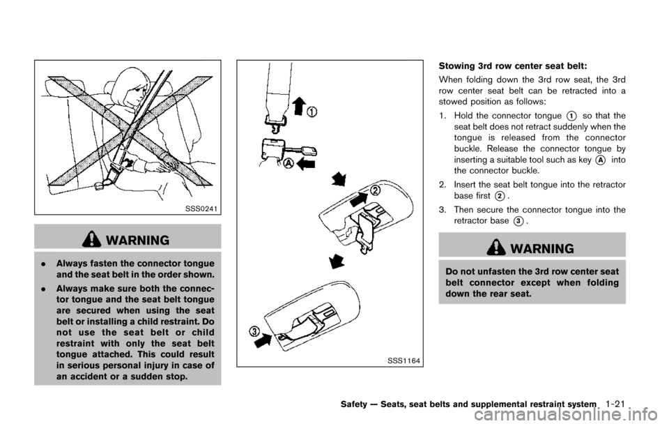
WARNING
.Always fasten the connector tongue
and the seat belt in the order shown.
. Always make sure both the connec-
tor tongue and the seat belt tongue
are secured when using the seat
belt or installing a child restraint. Do
not use the seat belt or child
restraint with only the seat belt
tongue attached. This could result
in serious personal injury in case of
an accident or a sudden stop.
SSS1164
Stowing 3rd row center seat belt:
When folding down the 3rd row seat, the 3rd
row center seat belt can be retracted into a
stowed position as follows:
1. Hold the connector tongue
*1so that the
seat belt does not retract suddenly when the
tongue is released from the connector
buckle. Release the connector tongue by
inserting a suitable tool such as key
*Ainto
the connector buckle.
2. Insert the seat belt tongue into the retractor base first
*2.
3. Then secure the connector tongue into the retractor base
*3.
WARNING
Do not unfasten the 3rd row center seat
belt connector except when folding
down the rear seat.
Safety — Seats, seat belts and supplemental restraint system1-21
Page 66 of 520
SSS0640
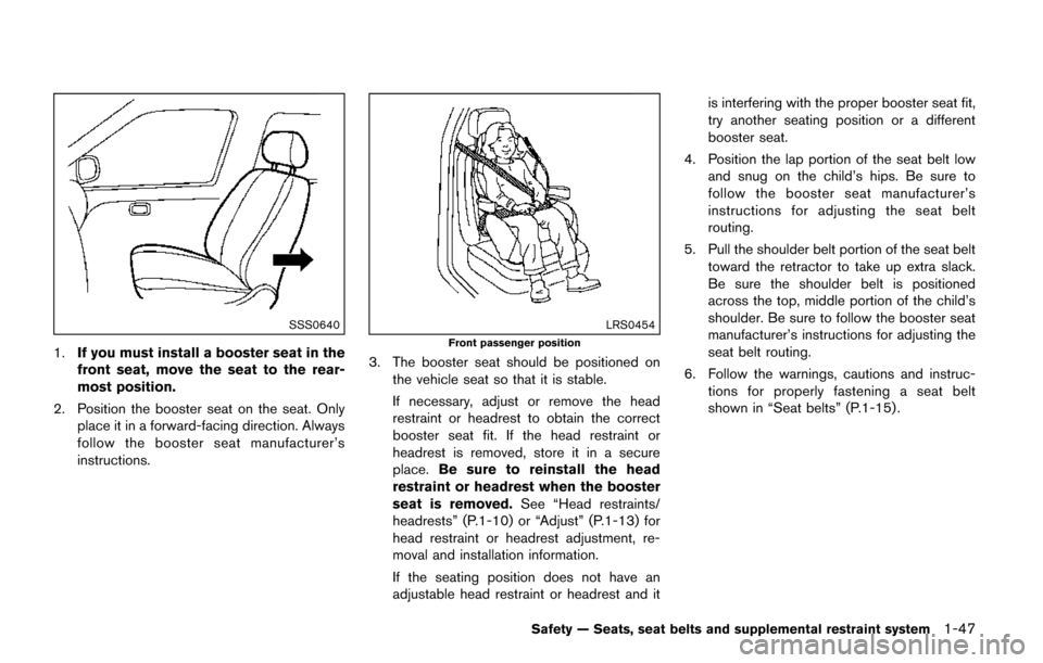
1.If you must install a booster seat in the
front seat, move the seat to the rear-
most position.
2. Position the booster seat on the seat. Only place it in a forward-facing direction. Always
follow the booster seat manufacturer’s
instructions.
LRS0454
Front passenger position
3. The booster seat should be positioned onthe vehicle seat so that it is stable.
If necessary, adjust or remove the head
restraint or headrest to obtain the correct
booster seat fit. If the head restraint or
headrest is removed, store it in a secure
place. Be sure to reinstall the head
restraint or headrest when the booster
seat is removed. See “Head restraints/
headrests” (P.1-10) or “Adjust” (P.1-13) for
head restraint or headrest adjustment, re-
moval and installation information.
If the seating position does not have an
adjustable head restraint or headrest and it is interfering with the proper booster seat fit,
try another seating position or a different
booster seat.
4. Position the lap portion of the seat belt low and snug on the child’s hips. Be sure to
follow the booster seat manufacturer’s
instructions for adjusting the seat belt
routing.
5. Pull the shoulder belt portion of the seat belt toward the retractor to take up extra slack.
Be sure the shoulder belt is positioned
across the top, middle portion of the child’s
shoulder. Be sure to follow the booster seat
manufacturer’s instructions for adjusting the
seat belt routing.
6. Follow the warnings, cautions and instruc- tions for properly fastening a seat belt
shown in “Seat belts” (P.1-15) .
Safety — Seats, seat belts and supplemental restraint system1-47
Page 79 of 520
1-60Safety — Seats, seat belts and supplemental restraint system
personal injury.
. Immediately after inflation, several
front air bag system components
will be hot. Do not touch them; you
may severely burn yourself.
. No unauthorized changes should be
made to any components or wiring
of the supplemental air bag system.
This is to prevent accidental infla-
tion of the supplemental air bag or
damage to the supplemental air bag
system.
. Do not make unauthorized changes
to your vehicle’s electrical system,
suspension system or front end
structure. This could affect proper
operation of the front air bag sys-
tem.
. Tampering with the air bag system
may result in serious personal in-
jury. Tampering includes changes to
the steering wheel and the instru-
ment panel assembly by placing
material over the steering wheel
pad and above the instrument panel
or by installing additional trim ma-
terial around the air bag system. .
Removing or modifying the front
passenger seat may affect the func-
tion of the air bag system and result
in serious personal injury.
. Modifying or tampering with the
front passenger seat may result in
serious personal injury. For exam-
ple, do not change the front seats by
placing material on the seat cushion
or by installing additional trim ma-
terial, such as seat covers, on the
seat that is not specifically designed
to assure proper air bag operation.
Additionally, do not stow any ob-
jects under the front passenger seat
or the seat cushion and seatback.
Such objects may interfere with the
proper operation of the occupant
classification sensors.
. No unauthorized changes should be
made to any components or wiring
of the seat belt system. This may
affect the front air bag system.
Tampering with the seat belt system
may result in serious personal in-
jury.
. It is recommended you visit a
NISSAN dealer for work on and
around the front air bag. It is also recommended you visit a NISSAN
dealer for installation of electrical
equipment. The Supplemental Re-
straint System (SRS) wiring har-
nesses* should not be modified or
disconnected. Unauthorized electri-
cal test equipment and probing
devices should not be used on the
air bag system.
. A cracked windshield should be
replaced immediately by a qualified
repair facility. A cracked windshield
could affect the function of the
supplemental air bag system.
* The SRS wiring harness connectors are
yellow and orange for easy identification.
When selling your vehicle, we request that you
inform the buyer about the front air bag system
and guide the buyer to the appropriate sections
in this Owner’s Manual.
Page 92 of 520
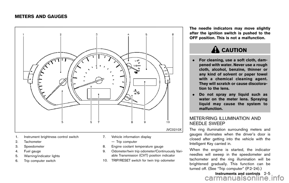
JVC0210X
1. Instrument brightness control switch
2. Tachometer
3. Speedometer
4. Fuel gauge
5. Warning/indicator lights
6. Trip computer switch7. Vehicle information display
— Trip computer
8. Engine coolant temperature gauge
9. Odometer/twin trip odometer/Continuously Vari- able Transmission (CVT) position indicator
10. TRIP/RESET switch for twin trip odometer
The needle indicators may move slightly
after the ignition switch is pushed to the
OFF position. This is not a malfunction.
CAUTION
. For cleaning, use a soft cloth, dam-
pened with water. Never use a rough
cloth, alcohol, benzine, thinner or
any kind of solvent or paper towel
with a chemical cleaning agent.
They will scratch or cause discolora-
tion to the lens.
. Do not spray any liquid such as
water on the meter lens. Spraying
liquid may cause the system to
malfunction.
METER/RING ILLUMINATION AND
NEEDLE SWEEP
The ring illumination surrounding meters and
gauges illuminates when the driver’s door is
closed after getting into the vehicle with the
Intelligent Key carried in.
When the engine is started, the indicator
needles will sweep in the speedometer and
tachometer and the ring illumination will be
brightened gradually. This function can be
turned off. (See “Trip computer” (P.2-24) .)
Instruments and controls2-5
METERS AND GAUGES
Page 97 of 520
2-10Instruments and controls
ZONE VARIATION CHANGE PROCE-
DURE
The difference between magnetic north and
geographical north is known as variance. In
some areas, this difference can sometimes be
great enough to cause false compass readings.
Follow these instructions to set the variance for
your particular location if this happens:
1. Push the
switch for more than 3
seconds. The current zone number will
appear in the display.
2. Find your current location and variance number on the zone map.
NOTE:
Use zone number 5 for Hawaii.
3. Push the
switch repeatedly until the
new zone number appears in the display,
then release the switch. After you release
the switch, the display will show a compass
direction within a few seconds.
.If the compass deviates from the correct indication soon after repeated adjust-
ment, have the compass checked. It is
recommended you visit a NISSAN dealer
for this service.
.The compass may not indicate the
correct compass point in tunnels or while
driving up or down a steep hill. (The compass returns to the correct com-
pass point when the vehicle moves to an
area where the geomagnetism is stabilized.)
CAUTION
.
Do not install a ski rack, antenna,
etc., which are attached to the
vehicle by means of a magnet. They
affect the operation of the compass.
. When cleaning the mirror, use a
paper towel or similar material
dampened with glass cleaner. Do
not spray glass cleaner directly on
the mirror as it may cause the liquid
cleaner to enter the mirror housing.
Page 100 of 520
“Anti-lock Braking System (ABS) warning light”
(P.2-12) .)
WARNING
.Your brake system may not be
working properly if the warning light
is on. Driving could be dangerous. If
you judge it to be safe, drive care-
fully to the nearest service station
for repairs. Otherwise, have your
vehicle towed because driving it
could be dangerous.
. Pressing the brake pedal with the
engine stopped and/or low brake
fluid level may increase your stop-
ping distance and braking will re-
quire greater pedal effort as well as
pedal travel.
. If the brake fluid level is below the
minimum or MIN mark on the brake
fluid reservoir, do not drive until the
brake system has been checked. It
is recommended you visit a NISSAN
dealer for this service.
Charge warning light
If the light comes on while the engine is running,
it may indicate the charging system is not
functioning properly. Turn the engine off and
check the alternator belt. If the belt is loose,
broken, missing or if the light remains on, have
your vehicle serviced immediately. It is recom-
mended you visit a NISSAN dealer for this
service.
CAUTION
Do not continue driving if the alternator
belt is loose, broken or missing.
Engine oil pressure warning light
This light warns of low engine oil pressure. If the
light flickers or comes on during normal driving,
pull off the road in a safe area, stop the engine
immediately and call a NISSAN dealer or other
authorized repair shop.
The engine oil pressure warning light is
not designed to indicate a low oil level.
Use the dipstick to check the oil level. (See
“Engine oil” (P.8-5).)
CAUTION
Running the engine with the engine oil
pressure warning light on could cause
serious damage to the engine almost
immediately. Such damage is not cov-
ered by warranty. Turn off the engine as
soon as it is safe to do so.
Hydraulic pump electric power
steering warning light
When the ignition switch is in the ON position,
the hydraulic pump electric power steering
warning light illuminates. After starting the
engine, the hydraulic pump electric power
steering warning light turns off. This indicates
that the electric power steering is operational.
If the hydraulic pump electric power steering
warning light illuminates while the engine is
running, it may indicate the hydraulic pump
electric power steering is not functioning prop-
erly and may need servicing. It is recommended
you have the hydraulic pump electric power
steering checked by a NISSAN dealer. (See
“Hydraulic pump electric power steering” (P.5-
30) .)
Instruments and controls2-13