2017 NISSAN QUEST lock
[x] Cancel search: lockPage 179 of 520
3-28Pre-driving checks and adjustments
Power open
When the liftgate is fully closed, the liftgate will
fully open automatically by:
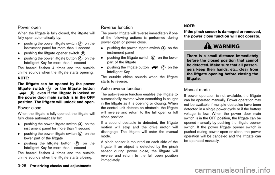
.pushing the power liftgate switch
*Aon the
instrument panel for more than 1 second
. pushing the liftgate opener switch
*B
.pushing the power liftgate button*Con the
Intelligent Key for more than 1 second
The hazard flashes 4 times and the outside
chime sounds when the liftgate starts opening.
NOTE:
The liftgate can be opened by the power
liftgate switch
*Aor the liftgate button
*Ceven if the liftgate is locked or
the power door main switch is in the OFF
position. The liftgate will unlock and open.
Power close
When the liftgate is fully opened, the liftgate will
fully close automatically by:
. pushing the power liftgate switch
*Aon the
instrument panel for more than 1 second
. pushing the power liftgate switch
*Don the
lower part of the liftgate
. pushing the liftgate button
*Con the
Intelligent Key for more than 1 second
The hazard flashes 4 times and the outside
chime sounds when the liftgate starts closing.
Reverse function
The power liftgate will reverse immediately if one
of the following actions is performed during
power open or power close.
. pushing the power liftgate switch
*Aon the
instrument panel
. pushing the liftgate switch
*Don the lower
part of the liftgate
. pushing the liftgate button
*Con the
Intelligent Key.
The outside chime sounds when the liftgate
starts to reverse.
Auto reverse function
The auto-reverse function enables the liftgate to
automatically reverse when something is caught
in the liftgate as it is opening or closing. When
the control unit detects an obstacle, the liftgate
will reverse and return to the full open or full
close position.
If a second obstacle is detected, the liftgate
motion will stop and the drive motor will
disengage. The liftgate will enter the manual
mode.
A pinch sensor is mounted on each side of the
liftgate. If an object is detected by the pinch
sensor during power close, the liftgate will
reverse and return to the full open position
immediately. NOTE:
If the pinch sensor is damaged or removed,
the power close function will not operate.
WARNING
There is a small distance immediately
before the closed position that cannot
be detected. Make sure that all passen-
gers keep their hands, etc., clear from
the liftgate opening before closing the
liftgate.
Manual mode
If power operation is not available, the liftgate
can be operated manually. Power operation may
not be available if multiple obstacles have been
detected in a single power cycle or if the battery
voltage is low. When the power door main
switch is in the OFF position, the liftgate can be
opened manually by pushing the liftgate opener
switch. If the power liftgate opener switch is
pushed during power open or close, the power
operation will be canceled and the liftgate can
be operated manually.
Page 182 of 520
— Always place the container onthe ground when filling.
— Do not use electronic devices when filling.
— Keep the pump nozzle in contact with the container while you are
filling it.
— Use only approved portable fuel containers for flammable liquid.
CAUTION
. If fuel is spilled on the vehicle body,
flush it away with water to avoid
paint damage.
. Insert the cap straight into the fuel-
filler tube, then tighten until the
fuel-filler cap clicks. Failure to tight-
en the fuel-filler cap properly may
cause the
malfunction indicator
light (MIL) to illuminate. If the
light illuminates because the fuel-
filler cap is loose or missing, tighten
or install the cap and continue to
drive the vehicle. The
light
should turn off after a few driving
trips. If the
light does not turn off after a few driving trips, have the
vehicle inspected. It is recom-
mended you visit a NISSAN dealer
for this service.
For additional information, see
“Malfunction Indicator Light (MIL)”
(P.2-17) .
. The LOOSE FUEL CAP warning will
appear if the fuel-filler cap is not
properly tightened. It may take a few
driving trips for the message to be
displayed. Failure to tighten the
fuel-filler cap properly after the
LOOSE FUEL CAP warning appears
may cause the
Malfunction
Indicator Light (MIL) to illuminate.
JVP0067X
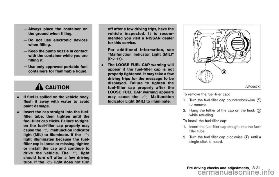
To remove the fuel-filler cap:
1. Turn the fuel-filler cap counterclockwise
*1
to remove.
2. Hang the tether of the cap on the hook
*3
while refueling.
To install the fuel-filler cap:
1. Insert the fuel-filler cap straight into the fuel- filler tube.
2. Turn the fuel-filler cap clockwise
*2until a
single click is heard.
Pre-driving checks and adjustments3-31
Page 183 of 520
3-32Pre-driving checks and adjustments
SPA2833
LOOSE FUEL CAP warning
The LOOSE FUEL CAP warning appears on the
vehicle information display when the fuel-filler
cap is not tightened correctly after the vehicle
has been refueled. It may take a few driving trips
for the message to be displayed. To turn off the
warning, perform the following steps:
1. Remove and install the fuel-filler cap as soonas possible. (See “Fuel-filler cap” (P.3-30) .)
2. Tighten the fuel-filler cap until it clicks.
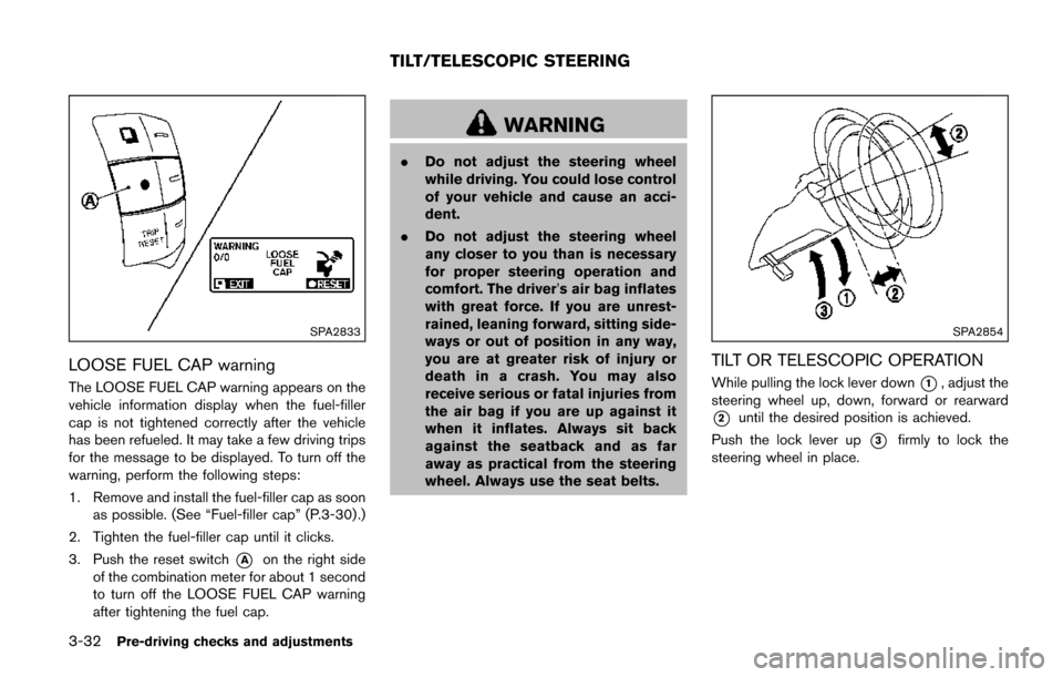
3. Push the reset switch
*Aon the right side
of the combination meter for about 1 second
to turn off the LOOSE FUEL CAP warning
after tightening the fuel cap.
WARNING
. Do not adjust the steering wheel
while driving. You could lose control
of your vehicle and cause an acci-
dent.
. Do not adjust the steering wheel
any closer to you than is necessary
for proper steering operation and
comfort. The driver’s air bag inflates
with great force. If you are unrest-
rained, leaning forward, sitting side-
ways or out of position in any way,
you are at greater risk of injury or
death in a crash. You may also
receive serious or fatal injuries from
the air bag if you are up against it
when it inflates. Always sit back
against the seatback and as far
away as practical from the steering
wheel. Always use the seat belts.
SPA2854
TILT OR TELESCOPIC OPERATION
While pulling the lock lever down*1, adjust the
steering wheel up, down, forward or rearward
*2until the desired position is achieved.
Push the lock lever up
*3firmly to lock the
steering wheel in place.
TILT/TELESCOPIC STEERING
Page 184 of 520
SIC3451
CAUTION
.Do not store the main sun visor
before storing the extension sun
visor.
. Do not pull the extension sun visor
forcedly downward.
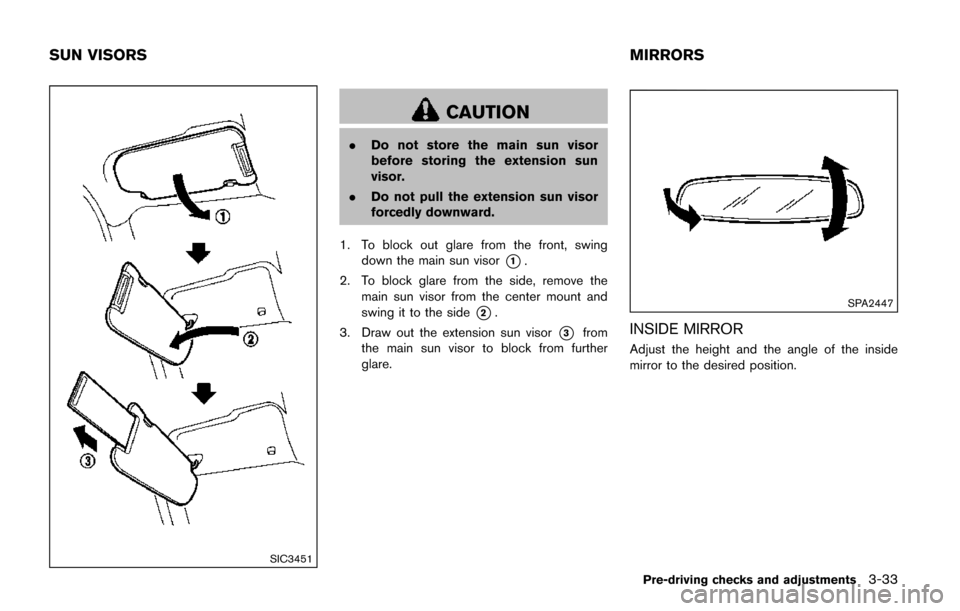
1. To block out glare from the front, swing down the main sun visor
*1.
2. To block glare from the side, remove the main sun visor from the center mount and
swing it to the side
*2.
3. Draw out the extension sun visor
*3from
the main sun visor to block from further
glare.
SPA2447
INSIDE MIRROR
Adjust the height and the angle of the inside
mirror to the desired position.
Pre-driving checks and adjustments3-33
SUN VISORS MIRRORS
Page 187 of 520
3-36Pre-driving checks and adjustments
SPA1829
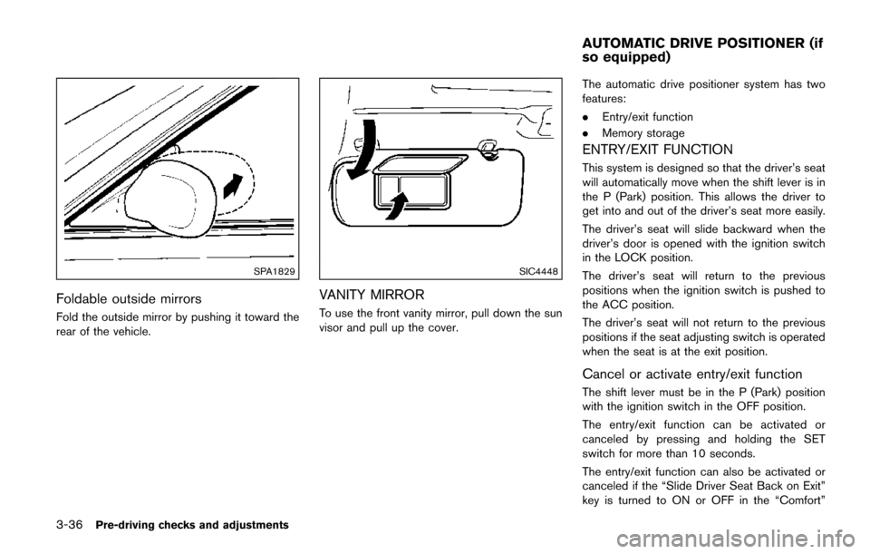
Foldable outside mirrors
Fold the outside mirror by pushing it toward the
rear of the vehicle.
SIC4448
VANITY MIRROR
To use the front vanity mirror, pull down the sun
visor and pull up the cover.The automatic drive positioner system has two
features:
.
Entry/exit function
. Memory storage
ENTRY/EXIT FUNCTION
This system is designed so that the driver’s seat
will automatically move when the shift lever is in
the P (Park) position. This allows the driver to
get into and out of the driver’s seat more easily.
The driver’s seat will slide backward when the
driver’s door is opened with the ignition switch
in the LOCK position.
The driver’s seat will return to the previous
positions when the ignition switch is pushed to
the ACC position.
The driver’s seat will not return to the previous
positions if the seat adjusting switch is operated
when the seat is at the exit position.
Cancel or activate entry/exit function
The shift lever must be in the P (Park) position
with the ignition switch in the OFF position.
The entry/exit function can be activated or
canceled by pressing and holding the SET
switch for more than 10 seconds.
The entry/exit function can also be activated or
canceled if the “Slide Driver Seat Back on Exit”
key is turned to ON or OFF in the “Comfort”
AUTOMATIC DRIVE POSITIONER (if
so equipped)
Page 188 of 520
settings. (See “Vehicle information and settings
(models with center multi-function control pa-
nel)” (P.4-10) .)
Initialize entry/exit function
If the battery cable is disconnected, or if the fuse
opens, the entry/exit function will not work
though this function was set on before. In such
a case, after connecting the battery or replacing
with a new fuse, open and close the driver’s
door more than two times after the ignition
switch is placed in the LOCK position from the
ON position. The entry/exit function will be
activated.
JVP0248X
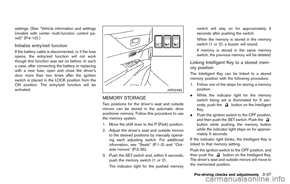
MEMORY STORAGE
Two positions for the driver’s seat and outside
mirrors can be stored in the automatic drive
positioner memory. Follow this procedure to use
the memory system.
1. Move the shift lever to the P (Park) position.
2. Adjust the driver’s seat and outside mirrorsto the desired positions by manually operat-
ing each adjusting switch. For additional
information, see “Seats” (P.1-2) and “Out-
side mirrors” (P.3-35) .
3. Push the SET switch and, within 5 seconds, push the memory switch (1 or 2) .
The indicator light for the pushed memory switch will stay on for approximately 5
seconds after pushing the switch.
When the memory is stored in the memory
switch (1 or 2) , a buzzer will sound.
If memory is stored in the same memory
switch, the previous memory will be deleted.
Linking Intelligent Key to a stored mem-
ory position
The Intelligent Key can be linked to a stored
memory position with the following procedure.
1. Follow one of the steps for storing a memory
position.
. While the indicator light for the memory
switch being set is illuminated for 5 sec-
onds, push the
button on the Intelligent
Key.
. Push the ignition switch to the OFF position,
and then push the SET switch. Push the
button while pushing the memory button
while the indicator light stays on for approxi-
mately 5 seconds.
If the indicator light blinks, the Intelligent Key is
linked to that memory setting.
Push the ignition switch to the OFF position, and
then push the
button on the Intelligent Key.
The driver’s seat and outside mirrors will move to
the memorized position.
Pre-driving checks and adjustments3-37
Page 208 of 520
Brightness/Contrast/Background Color:
To adjust the brightness, contrast and back-
ground color of the screen, select the appro-
priate “Brightness”, “Contrast” or “Background
Color” key and push the ENTER button.
You can then adjust the brightness and contrast
using the multi-function controller. Switch the
background color to the daytime mode or the
nighttime mode by pushing the ENTER button.
Driver Assistance settings (if so
equipped)
For the details of the “Driver Assistance”
settings, see “Turning on and off the MOD
system” (P.4-44) .SAA3008
Others settings (models with navigation
system)
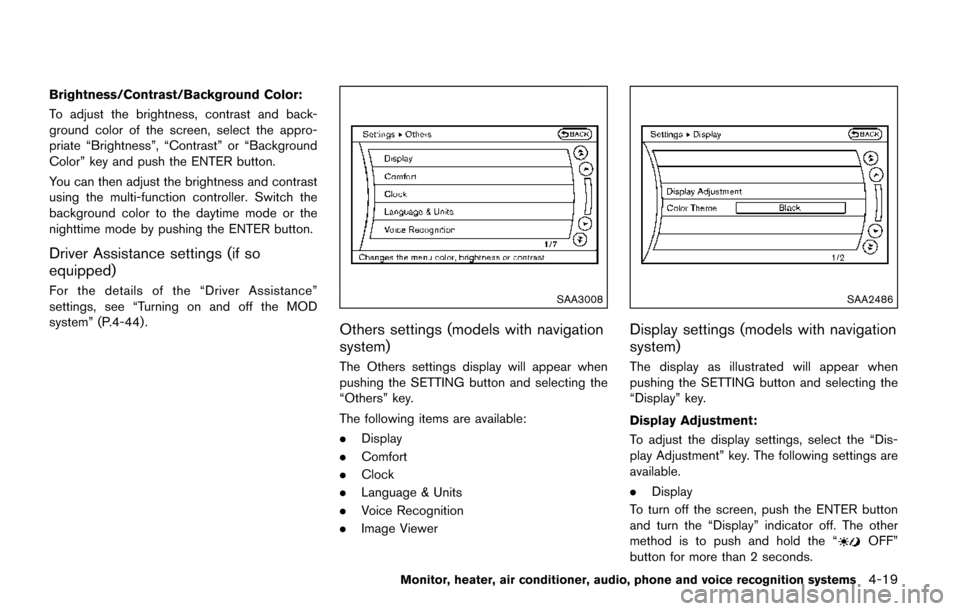
The Others settings display will appear when
pushing the SETTING button and selecting the
“Others” key.
The following items are available:
.Display
. Comfort
. Clock
. Language & Units
. Voice Recognition
. Image Viewer
SAA2486
Display settings (models with navigation
system)
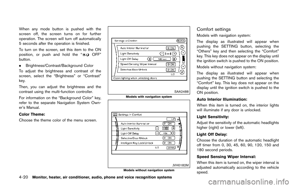
The display as illustrated will appear when
pushing the SETTING button and selecting the
“Display” key.
Display Adjustment:
To adjust the display settings, select the “Dis-
play Adjustment” key. The following settings are
available.
.Display
To turn off the screen, push the ENTER button
and turn the “Display” indicator off. The other
method is to push and hold the “
OFF”
button for more than 2 seconds.
Monitor, heater, air conditioner, audio, phone and voice recognition systems4-19
Page 209 of 520
4-20Monitor, heater, air conditioner, audio, phone and voice recognition systems
When any mode button is pushed with the
screen off, the screen turns on for further
operation. The screen will turn off automatically
5 seconds after the operation is finished.
To turn on the screen, set this item to the ON
position, or push and hold the “
OFF”
button.
. Brightness/Contrast/Background Color
To adjust the brightness and contrast of the
screen, select the “Brightness” or “Contrast”
key.
Then, you can adjust the brightness and the
contrast using the multi-function controller.
For information on the “Background Color” key,
refer to the separate Navigation System Own-
er’s Manual.
Color Theme:
Choose the theme color of the menu screen.
SAA2488
Models with navigation system
JVH0182MModels without navigation system
Comfort settings
Models with navigation system:
The display as illustrated will appear when
pushing the SETTING button, selecting the
“Others” key and then selecting the “Comfort”
key. This key does not appear on the display until
the ignition switch is pushed to the ON position.
Models without navigation system:
The display as illustrated will appear when
pushing the SETTING button and selecting the
“Comfort” key. This key does not appear on the
display until the ignition switch is pushed to the
ON position.
Auto Interior Illumination:
When this item is turned on, the interior lights
will illuminate if any door is unlocked.
Light Sensitivity:
Adjust the sensitivity of the automatic headlights
higher (right) or lower (left) .
Light Off Delay:
Choose the duration of the automatic headlight
off timer from 0, 30, 45, 60, 90, 120, 150 and
180 second periods.
Speed Sensing Wiper Interval:
When this item is turned on, the wiper interval is
adjusted automatically according to the vehicle
speed.