Page 411 of 520
6-6In case of emergency
JVE0032X
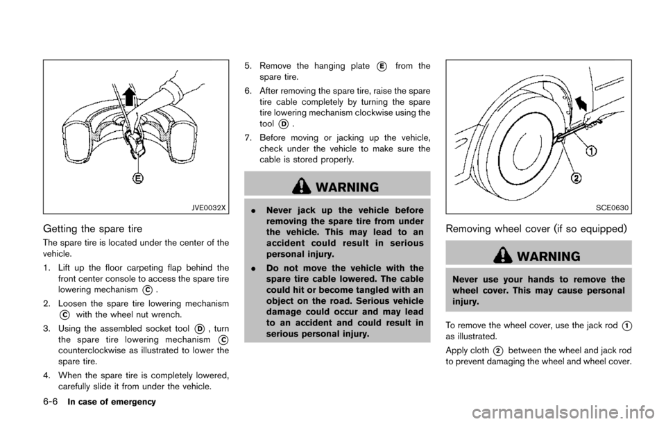
Getting the spare tire
The spare tire is located under the center of the
vehicle.
1. Lift up the floor carpeting flap behind thefront center console to access the spare tire
lowering mechanism
*C.
2. Loosen the spare tire lowering mechanism
*Cwith the wheel nut wrench.
3. Using the assembled socket tool
*D, turn
the spare tire lowering mechanism
*C
counterclockwise as illustrated to lower the
spare tire.
4. When the spare tire is completely lowered, carefully slide it from under the vehicle. 5. Remove the hanging plate
*Efrom the
spare tire.
6. After removing the spare tire, raise the spare tire cable completely by turning the spare
tire lowering mechanism clockwise using the
tool
*D.
7. Before moving or jacking up the vehicle, check under the vehicle to make sure the
cable is stored properly.
WARNING
.Never jack up the vehicle before
removing the spare tire from under
the vehicle. This may lead to an
accident could result in serious
personal injury.
. Do not move the vehicle with the
spare tire cable lowered. The cable
could hit or become tangled with an
object on the road. Serious vehicle
damage could occur and may lead
to an accident and could result in
serious personal injury.SCE0630
Removing wheel cover (if so equipped)
WARNING
Never use your hands to remove the
wheel cover. This may cause personal
injury.
To remove the wheel cover, use the jack rod
*1
as illustrated.
Apply cloth
*2between the wheel and jack rod
to prevent damaging the wheel and wheel cover.
Page 412 of 520
Jacking up the vehicle and removing the
flat tire
WARNING
.Never get under the vehicle while it
is supported only by the jack. If it is
necessary to work under the vehicle,
support it with safety stands.
. Use only the jack provided with your
vehicle to lift the vehicle. Do not use
the jack provided with your vehicle
on other vehicles. The jack is de-
signed for lifting only your vehicle
during a tire change.
. Use the correct jack-up points.
Never use any other part of the
vehicle for jack support.
. Never jack up the vehicle more than
necessary.
. Never use blocks on or under the
jack.
. Do not start or run the engine while
vehicle is on the jack, as it may
cause the vehicle to move.
. Do not allow passengers to stay in
the vehicle while it is on the jack. Carefully read the caution label attached
to the jack body and the following instruc-
tions.
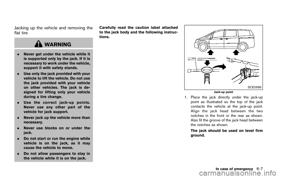
SCE0585
Jack-up point
1. Place the jack directly under the jack-up
point as illustrated so the top of the jack
contacts the vehicle at the jack-up point.
Align the jack head between the two
notches in the front or the rear as shown.
Also fit the groove of the jack head between
the notches as shown.
The jack should be used on level firm
ground.
In case of emergency6-7
Page 413 of 520
6-8In case of emergency
SCE0504
2. Loosen each wheel nut one or two turns byturning counterclockwise with the wheel nut
wrench. Do not remove the wheel nuts
until the tire is off the ground.
3. To lift the vehicle, securely hold the jack lever and rod with both hands as shown above.
Carefully raise the vehicle until the tire clears
the ground. Remove the wheel nuts, and
then remove the tire.
SCE0039
Installing the spare tire
The spare tire is designed for emergency
use. (See specific instructions under the
heading “Wheels and tires” (P.8-27) .)
1. Clean any mud or dirt from the surfacebetween the wheel and hub.
2. Carefully put the spare tire on and tighten the wheel nuts finger tight. Check that all the
wheel nuts contact the wheel surface
horizontally.
3. With the wheel nut wrench, tighten wheel nuts alternately and evenly in the sequence
illustrated (
*1,*2,*3,*4,*5) , more
than 2 times, until they are tight.
Page 431 of 520
8-2Do-it-yourself
When performing any inspection or mainte-
nance work on your vehicle, always take care
to prevent serious accidental injury to yourself or
damage to the vehicle. The following are general
precautions which should be closely observed.
WARNING
.Park the vehicle on a level surface,
apply the parking brake securely
and block the wheels to prevent
the vehicle from moving. Move the
shift lever to P (Park) .
. Be sure the ignition switch is in the
OFF or LOCK position when per-
forming any parts replacement or
repairs.
. If you must work with the engine
running, keep your hands, clothing,
hair and tools away from moving
fans, belts and any other moving
parts.
. It is advisable to secure or remove
any loose clothing and remove any
jewelry, such as rings, watches, etc.
before working on your vehicle.
. Always wear eye protection when-
ever you work on your vehicle. .
If you must run the engine in an
enclosed space such as a garage, be
sure there is proper ventilation for
exhaust gases to escape.
. Never get under the vehicle while it
is supported only by a jack. If it is
necessary to work under the vehicle,
support it with safety stands.
. Keep smoking materials, flame and
sparks away from fuel tank and the
battery.
. Because the fuel lines on gasoline
engine models are under high pres-
sure even when the engine is off, it
is recommended you visit a NISSAN
dealer for service of the fuel filter or
fuel lines.
CAUTION
.Do not work under the hood while
the engine is hot. Turn the engine
off and wait until it cools down.
. Avoid direct contact with used en-
gine oil and coolant. Improperly
disposed engine oil, and engine
coolant and/or other vehicle fluids can damage the environment. Al-
ways conform to local regulations
for disposal of vehicle fluid.
. Never leave the engine or the CVT
related component harnesses dis-
connected while the ignition switch
is in the ON position.
. Never connect or disconnect the
battery or any transistorized com-
ponent while the ignition switch is
in the ON position.
. Your vehicle is equipped with an
automatic engine cooling fan. It may
come on at any time without warn-
ing, even if the ignition key is in the
OFF position and the engine is not
running. To avoid injury, always
disconnect the negative battery
cable before working near the fan.
This “8. Do-it-yourself” section gives instruc-
tions regarding only those items which are
relatively easy for an owner to perform.
A genuine NISSAN Service Manual is also
available. (See “Owner’s manual/service manual
order information” (P.10-27) .)
You should be aware that incomplete or
improper servicing may result in operating
MAINTENANCE PRECAUTIONS
Page 436 of 520
SDI2717
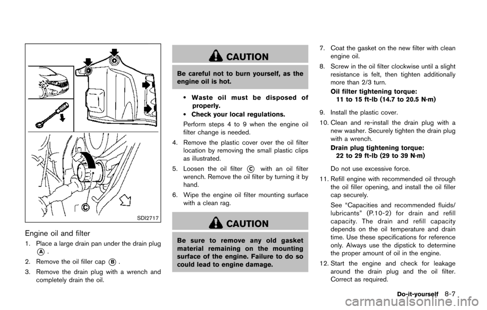
Engine oil and filter
1. Place a large drain pan under the drain plug
*A.
2. Remove the oil filler cap
*B.
3. Remove the drain plug with a wrench and completely drain the oil.
CAUTION
Be careful not to burn yourself, as the
engine oil is hot.
.Waste oil must be disposed of
properly.
.Check your local regulations.
Perform steps 4 to 9 when the engine oil
filter change is needed.
4. Remove the plastic cover over the oil filter location by removing the small plastic clips
as illustrated.
5. Loosen the oil filter
*Cwith an oil filter
wrench. Remove the oil filter by turning it by
hand.
6. Wipe the engine oil filter mounting surface with a clean rag.
CAUTION
Be sure to remove any old gasket
material remaining on the mounting
surface of the engine. Failure to do so
could lead to engine damage. 7. Coat the gasket on the new filter with clean
engine oil.
8. Screw in the oil filter clockwise until a slight resistance is felt, then tighten additionally
more than 2/3 turn.
Oil filter tightening torque:
11 to 15 ft-lb (14.7 to 20.5 N·m)
9. Install the plastic cover.
10. Clean and re-install the drain plug with a new washer. Securely tighten the drain plug
with a wrench.
Drain plug tightening torque:22 to 29 ft-lb (29 to 39 N·m)
Do not use excessive force.
11. Refill engine with recommended oil through the oil filler opening, and install the oil filler
cap securely.
See “Capacities and recommended fluids/
lubricants” (P.10-2) for drain and refill
capacity. The drain and refill capacity
depends on the oil temperature and drain
time. Use these specifications for reference
only. Always use the dipstick to determine
the proper amount of oil in the engine.
12. Start the engine and check for leakage around the drain plug and the oil filter.
Correct as required.
Do-it-yourself8-7
Page 441 of 520
8-12Do-it-yourself
JUMP STARTING
If jump starting is necessary, see “Jump starting”
(P.6-10) . If the engine does not start by jump
starting, the battery may have to be replaced. It
is recommended you visit a NISSAN dealer for
this service.CAUTION
.Do not ground accessories directly
to the battery terminal. Doing so will
bypass the variable voltage control
system and the vehicle battery may
not charge completely.
. Use electrical accessories with the
engine running to avoid discharging
the vehicle battery.
The variable voltage control system measures
the amount of electrical discharge from the
battery and controls voltage generated by the
generator.
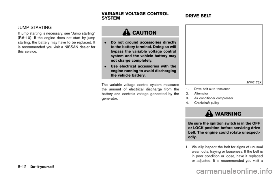
JVM0172X
1. Drive belt auto-tensioner
2. Alternator
3. Air conditioner compressor
4. Crankshaft pulley
WARNING
Be sure the ignition switch is in the OFF
or LOCK position before servicing drive
belt. The engine could rotate unexpect-
edly.
1. Visually inspect the belt for signs of unusual wear, cuts, fraying or looseness. If the belt is
in poor condition or loose, have it replaced
or adjusted. It is recommended you visit a
VARIABLE VOLTAGE CONTROL
SYSTEM DRIVE BELT
Page 444 of 520
REPLACING
CAUTION
.After wiper blade replacement, re-
turn the wiper arm to its original
position; otherwise it may be da-
maged when the hood is opened.
. Make sure the wiper blades contact
the glass; otherwise the arm may be
damaged from wind pressure.
SDI2694
Type A (if so equipped)
Replace the wiper blades if they are worn.
1. Pull the wiper arm.When lifting the wiper
arm, lift the driver’s side first, then the
passenger’s side. Otherwise, the wiper
blades may be scratched and may
cause damage.
2. Release the lock tab
*1and then move the
wiper blade
*2as illustrated.
3. Remove the wiper blade.
4. Insert the new wiper blade onto the wiper arm until it clicks into place.
It is recommended you visit a NISSAN dealer for
wiper blade rubber replacement.
Do-it-yourself8-15
Page 449 of 520
8-20Do-it-yourself
NOTE:
If the extended storage fuse switch mal-
functions, or if the fuse is open, it is not
necessary to replace the switch. In this
case, remove the extended storage fuse
switch and replace it with a new fuse of the
same rating.
How to remove the extended storage fuse
switch:
1. To remove the extended storage fuse switch,be sure the ignition switch is in the OFF or
LOCK position.
2. Be sure the headlight switch is in the OFF position.
3. Remove the fuse box cover.
4. Pinch the locking tabs
*1found on each
side of the storage fuse switch.
5. Pull the storage fuse switch straight out from the fuse box
*2.
CAUTION
Be careful not to allow children to
swallow the battery and removed parts.
SDI2451
Replace the battery as follows:
1. Remove the mechanical key from the key.
2. Insert a small screwdriver into the slit of thecorner and twist it to separate the upper part
from the lower part. Use a cloth to protect
the casing.
INTELLIGENT KEY BATTERY
REPLACEMENT