2017 NISSAN QUEST check engine light
[x] Cancel search: check engine lightPage 394 of 520
SSD1178
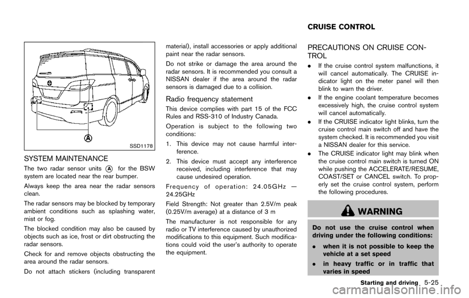
SYSTEM MAINTENANCE
The two radar sensor units*Afor the BSW
system are located near the rear bumper.
Always keep the area near the radar sensors
clean.
The radar sensors may be blocked by temporary
ambient conditions such as splashing water,
mist or fog.
The blocked condition may also be caused by
objects such as ice, frost or dirt obstructing the
radar sensors.
Check for and remove objects obstructing the
area around the radar sensors.
Do not attach stickers (including transparent material) , install accessories or apply additional
paint near the radar sensors.
Do not strike or damage the area around the
radar sensors. It is recommended you consult a
NISSAN dealer if the area around the radar
sensors is damaged due to a collision.
Radio frequency statement
This device complies with part 15 of the FCC
Rules and RSS-310 of Industry Canada.
Operation is subject to the following two
conditions:
1. This device may not cause harmful inter-
ference.
2. This device must accept any interference received, including interference that may
cause undesired operation.
Frequency of operation: 24.05GHz —
24.25GHz
Field Strength: Not greater than 2.5V/m peak
(0.25V/m average) at a distance of 3 m
The manufacturer is not responsible for any
radio or TV interference caused by unauthorized
modifications to this equipment. Such modifica-
tions could void the user’s authority to operate
the equipment.
PRECAUTIONS ON CRUISE CON-
TROL
. If the cruise control system malfunctions, it
will cancel automatically. The CRUISE in-
dicator light on the meter panel will then
blink to warn the driver.
. If the engine coolant temperature becomes
excessively high, the cruise control system
will cancel automatically.
. If the CRUISE indicator light blinks, turn the
cruise control main switch off and have the
system checked. It is recommended you visit
a NISSAN dealer for this service.
. The CRUISE indicator light may blink when
the cruise control main switch is turned ON
while pushing the ACCELERATE/RESUME,
COAST/SET or CANCEL switch. To prop-
erly set the cruise control system, perform
the following procedures.
WARNING
Do not use the cruise control when
driving under the following conditions:
. when it is not possible to keep the
vehicle at a set speed
. in heavy traffic or in traffic that
varies in speed
Starting and driving5-25
CRUISE CONTROL
Page 399 of 520
5-30Starting and driving
WARNING
.If the engine is not running or is
turned off while driving, the power
assist for the steering will not work.
Steering will be harder to operate.
. When the hydraulic pump electric
power steering warning light illumi-
nates with the engine running, the
power assist for the steering will
cease operation. You will still have
control of the vehicle, but the steer-
ing will be much harder to operate.
The hydraulic pump electric power steering is
designed to provide power assistance while
driving to operate the steering wheel with light
force.
When the steering wheel is operated repeatedly
or continuously while parking or driving at a very
low speed, the power assist for the steering
wheel will be reduced. This is to prevent
overheating of the hydraulic pump electric
power steering and protect it from getting
damaged. While the power assist is reduced,
steering wheel operation will become heavy.
When the temperature of the power steering
system goes down, the power assist level will return to normal. Avoid repeating such steering
wheel operations that could cause the hydraulic
pump electric power steering to overheat.
You may hear a noise from the front of the
vehicle when the steering wheel is operated.
This is not a malfunction.
If the hydraulic pump electric power steering
warning light illuminates while the engine is
running, it may indicate the hydraulic pump
electric power steering is not functioning prop-
erly and may need servicing. It is recommended
you have the hydraulic pump electric power
steering checked by a NISSAN dealer.
When the hydraulic pump electric power steer-
ing warning light illuminates with the engine
running, the power assist for the steering will
cease operation but you will still have control of
the vehicle. At this time, greater steering efforts
are required to operate the steering wheel,
especially in sharp turns and at low speeds.
BRAKING PRECAUTIONS
The brake system has two separate hydraulic
circuits. If one circuit malfunctions, you will still
have braking at two wheels.
Vacuum assisted brakes
The brake booster aids braking by using engine
vacuum. If the engine stops, you can stop the
vehicle by depressing the brake pedal. However,
greater foot pressure on the brake pedal will be
required to stop the vehicle and the stopping
distance will be longer.
Using the brakes
Avoid resting your foot on the brake pedal while
driving. This will cause overheating of the
brakes, wearing out the brake and pads faster
and reduce gas mileage.
To help reduce brake wear and to prevent the
brakes from overheating, reduce speed and
downshift to a lower gear before going down a
slope or long grade. Overheated brakes may
reduce braking performance and could result in
loss of vehicle control.
WARNING
.
While driving on a slippery surface,
be careful when braking, accelerat-
HYDRAULIC PUMP ELECTRIC
POWER STEERING BRAKE SYSTEM
Page 401 of 520
5-32Starting and driving
Self-test feature
The ABS includes electronic sensors, electric
pumps, hydraulic solenoids and a computer. The
computer has a built-in diagnostic feature that
tests the system each time you start the engine
and move the vehicle at a low speed in forward
or reverse. When the self-test occurs, you may
hear a “clunk” noise and/or feel a pulsation in the
brake pedal. This is normal and does not
indicate a malfunction. If the computer senses
a malfunction, it switches the ABS off and
illuminates the ABS warning light on the
instrument panel. The brake system then oper-
ates normally, but without anti-lock assistance.
If the ABS warning light illuminates during the
self-test or while driving, have the vehicle
checked. It is recommended you visit a NISSAN
dealer for this service.
Normal operation
The ABS operates at speeds above 3 to 6 MPH
(5 to 10 km/h) . The speed varies according to
road conditions.
When the ABS senses that one or more wheels
are close to locking up, the actuator rapidly
applies and releases hydraulic pressure. This
action is similar to pumping the brakes very
quickly. You may feel a pulsation in the brake
pedal and hear a noise from under the hood orfeel a vibration from the actuator when it is
operating. This is normal and indicates that the
ABS is operating properly. However, the pulsa-
tion may indicate that road conditions are
hazardous and extra care is required while
driving.
The Vehicle Dynamic Control (VDC) system
uses various sensors to monitor driver inputs
and vehicle motion. Under certain driving con-
ditions, the VDC system helps to perform the
following functions.
.
Controls brake pressure to reduce wheel
slip on one slipping drive wheel so power is
transferred to a non slipping drive wheel on
the same axle.
. Controls brake pressure and engine output
to reduce drive wheel slip based on vehicle
speed (traction control function) .
. Controls brake pressure at individual wheels
and engine output to help the driver maintain
control of the vehicle in the following
conditions:
— understeer (vehicle tends to not follow
the steered path despite increased
steering input)
— oversteer (vehicle tends to spin due to certain road or driving conditions) .
The VDC system can help the driver to maintain
control of the vehicle, but it cannot prevent loss
of vehicle control in all driving situations.
When the VDC system operates, the VDC
warning light
in the instrument panel flashes
so note the following:
. The road may be slippery or the system may
determine some action is required to help
VEHICLE DYNAMIC CONTROL (VDC)
SYSTEM
Page 403 of 520
5-34Starting and driving
ing lightmay illuminate.
. The VDC system is not a substitute
for winter tires or tire chains on a
snow covered road.FREEING A FROZEN DOOR LOCK
To prevent a door lock from freezing, apply
deicer through the key hole. If the lock becomes
frozen, heat the key before inserting it into the
key hole or use the remote keyless entry key fob.
ANTI-FREEZE
In the winter when it is anticipated that the
outside temperature will drop below 328F(0 8C) ,
check the anti-freeze to assure proper winter
protection. For additional information, see “En-
gine cooling system” (P.8-4) .
BATTERY
If the battery is not fully charged during
extremely cold weather conditions, the battery
fluid may freeze and damage the battery. To
maintain maximum efficiency, the battery should
be checked regularly. For additional information,
see “Battery” (P.8-10) .
DRAINING OF COOLANT WATER
If the vehicle is to be left outside without anti-
freeze, drain the cooling system, including the
engine block. Refill before operating the vehicle.
For details, see “Engine cooling system” (P.8-4) .
TIRE EQUIPMENT
SUMMER tires have a tread designed to provide
superior performance on dry pavement. How-
ever, the performance of these tires will be
substantially reduced in snowy and icy condi-
tions. If you operate your vehicle on snowy or icy
roads, NISSAN recommends the use of MUD &
SNOW or ALL SEASON tires on all four wheels.
It is recommended you consult a NISSAN dealer
for the tire type, size, speed rating and
availability information.
For additional traction on icy roads, studded
tires may be used. However, some U.S. states
and Canadian provinces prohibit their use.
Check local, state and provincial laws before
installing studded tires.
Skid and traction capabilities of studded
snow tires, on wet or dry surfaces, may be
poorer than that of non-studded snow
tires.
Tire chains may be used. For details, see “Tire
chains” (P.8-33) .
SPECIAL WINTER EQUIPMENT
It is recommended that the following items be
carried in the vehicle during winter:
. A scraper and stiff-bristled brush to remove
ice and snow from the windows and wiper
blades.
COLD WEATHER DRIVING
Page 408 of 520
To shut off the engine in an emergency situation
while driving perform the following procedure:
.Rapidly push the push-button ignition switch
3 consecutive times in less than 1.5
seconds, or
. Push and hold the push-button ignition
switch for more than 2 seconds.TIRE PRESSURE MONITORING SYS-
TEM (TPMS)
This vehicle is equipped with the Tire Pressure
Monitoring System (TPMS) . It monitors tire
pressure of all tires except the spare. When
the low tire pressure warning light is lit and the
CHECK TIRE PRESSURE warning appears on
the vehicle information display, one or more of
your tires is significantly under-inflated. If the
vehicle is being driven with low tire pressure, the
TPMS will activate and warn you of it by the low
tire pressure warning light. This system will
activate only when the vehicle is driven at
speeds above 16 MPH (25 km/h) . For more
details, see “Warning lights, indicator lights and
audible reminders” (P.2-11) and “Tire Pressure
Monitoring System (TPMS)” (P.5-3) .
WARNING
.If the low tire pressure warning light
illuminates while driving, avoid sud-
den steering maneuvers or abrupt
braking, reduce vehicle speed, pull
off the road to a safe location and
stop the vehicle as soon as possi-
ble. Driving with under-inflated tires
may permanently damage the tires
and increase the likelihood of tire failure. Serious vehicle damage
could occur and may lead to an
accident and could result in serious
personal injury. Check the tire pres-
sure for all four tires. Adjust the tire
pressure to the recommended COLD
tire pressure shown on the Tire and
Loading Information label to turn
the low tire pressure warning light
OFF. If the light still illuminates
while driving after adjusting the tire
pressure, a tire may be flat. If you
have a flat tire, replace it with a
spare tire as soon as possible.
. Since the spare tire is not equipped
with the TPMS, when a spare tire is
mounted or a wheel is replaced, the
TPMS will not function and the low
tire pressure warning light will flash
for approximately 1 minute. The
light will remain on after 1 minute.
Have your tires replaced and/or
TPMS system reset as soon as
possible. It is recommended you
visit a NISSAN dealer for these
services.
. Replacing tires with those not ori-
ginally specified by NISSAN could
affect the proper operation of the
In case of emergency6-3
EMERGENCY ENGINE SHUT OFF FLAT TIRE
Page 430 of 520
8 Do-it-yourself
Maintenance precautions ........................................................ 8-2
Engine compartment check locations .................................. 8-3VQ35DE engine .................................................................. 8-3
Engine cooling system ............................................................. 8-4 Checking engine coolant level ......................................... 8-5
Changing engine coolant .................................................. 8-5
Engine oil ........................................................................\
............ 8-5 Checking engine oil level .................................................. 8-5
Changing engine oil and filter .......................................... 8-6
Continuously Variable Transmission (CVT) fluid ............... 8-8
Power steering fluid .................................................................. 8-8
Brake fluid ........................................................................\
........... 8-9
Window washer fluid ............................................................ 8-10
Battery ........................................................................\
............... 8-10 Jump starting ..................................................................... 8-12
Variable voltage control system .......................................... 8-12
Drive belt ........................................................................\
.......... 8-12
Spark plugs ........................................................................\
..... 8-13 Replacing spark plugs .................................................... 8-13
Air cleaner ........................................................................\
........ 8-14 Windshield wiper blades ..................................................... 8-14
Cleaning ........................................................................\
... 8-14
Replacing ........................................................................\
. 8-15
Washer nozzle ................................................................ 8-16
Rear window wiper blade ................................................... 8-17
Brakes ........................................................................\
.............. 8-17
Self-adjusting brakes .................................................... 8-17
Brake pad wear warning .............................................. 8-17
Fuses ........................................................................\
................ 8-18 Engine compartment ..................................................... 8-18
Passenger compartment .............................................. 8-19
Intelligent Key battery replacement ................................... 8-20
Lights ........................................................................\
................ 8-22
Headlights ........................................................................\
8-22
Exterior and interior lights ............................................ 8-24
Wheels and tires ................................................................... 8-27
Tire pressure ................................................................... 8-27
Tire labeling ..................................................................... 8-31
Types of tires ................................................................... 8-33
Tire chains ....................................................................... 8-33
Changing wheels and tires .......................................... 8-35
Page 436 of 520
SDI2717
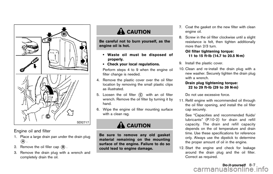
Engine oil and filter
1. Place a large drain pan under the drain plug
*A.
2. Remove the oil filler cap
*B.
3. Remove the drain plug with a wrench and completely drain the oil.
CAUTION
Be careful not to burn yourself, as the
engine oil is hot.
.Waste oil must be disposed of
properly.
.Check your local regulations.
Perform steps 4 to 9 when the engine oil
filter change is needed.
4. Remove the plastic cover over the oil filter location by removing the small plastic clips
as illustrated.
5. Loosen the oil filter
*Cwith an oil filter
wrench. Remove the oil filter by turning it by
hand.
6. Wipe the engine oil filter mounting surface with a clean rag.
CAUTION
Be sure to remove any old gasket
material remaining on the mounting
surface of the engine. Failure to do so
could lead to engine damage. 7. Coat the gasket on the new filter with clean
engine oil.
8. Screw in the oil filter clockwise until a slight resistance is felt, then tighten additionally
more than 2/3 turn.
Oil filter tightening torque:
11 to 15 ft-lb (14.7 to 20.5 N·m)
9. Install the plastic cover.
10. Clean and re-install the drain plug with a new washer. Securely tighten the drain plug
with a wrench.
Drain plug tightening torque:22 to 29 ft-lb (29 to 39 N·m)
Do not use excessive force.
11. Refill engine with recommended oil through the oil filler opening, and install the oil filler
cap securely.
See “Capacities and recommended fluids/
lubricants” (P.10-2) for drain and refill
capacity. The drain and refill capacity
depends on the oil temperature and drain
time. Use these specifications for reference
only. Always use the dipstick to determine
the proper amount of oil in the engine.
12. Start the engine and check for leakage around the drain plug and the oil filter.
Correct as required.
Do-it-yourself8-7
Page 447 of 520
8-18Do-it-yourself
SDI2181
ENGINE COMPARTMENT
WARNING
Never use a fuse of a higher or lower
amperage rating than that specified on
the fuse box cover. This could damage
the electrical system or electronic con-
trol units or cause a fire.
If any electrical equipment does not operate,
check for an open fuse.
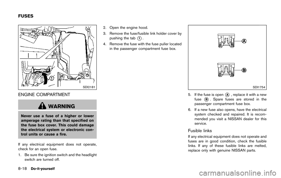
1. Be sure the ignition switch and the headlight switch are turned off. 2. Open the engine hood.
3. Remove the fuse/fusible link holder cover by
pushing the tab
*1.
4. Remove the fuse with the fuse puller located in the passenger compartment fuse box.
SDI1754
5. If the fuse is open*A, replace it with a new
fuse
*B. Spare fuses are stored in the
passenger compartment fuse box.
6. If a new fuse also opens, have the electrical system checked and repaired. It is recom-
mended you visit a NISSAN dealer for this
service.
Fusible links
If any electrical equipment does not operate and
fuses are in good condition, check the fusible
links. If any of these fusible links are melted,
replace only with genuine NISSAN parts.
FUSES