2017 NISSAN ARMADA ECU
[x] Cancel search: ECUPage 586 of 614
4. The resulting figure equals the avail-able amount of cargo and luggage
load capacity. For example, if the XXX
amount equals 1400 lbs. and there
will be five 150 lb. passengers in your
vehicle, the amount of available cargo
and luggage load capacity is 650 lbs.
(1400 �í750 (5 x 150) = 650 lbs) or
(640 �í340 (5 x 70) = 300 kg.)
5. Determine the combined weight of luggage and cargo being loaded on
the vehicle. That weight may not
safely exceed the available cargo
and luggage load capacity calculated
in Step 4.
6. If your vehicle will be towing a trailer, load from your trailer will be trans-
ferred to your vehicle. Consult this
manual to determine how this re-
duces the available cargo and lug-
gage load capacity of your vehicle.
Before driving a loaded vehicle, confirm
that you do not exceed the Gross Vehicle
Weight Rating (GVWR) or the Gross
Axle Weight Rating (GAWR) for your vehicle. (See “Measurement of weights”
(P.10-16) .)
Also check tires for proper inflation
pressures. See the Tire and Loading
Information label.
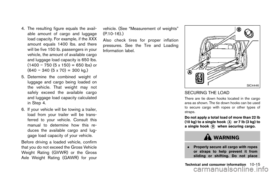
SIC4446
SECURING THE LOAD
There are tie down hooks located in the cargo
area as shown. The tie down hooks can be used
to secure cargo with ropes or other types of
straps.
Do not apply a total load of more than 22 lb
(10 kg) to a single hook
*Aor 7 lb (3 kg) to
a single hook
*Bwhen securing cargo.
WARNING
. Properly secure all cargo with ropes
or straps to help prevent it from
sliding or shifting. Do not place
Technical and consumer information10-15
Page 587 of 614
10-16Technical and consumer information
cargo higher than the seatbacks. In
a sudden stop or collision, unse-
cured cargo could cause personal
injury.
. The child restraint top tether strap
may be damaged by contact with
items in the cargo area. Secure any
items in the cargo area. Your child
could be seriously injured or killed
in a collision if the top tether strap is
damaged.
. Do not load your vehicle any heavier
than the GVWR or the maximum
front and rear GAWRs. If you do,
parts of your vehicle can break, tire
damage could occur, or it can
change the way your vehicle han-
dles. This could result in loss of
control and cause personal injury.
LOADING TIPS
.The GVW must not exceed GVWR or
GAWR as specified on the F.M.V.S.
S./C.M.V.S.S. certification label.
.Do not load the front and rear axle to
the GAWR. Doing so will exceed the
GVWR.
WARNING
.Properly secure all cargo to
help prevent it from sliding or
shifting. Do not place cargo
higher than the seatbacks. In a
sudden stop or collision, un-
secured cargo could cause
personal injury.
. Do not load your vehicle any
heavier than the GVWR or the
maximum front and rear
GAWRs. If you do, parts of
your vehicle can break, tire
damage could occur, or it can
change the way your vehicle
handles. This could result in
loss of control and cause per-
sonal injury.
. Overloading not only can
shorten the life of your vehicle
and the tire, but can cause
unsafe vehicle handling and
long braking distance. This may cause a premature tire
failure, which could result in a
serious accident and personal
injury. Failures caused by
overloading are not covered
by the vehicle’s warranty.
MEASUREMENT OF WEIGHTS
Secure loose items to prevent weight
shifts that could affect the balance of
your vehicle. When the vehicle is loaded,
drive to a scale and weigh the front and
the rear wheels separately to determine
axle loads. Individual axle loads should
not exceed either of the gross axle
weight ratings (GAWR) . The total of the
axle loads should not exceed the gross
vehicle weight rating (GVWR) . These
ratings are given on the vehicle certifica-
tion label. If weight ratings are exceeded,
move or remove items to bring all
weights below the ratings.
Page 594 of 614
the weight rating of the hitch compo-
nents. Never exceed the weight rating
of the hitch components. Doing so can
cause serious personal injury or prop-
erty damage.
Hitch ball
Choose a hitch ball of the proper size and
weight rating for your trailer:
.The required hitch ball size is stamped on
most trailer couplers. Most hitch balls also
have the size printed on top of the ball.
. Choose the proper class hitch ball based on
the trailer weight.
. The diameter of the threaded shank of the
hitch ball must be matched to the ball mount
hole diameter. The hitch ball shank should
be no more than 1/16´´ smaller than the hole
in the ball mount.
. The threaded shank of the hitch ball must be
long enough to be properly secured to the
ball mount. There should be at least 2
threads showing beyond the lock washer
and nut.
Ball mount
The hitch ball is attached to the ball mount and
the ball mount is inserted into the hitch receiver.
Choose a proper class ball mount based on the
trailer weight. Additionally, the ball mount should
be chosen to keep the trailer tongue level with
the ground.
Weight carrying hitches
A weight carrying or “dead weight” ball mount is
one that is designed to carry the whole amount
of tongue weight and gross weight directly on
the ball mount and on the receiver.
Weight distribution hitch
This type of hitch is also called a “load-leveling”
or “equalizing” hitch. A set of bars attach to the
ball mount and to the trailer to distribute the
tongue weight (hitch weight) of your trailer.
Many vehicles cannot carry the full tongue
weight of a given trailer, and need some of the
tongue weight transferred through the frame and
pushing down on the front wheels. This gives
stability to the tow vehicle.
A weight-distributing hitch system (Class IV) is
recommended if you plan to tow trailers with a
maximum weight over 5,000 lbs (2,267 kg) .
Check with the trailer and towing equipment
manufacturers to determine if they recommend
the use of a weight-distributing hitch system. NOTE:
A weight-distributing hitch system may
affect the operation of trailer surge brakes.
If you are considering use of a weight-
distributing hitch system with a surge
brake-equipped trailer, check with the
surge brake, hitch or trailer manufacturer
to determine if and how this can be done.
Follow the instructions provided by the manu-
facturer for installing and using the weight-
distributing hitch system.
General set-up instructions are as follows:
1. Park unloaded vehicle on a level surface.
With the ignition switch in the ON position
and the doors closed, allow the vehicle to
stand for several minutes so that it can level.
2. Measure the height of a reference point on the front and rear bumpers at the center of
the vehicle.
3. Attach the trailer to the vehicle and adjust the hitch equalizers so that the front bumper
height is within 0 - .5 inches (0 - 13 mm) of
the reference height measured in step 2.
The rear bumper should be no higher than
the reference height measured in step 2.
Technical and consumer information10-23
Page 597 of 614
10-26Technical and consumer information
Several types of braking systems are available.
Surge Brakes -The surge brake actuator is
mounted on the trailer tongue with a hydraulic
line running to each trailer wheel. Surge brakes
are activated by the trailer pushing against the
hitch ball when the tow vehicle is braking.
Hydraulic surge brakes are common on rental
trailers and some boat trailers. In this type of
system, there is no hydraulic or electric connec-
tion for brake operation between the tow vehicle
and the trailer.
Electric Trailer Brakes - Electric braking
systems are activated by an electronic signal
sent from a trailer brake controller (special brake
sensing module) .
Have a professional supplier of towing equip-
ment make sure the trailer brakes are properly
installed and demonstrate proper brake function
testing.
WARNING
Never connect a trailer brake system
directly to the vehicle brake system.
Pre-towing tips
. Be certain your vehicle maintains a level
position when a loaded or unloaded trailer is
hitched. Do not drive the vehicle if it has an
abnormal nose-up or nose-down condition;
check for improper tongue load, overload,
worn suspension or other possible causes
of either condition.
. Always secure items in the trailer to prevent
load shift while driving.
. Keep the cargo load as low as possible in
the trailer to keep the trailer center of gravity
low.
. Load the trailer so approximately 60% of the
trailer load is in the front half and 40% is in
the back half. Also make sure the load is
balanced side to side.
. Check your hitch, trailer tire pressure,
vehicle tire pressure, trailer light operation,
and trailer wheel lug nuts every time you
attach a trailer to the vehicle.
. Be certain your rearview mirrors conform to
all federal, state or local regulations. If not,
install any mirrors required for towing before
driving the vehicle.
. Determine the overall height of the vehicle
and trailer so the required clearance is
known.
Trailer towing tips
In order to gain skill and an understanding of the
vehicle’s behavior, you should practice turning,
stopping and backing up in an area which is free
from traffic. Steering stability, and braking
performance will be somewhat different than
under normal driving conditions.
.Always secure items in the trailer to prevent
load shift while driving.
. Lock the trailer hitch coupler with a pin or
lock to prevent the coupler from inadver-
tently becoming unlatched.
. Avoid abrupt starts, acceleration or stops.
. Avoid sharp turns or lane changes.
. Always drive your vehicle at a moderate
speed. Some states or provinces have
specific speed limits for vehicles that are
towing trailers. Obey the local speed limits.
. When backing up, hold the bottom of the
steering wheel with one hand. Move your
hand in the direction in which you want the
trailer to go. Make small corrections and
back up slowly. If possible, have someone
guide you when you are backing up.
Always block the wheels on both vehicle and
trailer when parking. Parking on a slope is not
recommended; however, if you must do so:
Page 603 of 614
10-32Technical and consumer information
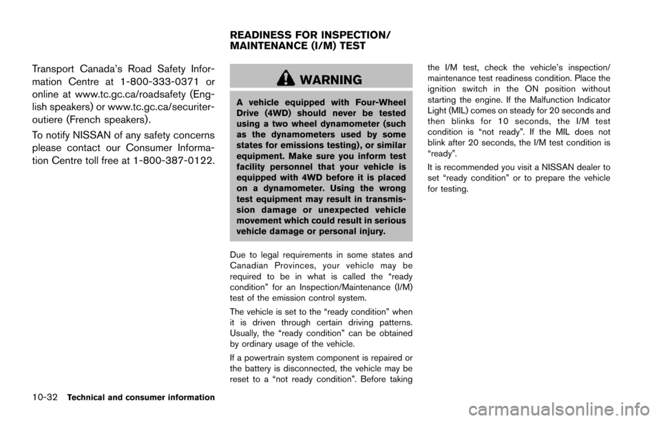
Transport Canada’s Road Safety Infor-
mation Centre at 1-800-333-0371 or
online at www.tc.gc.ca/roadsafety (Eng-
lish speakers) or www.tc.gc.ca/securiter-
outiere (French speakers) .
To notify NISSAN of any safety concerns
please contact our Consumer Informa-
tion Centre toll free at 1-800-387-0122.
WARNING
A vehicle equipped with Four-Wheel
Drive (4WD) should never be tested
using a two wheel dynamometer (such
as the dynamometers used by some
states for emissions testing) , or similar
equipment. Make sure you inform test
facility personnel that your vehicle is
equipped with 4WD before it is placed
on a dynamometer. Using the wrong
test equipment may result in transmis-
sion damage or unexpected vehicle
movement which could result in serious
vehicle damage or personal injury.
Due to legal requirements in some states and
Canadian Provinces, your vehicle may be
required to be in what is called the “ready
condition” for an Inspection/Maintenance (I/M)
test of the emission control system.
The vehicle is set to the “ready condition” when
it is driven through certain driving patterns.
Usually, the “ready condition” can be obtained
by ordinary usage of the vehicle.
If a powertrain system component is repaired or
the battery is disconnected, the vehicle may be
reset to a “not ready condition”. Before taking the I/M test, check the vehicle’s inspection/
maintenance test readiness condition. Place the
ignition switch in the ON position without
starting the engine. If the Malfunction Indicator
Light (MIL) comes on steady for 20 seconds and
then blinks for 10 seconds, the I/M test
condition is “not ready”. If the MIL does not
blink after 20 seconds, the I/M test condition is
“ready”.
It is recommended you visit a NISSAN dealer to
set “ready condition” or to prepare the vehicle
for testing.
READINESS FOR INSPECTION/
MAINTENANCE (I/M) TEST
Page 606 of 614
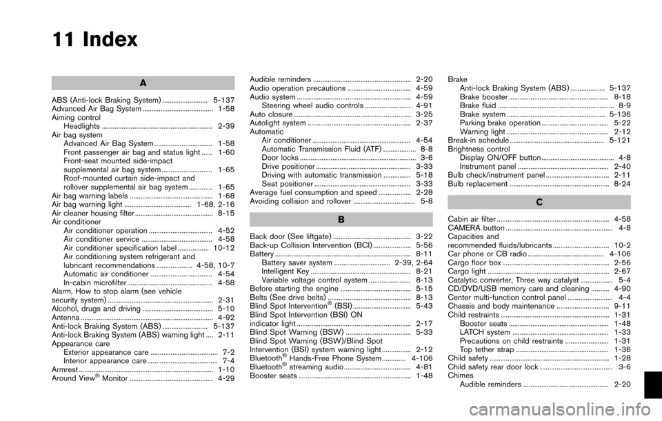
11 Index
A
ABS (Anti-lock Braking System) ......................... 5-137
Advanced Air Bag System ....................................... 1-58
Aiming controlHeadlights ............................................................. 2-39
Air bag system Advanced Air Bag System ................................ 1-58
Front passenger air bag and status light ...... 1-60
Front-seat mounted side-impact
supplemental air bag system ............................ 1-65
Roof-mounted curtain side-impact and
rollover supplemental air bag system ............. 1-65
Air bag warning labels .............................................. 1-68
Air bag warning light ..................................... 1-68, 2-16
Air cleaner housing filter ........................................... 8-15
Air conditioner Air conditioner operation ................................... 4-52
Air conditioner service ....................................... 4-58
Air conditioner specification label ................. 10-12
Air conditioning system refrigerant and
lubricant recommendations .................... 4-58, 10-7
Automatic air conditioner .................................. 4-54
In-cabin microfilter ............................................... 4-58
Alarm, How to stop alarm (see vehicle
security system) .......................................................... 2-31
Alcohol, drugs and driving ....................................... 5-10
Antenna ......................................................................... 4-92
Anti-lock Braking System (ABS) ......................... 5-137
Anti-lock Braking System (ABS) warning light .... 2-11
Appearance care Exterior appearance care ..................................... 7-2
Interior appearance care ....................................... 7-4
Armrest .......................................................................... 1-10
Around View
�ŠMonitor .............................................. 4-29 Audible reminders ...................................................... 2-20
Audio operation precautions ................................... 4-59
Audio system ............................................................... 4-59
Steering wheel audio controls ......................... 4-91
Auto closure ................................................................. 3-25
Autolight system ......................................................... 2-37
Automatic Air conditioner ...................................................... 4-54
Automatic Transmission Fluid (ATF) .................. 8-8
Door locks ................................................................ 3-6
Drive positioner .................................................... 3-33
Driving with automatic transmission ............... 5-18
Seat positioner ..................................................... 3-33
Average fuel consumption and speed .................. 2-28
Avoiding collision and rollover .................................. 5-8
B
Back door (See liftgate) ........................................... 3-22
Back-up Collision Intervention (BCI) ..................... 5-56
Battery ........................................................................... 8-11 Battery saver system ............................... 2-39, 2-64
Intelligent Key ....................................................... 8-21
Variable voltage control system ....................... 8-13
Before starting the engine ....................................... 5-15
Belts (See drive belts) .............................................. 8-13
Blind Spot Intervention
�Š(BSI) ................................ 5-43
Blind Spot Intervention (BSI) ON
indicator light ............................................................... 2-17
Blind Spot Warning (BSW) .................................... 5-33
Blind Spot Warning (BSW)/Blind Spot
Intervention (BSI) system warning light ................ 2-12
Bluetooth
�ŠHands-Free Phone System ............. 4-106
Bluetooth�Šstreaming audio ..................................... 4-81
Booster seats .............................................................. 1-48 Brake
Anti-lock Braking System (ABS) ................... 5-137
Brake booster ....................................................... 8-18
Brake fluid ................................................................ 8-9
Brake system ...................................................... 5-136
Parking brake operation ..................................... 5-22
Warning light ........................................................ 2-12
Break-in schedule .................................................... 5-121
Brightness control Display ON/OFF button ........................................ 4-8
Instrument panel .................................................. 2-40
Bulb check/instrument panel ................................... 2-11
Bulb replacement ....................................................... 8-24
C
Cabin air filter .............................................................. 4-58
CAMERA button ........................................................... 4-8
Capacities and
recommended fluids/lubricants ............................... 10-2
Car phone or CB radio .......................................... 4-106
Cargo floor box ........................................................... 2-56
Cargo light ................................................................... 2-67
Catalytic converter, Three way catalyst .................. 5-4
CD/DVD/USB memory care and cleaning .......... 4-90
Center multi-function control panel ......................... 4-4
Chassis and body maintenance ............................. 9-11
Child restraints ............................................................ 1-31 Booster seats ....................................................... 1-48
LATCH system ..................................................... 1-33
Precautions on child restraints ........................ 1-31
Top tether strap ................................................... 1-36
Child safety .................................................................. 1-28
Child safety rear door lock ........................................ 3-6
Chimes
Audible reminders ............................................... 2-20
Page 610 of 614
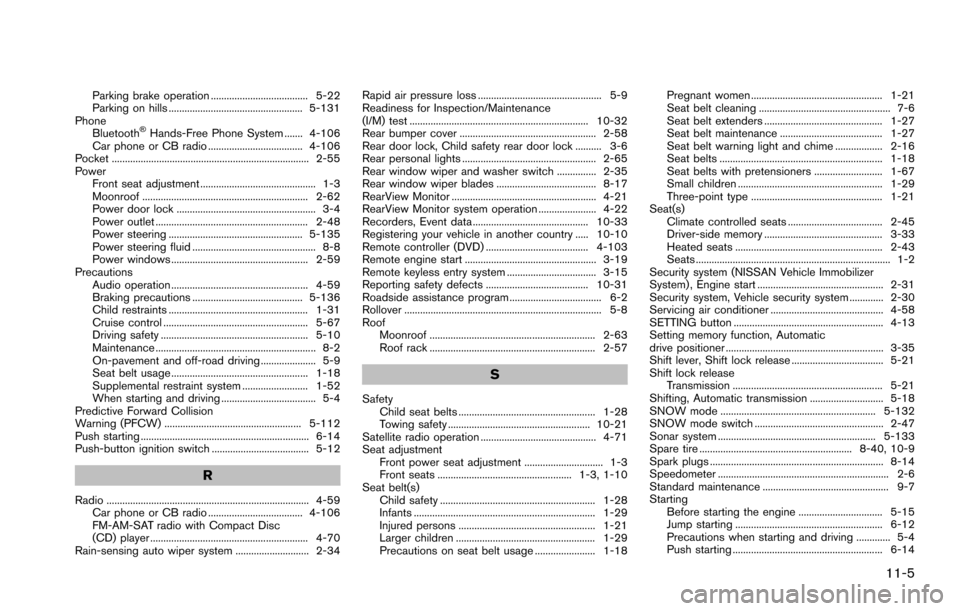
Parking brake operation ..................................... 5-22
Parking on hills ................................................... 5-131
Phone Bluetooth
�ŠHands-Free Phone System ....... 4-106
Car phone or CB radio .................................... 4-106
Pocket ........................................................................... 2-55
Power Front seat adjustment ............................................ 1-3
Moonroof ............................................................... 2-62
Power door lock ..................................................... 3-4
Power outlet .......................................................... 2-48
Power steering ................................................... 5-135
Power steering fluid ............................................... 8-8
Power windows .................................................... 2-59
Precautions Audio operation .................................................... 4-59
Braking precautions .......................................... 5-136
Child restraints ..................................................... 1-31
Cruise control ....................................................... 5-67
Driving safety ........................................................ 5-10
Maintenance ............................................................. 8-2
On-pavement and off-road driving ..................... 5-9
Seat belt usage .................................................... 1-18
Supplemental restraint system ......................... 1-52
When starting and driving .................................... 5-4
Predictive Forward Collision
Warning (PFCW) .................................................... 5-112
Push starting ................................................................ 6-14
Push-button ignition switch ..................................... 5-12
R
Radio ............................................................................. 4-59 Car phone or CB radio .................................... 4-106
FM-AM-SAT radio with Compact Disc
(CD) player ............................................................ 4-70
Rain-sensing auto wiper system ............................ 2-34 Rapid air pressure loss ............................................... 5-9
Readiness for Inspection/Maintenance
(I/M) test .................................................................... 10-32
Rear bumper cover .................................................... 2-58
Rear door lock, Child safety rear door lock .......... 3-6
Rear personal lights ................................................... 2-65
Rear window wiper and washer switch ............... 2-35
Rear window wiper blades ...................................... 8-17
RearView Monitor ....................................................... 4-21
RearView Monitor system operation ...................... 4-22
Recorders, Event data ............................................ 10-33
Registering your vehicle in another country ..... 10-10
Remote controller (DVD) ....................................... 4-103
Remote engine start .................................................. 3-19
Remote keyless entry system .................................. 3-15
Reporting safety defects ....................................... 10-31
Roadside assistance program ................................... 6-2
Rollover ........................................................................... 5-8
Roof
Moonroof ............................................................... 2-63
Roof rack ............................................................... 2-57
S
SafetyChild seat belts .................................................... 1-28
Towing safety ...................................................... 10-21
Satellite radio operation ............................................ 4-71
Seat adjustment Front power seat adjustment .............................. 1-3
Front seats ................................................... 1-3, 1-10
Seat belt(s) Child safety ........................................................... 1-28
Infants ..................................................................... 1-29
Injured persons .................................................... 1-21
Larger children ..................................................... 1-29
Precautions on seat belt usage ....................... 1-18 Pregnant women .................................................. 1-21
Seat belt cleaning .................................................. 7-6
Seat belt extenders ............................................. 1-27
Seat belt maintenance ....................................... 1-27
Seat belt warning light and chime .................. 2-16
Seat belts .............................................................. 1-18
Seat belts with pretensioners .......................... 1-67
Small children ....................................................... 1-29
Three-point type .................................................. 1-21
Seat(s) Climate controlled seats .................................... 2-45
Driver-side memory ............................................. 3-33
Heated seats ........................................................ 2-43
Seats .......................................................................... 1-2
Security system (NISSAN Vehicle Immobilizer
System) , Engine start ................................................ 2-31
Security system, Vehicle security system ............. 2-30
Servicing air conditioner ........................................... 4-58
SETTING button ......................................................... 4-13
Setting memory function, Automatic
drive positioner ............................................................ 3-35
Shift lever, Shift lock release ................................... 5-21
Shift lock release Transmission ......................................................... 5-21
Shifting, Automatic transmission ............................ 5-18
SNOW mode ........................................................... 5-132
SNOW mode switch ................................................. 2-47
Sonar system ............................................................ 5-133
Spare tire .......................................................... 8-40, 10-9
Spark plugs .................................................................. 8-14
Speedometer ................................................................. 2-6
Standard maintenance ................................................ 9-7
Starting Before starting the engine ................................ 5-15
Jump starting ........................................................ 6-12
Precautions when starting and driving ............. 5-4
Push starting ......................................................... 6-14
11-5
Page 611 of 614
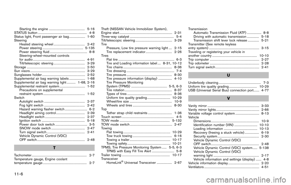
11-6
Starting the engine ............................................. 5-16
STATUS button ............................................................. 4-8
Status light, Front passenger air bag .................... 1-60
Steering Heated steering wheel ....................................... 2-42
Power steering ................................................... 5-135
Power steering fluid ............................................... 8-8
Steering-wheel-mounted controls
for audio ................................................................. 4-91
Tilt/telescopic steering ....................................... 3-29
Storage ......................................................................... 2-50
Sun visors ..................................................................... 3-29
Sunglasses holder ...................................................... 2-52
Supplemental air bag warning labels .................... 1-68
Supplemental air bag warning light ........... 1-68, 2-16
Supplemental restraint system ................................ 1-52 Precautions on supplemental
restraint system .................................................... 1-52
Switch Autolight switch ................................................... 2-37
Fog light switch ................................................... 2-42
Hazard warning flasher switch ............................ 6-2
Headlight aiming control .................................... 2-39
Headlight switch .................................................. 2-37
Ignition switch ...................................................... 5-18
Power door lock switch ........................................ 3-5
SNOW mode switch .......................................... 2-47
Turn signal switch ................................................ 2-41
Vehicle Dynamic Control (VDC)
OFF switch ............................................................ 2-48
T
Tachometer ..................................................................... 2-7
Temperature gauge, Engine coolant
temperature gauge ....................................................... 2-7 Theft (NISSAN Vehicle Immobilizer System) ,
Engine start .................................................................. 2-31
Three-way catalyst ....................................................... 5-4
Tilt/telescopic steering .............................................. 3-29
Tire
Pressure, Low tire pressure warning light .... 2-15
Tire replacement indicator ................................. 2-26
Tires Flat tire ...................................................................... 6-3
Tire and Loading information label .... 8-31, 10-12
Tire chains ............................................................. 8-36
Tire dressing ............................................................ 7-4
Tire pressure ......................................................... 8-30
Tire pressure information (display) ................. 4-10
Tire Pressure Monitoring
System (TPMS) ............................................. 5-5, 6-3
Tire rotation ........................................................... 8-37
Types of tires ........................................................ 8-36
Uniform tire quality grading ............................. 10-29
Wheel/tire size ..................................................... 10-9
Wheels and tires ................................................. 8-30
To p Tether strap child restraints .............................. 1-36
Touch screen ................................................................. 4-5
TOW mode ............................................................... 5-132
TOW mode switch ..................................................... 2-47
Towing Flat towing ........................................................... 10-29
Tow truck towing ................................................. 6-16
Towing a trailer ................................................... 10-17
Towing safety ...................................................... 10-21
TPMS, Tire Pressure Monitoring System ...... 5-5, 6-3 TPMS with Easy Fill Tire Alert ............................ 5-8
Trailer towing ............................................................ 10-17
Transceiver HomeLink
�ŠUniversal Transceiver ................... 2-67 Transmission
Automatic Transmission Fluid (ATF) .................. 8-8
Driving with automatic transmission ............... 5-18
Transmission shift lever lock release .............. 5-21
Transmitter (See remote keyless
entry system) ............................................................... 3-15
Traveling or registering your vehicle in
another country ........................................................ 10-10
Trip computer .............................................................. 2-27
Trip odometer .............................................................. 2-28
Turn signal switch ....................................................... 2-41
U
Underbody cleaning ..................................................... 7-3
Uniform tire quality grading ................................... 10-29
USB (Universal Serial Bus) connection port ....... 4-77
V
Vanity mirror ................................................................. 3-33
Vanity mirror lights ...................................................... 2-66
Variable voltage control system .............................. 8-13
Vehicle Dimensions ............................................................ 10-9
Identification number (VIN) ............................. 10-10
Loading information .......................................... 10-13
Recovery (freeing a stuck vehicle) .................. 6-19
Security system .................................................... 2-30
Vehicle Dynamic Control (VDC)
OFF switch ............................................................ 2-48
Vehicle Dynamic Control (VDC) system ...... 5-138
Vehicle Dynamic Control (VDC)
warning light ......................................................... 2-17
Vehicle information and settings (display) ....... 4-8
Vehicle information display ....................................... 2-20
Ventilators ..................................................................... 4-51