2017 MITSUBISHI OUTLANDER tire size
[x] Cancel search: tire sizePage 193 of 521

Adaptive Cruise Control System (ACC) (if so equipped) 5-112 Features and controls
5
N00581500027
There are two ways to increase the set speed. The set speed will increase by 1 mph (1 km/h) every time you push up the “RES +” switch while the ACC is activated. If youhold the switch pushed up, the set speed increases in 5 mph (5 km/h) increments.
• When the height of a vehicle in front is extremely low or the road clearance ofthe vehicle is extremely high.• When driving on a r
oad with alternating
up and down surfaces.• When driving on a curve.• When driving on a bumpy or rough road.• When driving in a tunnel.• When driving in construction zones.• When the rear of your vehicle is weighed down with the weight of passengers and luggage• For up to two minutes after starting driv-ing.• When driving in curved sections of roadincluding their entrance/outlet or run-ning beside a closed lane in a traffic work or similar zone.• When the surface of th
e sensor is covered
with dirt, snow, ice, etc.• When a front vehicle or an oncomingvehicle is splashing wa
ter, snow or dirt.
WA R N I N G
• When driving on
a winding road.
Never use the ACC in the following situa- tions:• In heavy traffic.• On winding roads.• On slippery roads, such as icy, snow-cov-ered or dirt roads.• In adverse weather conditions, such asrain, snow or sand storms, etc.• On steep downslopes.• When the inclination of a road fre-quently changes.• When the approach alarm frequentlysounds.• When your vehicle is towed or is towinganother vehicle.• When your vehicle is on a chassis dyna-mometer or free rollers.• When tire inflation pressures are notadequate.• When the temporary sp
are tire is being
used.• When the radar sensor and/or its sur-rounding area are damaged or deformed.WA R N I N G
CAUTION To maintain proper performance of the ACC:• Always clean the surface of the radar sen- sor.• Avoid impacting the radar sensor or its sur-rounding area.• Do not put a sticker on the radar sensor orits surrounding area.• Do not paint the radar sensor.• Do not install a grill guard.• Do not modify the radar sensor or its sur- rounding area.• Always use tires of the same size, sametype, and same brand, and which have no significant wear differences.• Do not modify the vehicle’s suspension.
To increase the set speed
By using the “RES +” switch:
BK0239700US.book 112 ページ 2016年6月16日 木曜日 午前10時58分
Page 206 of 521

Forward Collision Mitigation System (FCM) (if so equipped)
Features and controls 5-125
5
N00593400036
The sensor (A) is located inside the wind- shield as shown in the illustration. The sensor is shared in the following sys-tems: FCM Lane Departure Warning (LDW) Automatic high beam system
NOTE
If the sensor or its surrounding area becomes extremely high temperature when parkingthe vehicle under a blazing sun, the “FCMSERVICE REQUIRED” message may appear. After the temperature of the sensor or its sur-rounding area has been in range, if the mes- sage remains even afte
r restarting the engine,
please contact an au
thorized Mitsubishi
Motors dealer.
Handling of the sensor
CAUTION To maintain proper performance of the FCM, LDW and Automatic high beam system;• Always keep clea
n the windshield.
If the inside of the windshield where the sensor is installed be
comes dirty or fogged,
contact an authorized Mitsubishi Motors dealer.• Do not apply an impact or load on the sen-sor or its surrounding area.
• Do not put anything including a sticker or film on the windshield in front of or sur-rounding the area of the sensor.• Do not attempt to deta
ch or disassemble the
sensor.• If the windshield is misted, remove the mistfrom the windshield by using the defogger switch.• Maintain the wiper blades in good condi-tion. Refer to “Wiper blades” on page 9-44.When replacing the wi
per blades, use only
Mitsubishi Motors Genui
ne parts or equiva-
lent.• Do not dirty or da
mage the sensor.
• Do not spray glass cleaner on the sensor. Also, do not spill liqui
d, such as a bever-
age, to the sensor.• Do not install an electronic device, such asantenna, or a device th
at emits strong elec-
tric waves, near the sensor.• Always use tires of the same size, sametype and same brand,
and which have no
significant wear differences.• Do not modify the vehicle’s suspensions.CAUTION
BK0239700US.book 125 ページ 2016年6月16日 木曜日 午前10時58分
Page 225 of 521

Tire pressure monitoring system 5-144 Features and controls
5
Each tire, including the spare (if provided), should be checked monthly when cold and inflated to the inflation pressure recom-mended by the vehicle manufacturer on the vehicle placard or tire
inflation pressure label.
(If your vehicle has tires of a different sizethan the size indicated on the vehicle placard or tire inflation pressure label, you should determine the proper ti
re inflation pressure
for those tires.) As an added safety feature, your vehicle has been equipped with a tire pressure monitoringsystem (TPMS) that illuminates a low tire pressure telltale when
one or more of your
tires is significant
ly under-inflated.
Accordingly, when the low tire pressure tell- tale illuminates, you should stop and check your tires as soon as possible, and inflatethem to the proper pressure. Driving on a sig- nificantly under-inflated
tire causes the tire to
overheat and can lead
to tire failure.
Under-inflation also reduces fuel efficiency and tire tread life, and may affect the vehi-cle’s handling and stoppi
ng ability. Please
note that the TPMS is
not a substitute for
proper tire maintenance,
and it is the driver’s
responsibility to
maintain corre
ct tire pres-
sure, even if under-inflation has not reached the level to trigger illumination of the TPMSlow tire pressure telltale. Your vehicle has also
been equipped with a
TPMS malfunction indica
tor to indicate when
the system is not operating properly. The TPMS malfunction indicator is combined with the low tire pressure telltale.When the system detects a malfunction, the telltale will flash for approximately one min- ute and then remain c
ontinuously illuminated.
This sequence will c
ontinue upon subsequent
vehicle start-ups as long as the malfunction exists.When the malfunction indicator is illumi- nated, the system may not
be able to detect or
signal low tire pr
essure as intended.
TPMS malfunctions may
occur for a variety
of reasons, including the installation of replacement or alternate tires or wheels on thevehicle that prevent the TPMS from function- ing properly. Always
check the TPMS mal-
function telltale after replacing one or moretires or wheels on your vehicle to ensure that the replacement or alternate tires and wheels
allow the TPMS to continue to function prop- erly.
N00532801511
1. If the tire pressure monitoring systemwarning light illuminates, avoiding hard braking, sharp steering maneuvers and high speeds. You should stop and adjust the tires to the proper inflation pressure as soon as possible. Adjust the spare tire atthe same time. Refer to “Tires” on page 9-15.
NOTE
In addition, the warni
ng display is displayed
on the information screen in the multi-infor-mation display.
If the warning light / display illuminates while driving
NOTE
In addition, the warni
ng display is displayed
on the information screen in the multi-infor- mation display. When inspecting or adjusting the tire pres- sure, do not apply excessive force to the valve stem to
avoid breakage.
After inspecting or adjusting the tire pres- sure, always reinstall the valve cap on thevalve stem. Without the valve cap, di
rt or moisture could
get into the valve, resulting in damage to thetire inflation pressure sensor. Do not use metal valve caps, which may cause a metal reaction,
resulting in corrosion
and damage of the tire
inflation pressure sen-
sors.
BK0239700US.book 144 ページ 2016年6月16日 木曜日 午前10時58分
Page 229 of 521

Parking sensors (Front/Rear) (if so equipped) 5-148 Features and controls
5
“Normal mode” and “Tow
ing hitch mode” for
a vehicle equipped with a towing hitch can beselected.
The detection areas are within approximately 24 inches (60 cm) (A) from the front and cor-ner sensors and 49 inches (125 cm) (B) from the back sensors.
• When the ambient temp
erature has rapidly
changed.• When the sensor is frozen.• When the system detects ultrasonic noise,such as the noise from motorcycle engines, brakes, radios, pouring rain, splashing water or tire chains.• When the sensor is extremely hot or cold(after the vehicle has
been parked for a long
period of time under
a blazing sun or in
cold weather).• When the vehicle is driven on a rough roadincluding a bumpy, gravel, hilly, or grassy surface.• When the vehicle is too close to an object.• Immediately after the engine switch is turned on.
The parking sensors may not properly detect certain objects including;• A thin object such as a wire net or rope.• An object that absorbs ultrasonic sound waves, such as snow.• An object with sharp angles.• An object with a sm
ooth surface, such as
glass.• A low height object such as a curb. If the bumper has experienced an impact, the sensor area may have
damage and the park-
ing sensors may not f
unction properly. Have
the vehicle inspected at an authorized Mit- subishi Motors dealer or a repair facility of your choice.CAUTION
Detection areas
WA R N I N G The detection areas described below are for reference only. The actual detectionareas may vary depend
ing on the shape,
size and position of
the object being
detected. Certain objects may not bedetected, even if the object is within the detection area described below. Also false alerts may sound de
pending on the sur-
rounding environment.
Normal mode
BK0239700US.book 148 ページ 2016年6月16日 木曜日 午前10時58分
Page 373 of 521

Loading information 6-8 Driving safety
6
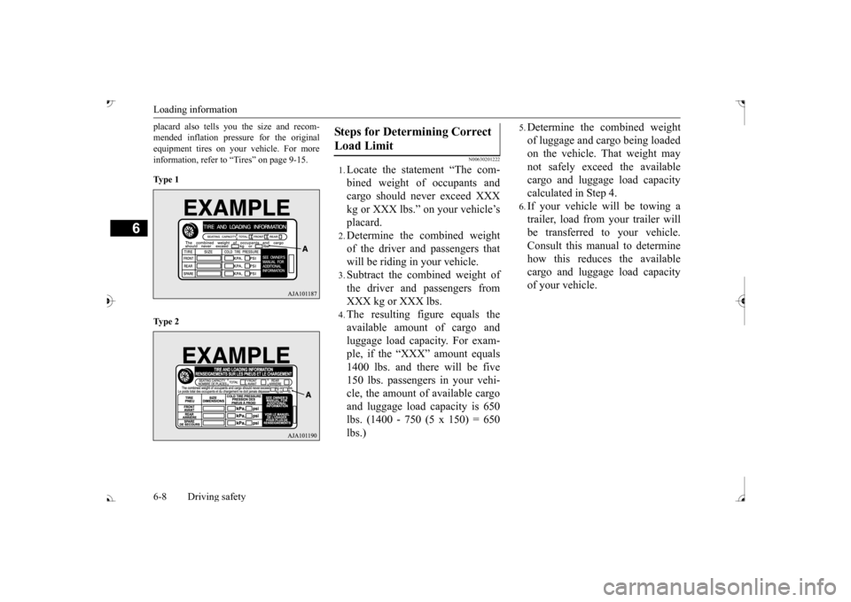
placard also tells you the size and recom- mended inflation pressure for the originalequipment tires on your vehicle. For more information, refer to “Tires” on page 9-15. Ty p e 1 Ty p e 2
N00630201222
1.Locate the statement “The com- bined weight of occupants and cargo should never exceed XXX kg or XXX lbs.” on your vehicle’splacard.2.Determine the combined weightof the driver and passengers thatwill be riding in your vehicle.3.Subtract the combined weight ofthe driver and passengers fromXXX kg or XXX lbs.4.The resulting figure equals theavailable amount of cargo andluggage load capacity. For exam- ple, if the “XXX” amount equals 1400 lbs. and there will be five150 lbs. passengers in your vehi- cle, the amount of available cargo and luggage load
capacity is 650
lbs. (1400 - 750 (5 x 150) = 650lbs.)
5.Determine the combined weightof luggage and cargo being loaded on the vehicle. That weight may not safely exceed the availablecargo and luggage load capacity calculated in Step 4.6.If your vehicle will be towing a trailer, load from your trailer will be transferred to your vehicle. Consult this manual to determinehow this reduces the available cargo and luggage load capacity of your vehicle.
Steps for Determining Correct Load Limit
BK0239700US.book 8 ページ 2016年6月16日 木曜日 午前10時58分
Page 446 of 521

How to change a tire
For emergencies 8-11
8
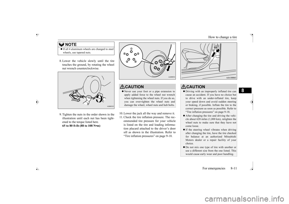
8. Lower the vehicle slowly until the tire touches the ground, by rotating the wheel nut wrench counterclockwise. 9. Tighten the nuts in the order shown in the illustration until each
nut has been tight-
ened to the torque listed here.65 to 80 ft-lb (88 to 108 N•m)
10. Lower the jack all the way and remove it. 11. Check the tire inflation pressure. The rec-
ommended tire pressure for your vehicleis listed on the tire
and loading informa-
tion placard attached to the driver’s door sill as shown in the illustration. Refer to“Tire inflation pressures” on page 9-18.
NOTE
If all 4 aluminum wheels are changed to steel wheels, use tapered nuts.
CAUTION Never use your foot or a pipe extension to apply added force to the wheel nut wrenchwhen tightening the wheel nuts. If you do so, you can over-tighten the wheel nuts and damage the wheel, wheel nuts and hub bolts.
CAUTION Driving with an imprope
rly inflated tire can
cause an accident. If
you have no choice but
to drive with an under-inflated tire, keep your speed down and avoid sudden steering or braking, if possible. Inflate the tire to thecorrect pressure as s
oon as possible. Refer to
“Tire inflation pressures” on page 9-18. After changing the tire
and driving the vehi-
cle about 620 miles (1,000 km), retighten the wheel nuts to make sure
that they have not
come loose. If the steering wheel vibrates when driving after changing the tire, have the tire checked for balance at an authorized Mitsubishi Motors dealer or a repair facility of yourchoice. Do not mix one type of tire with another or use a different size from the one listed. This would cause ea
rly wear and poor handling.
BK0239700US.book 11 ページ 2016年6月16日 木曜日 午前10時58分
Page 469 of 521

Tires 9-16 Vehicle care and maintenance
9
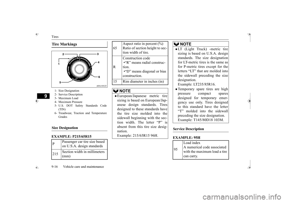
EXAMPLE: P215/65R15
EXAMPLE: 95H
Tire Markings 1- Size Designation 2- Service Description 3- Maximum Load 4- Maximum Pressure5- U.S. DOT Safety Standards Code
(TIN)
6- Treadwear, Traction and Temperature
Grades
Size Designation P
Passenger car tire size based on U.S.A. design standards
215
Section width in millimeters (mm)
65
Aspect ratio in percent (%) Ratio of section height to sec-tion width of tire.
R
Construction code •“R” means radial construc- tion. •“D” means diagonal or bias construction.
15 Rim diameter in inches (in)
NOTE
European/Japanese metric tire sizing is based on European/Jap- anese design standards. Tires designed to these standards havethe tire size molded into the sidewall beginning with the sec- tion width. The letter “P” isabsent from this tire size desig- nation. Example: 215/65R15 96H.
LT (Light Truck) -metric tiresizing is based on U.S.A. design standards. The size designation for LT-metric tires is the same asfor P-metric tires except for the letters “LT” that are molded into the sidewall preceding the sizedesignation. Example: LT235/85R16.Temporary spare tires are highpressure compact spares designed for temporary emer-gency use only. Tires designed to this standard have the letter “T” molded into the sidewallpreceding the size designation. Example: T145/80D18 103M.
Service Description 95
Load index A numerical code associated with the maximum load a tire can carry.NOTE
BK0239700US.book 16 ページ 2016年6月16日 木曜日 午前10時58分
Page 470 of 521

Tires
Vehicle care and maintenance 9-17
9
Maximum load indicates the maxi- mum load this tire is designed to carry.
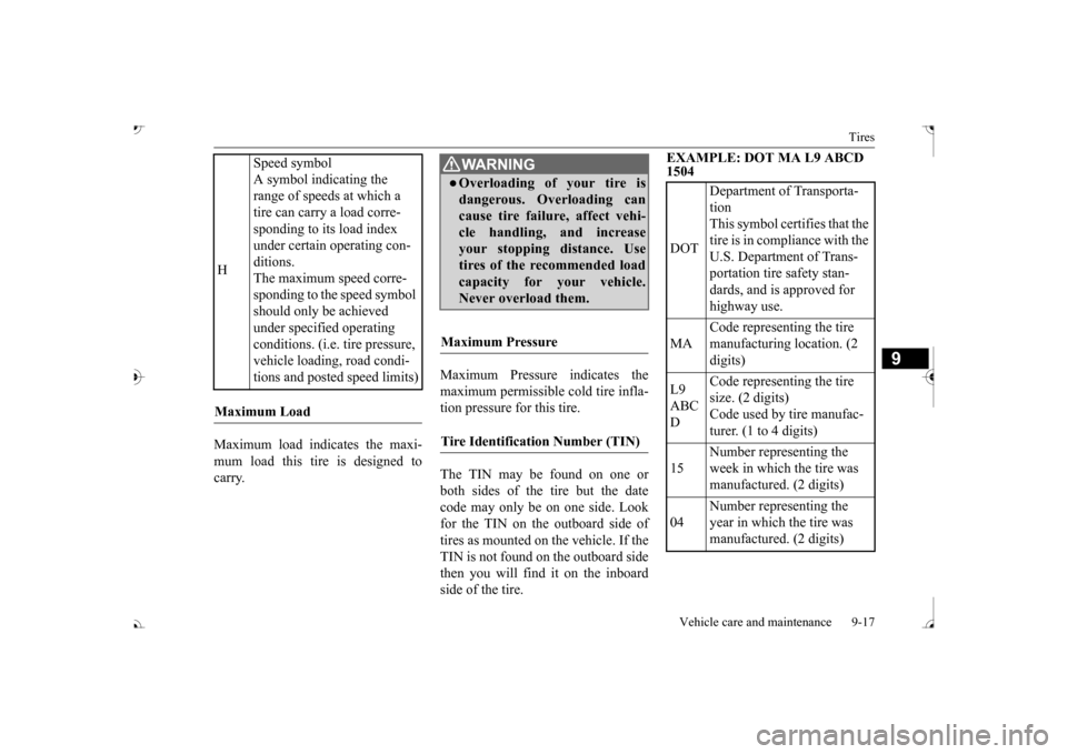
Maximum Pressure indicates the maximum permissible cold tire infla- tion pressure for this tire. The TIN may be found on one or both sides of the tire but the datecode may only be on one side. Look for the TIN on the outboard side of tires as mounted on the vehicle. If theTIN is not found on the outboard side then you will find it on the inboard side of the tire.
EXAMPLE: DOT MA L9 ABCD 1504
H
Speed symbol A symbol indicating the range of speeds at which a tire can carry a load corre- sponding to its load index under certain operating con- ditions. The maximum speed corre-sponding to the speed symbol should only be achieved under specified operating conditions. (i.e. tire pressure, vehicle loading, road condi- tions and posted speed limits)
Maximum Load
WA R N I N GOverloading of your tire is dangerous. Overloading can cause tire failure, affect vehi- cle handling, and increaseyour stopping distance. Use tires of the recommended load capacity for your vehicle.Never overload them.
Maximum Pressure Tire Identification Number (TIN)
DOT
Department of Transporta- tion This symbol certifies that the tire is in compliance with the U.S. Department of Trans- portation tire safety stan- dards, and is approved for highway use.
MA
Code representing the tire manufacturing location. (2 digits)
L9 ABC D
Code representing the tire size. (2 digits) Code used by tire manufac-turer. (1 to 4 digits)
15
Number representing the week in which the tire was manufactured. (2 digits)
04
Number representing the year in which the tire was manufactured. (2 digits)
BK0239700US.book 17 ページ 2016年6月16日 木曜日 午前10時58分