2017 MITSUBISHI OUTLANDER heater
[x] Cancel search: heaterPage 37 of 521
Second row seats 4-8 Seat and restraint systems
4
N00435601463
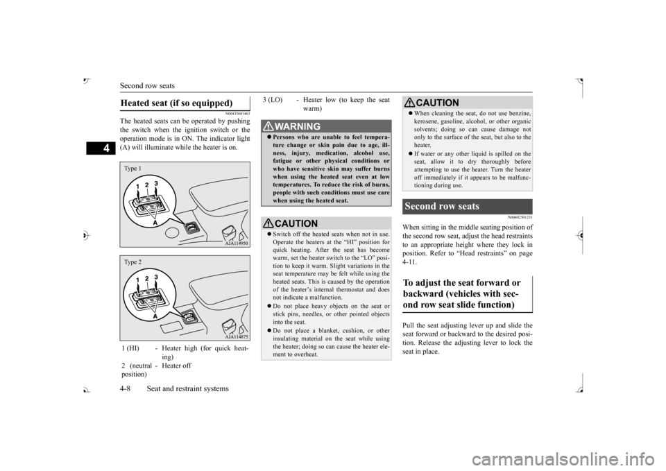
The heated seats can
be operated by pushing
the switch when the ignition switch or the operation mode is in ON. The indicator light(A) will illuminate while the heater is on.
N00402501231
When sitting in the mi
ddle seating position of
the second row seat, adjust the head restraints to an appropriate height where they lock inposition. Refer to “Hea
d restraints” on page
4-11. Pull the seat adjusting lever up and slide the seat forward or backward to the desired posi- tion. Release the adjusting lever to lock the seat in place.
Heated seat (if so equipped) 1 (HI) - Heater high (for quick heat-
ing)
2 (neutral position)
- Heater off
Type 1Type 2
3 (LO) - Heater low (to keep the seat
warm)
WA R N I N G Persons who are unable to feel tempera- ture change or skin
pain due to age, ill-
ness, injury, medication, alcohol use,fatigue or other phys
ical conditions or
who have sensitive sk
in may suffer burns
when using the heated seat even at lowtemperatures. To reduce the risk of burns, people with such conditions must use care when using the heated seat.CAUTION Switch off the heated seats when not in use. Operate the heaters at the “HI” position for quick heating. After the seat has becomewarm, set the heater switch to the “LO” posi- tion to keep it warm. Sl
ight variations in the
seat temperature may be felt while using theheated seats. This is caused by the operation of the heater’s internal thermostat and does not indicate a malfunction. Do not place heavy obj
ects on the seat or
stick pins, needles, or
other pointed objects
into the seat. Do not place a blanket,
cushion, or other
insulating material on the seat while usingthe heater; doing so can
cause the heater ele-
ment to overheat.
When cleaning the seat, do not use benzine, kerosene, gasoline, alc
ohol, or other organic
solvents; doing so can cause damage notonly to the surface of the seat, but also to the heater. If water or any other li
quid is spilled on the
seat, allow it to dry thoroughly before attempting to use the heater. Turn the heateroff immediately if it
appears to be malfunc-
tioning during use.
Second row seats To adjust the seat forward or backward (vehicles with sec-ond row seat slide function)
CAUTION
BK0239700US.book 8 ページ 2016年6月16日 木曜日 午前10時58分
Page 144 of 521
Ignition switch
Features and controls 5-63
5
N00549301260
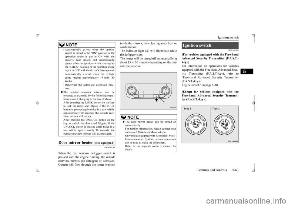
When the rear window defogger switch is pressed with the engine running, the outside rearview mirrors are defogged or defrosted. Current will flow thr
ough the heater element
inside the mirrors, thus clearing away frost or condensation.The indicator light (A) will illuminate while the defogger is on. The heater will be turned off automatically inabout 15 to 20 minutes depending on the out- side temperature.
N00512401696
[For vehicles equipped with the Free-handAdvanced Security Tr
ansmitter (F.A.S.T.-
key).]For information on operations for vehicles equipped with the Free-hand Advanced Secu- rity Transmitter (F.A
.S.T.-key), refer to
“Free-hand Advanced
Security Transmitter
(F.A.S.T.-key): Engine switch” on page 5-18. [Except for vehicles equipped with the Free-hand Advanced Security Transmit- ter (F.A.S.T.-key).]
• Automatically extend when the ignition switch is turned to the “ON” position or theoperation mode is put in ON with thedriver’s door closed, and automatically retract when the ignition switch is turned to the “LOCK” position or the operation modeis put in OFF with the driver’s door opened. • Automatically extend when the vehicle speed reaches approximately 19 mph (30 km/h). • Deactivate the automatic extension func- tion.
The outside rearvi
ew mirrors can be
retracted or extended
by the following opera-
tions, even if changing to the any of above.After pressing the LOCK
button on the key
to lock the doors and liftgate, if the LOCK button is pressed again twice in a row withinapproximately 30 seconds
, the outside rear-
view mirrors will retract. After pressing the
UNLOCK button on the
key to unlock the doors and liftgate, if the UNLOCK button is pressed again twice in a row within approximately 30 seconds, theoutside rearview mirro
rs will extend again.
Door mirror heater
(if so equipped)
NOTE
The door mirror heater can be turned on automatically.For further informati
on, please contact your
authorized Mitsubishi Motors dealer. On vehicles equipped
with Mitsubishi Multi-
Communication System, screen operations can be used to ma
ke the adjustment.
Refer to the separate
owner’s manual for
details.
Ignition switch Type 1 Type 2
BK0239700US.book 63 ページ 2016年6月16日 木曜日 午前10時58分
Page 319 of 521
Electric rear window defogger switch 5-238 Features and controls
5
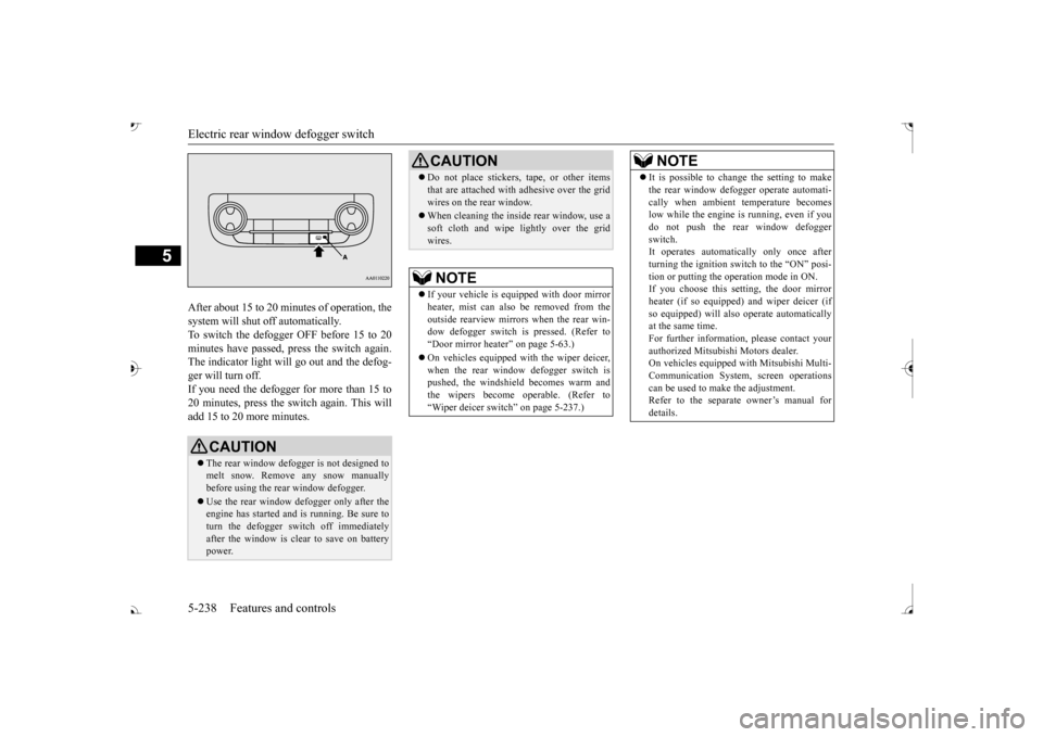
After about 15 to 20 minutes of operation, the system will shut off automatically.To switch the defogger OFF before 15 to 20 minutes have passed,
press the switch again.
The indicator light will
go out and the defog-
ger will turn off. If you need the defogger for more than 15 to 20 minutes, press the switch again. This willadd 15 to 20 more minutes.
CAUTION The rear window defogge
r is not designed to
melt snow. Remove any snow manually before using the rear window defogger. Use the rear window defogger only after the engine has started and
is running. Be sure to
turn the defogger switch off immediatelyafter the window is clea
r to save on battery
power.
Do not place stickers,
tape, or other items
that are attached with adhesive over the gridwires on the rear window. When cleaning the inside
rear window, use a
soft cloth and wipe lightly over the gridwires.NOTE
If your vehicle is e
quipped with door mirror
heater, mist can also be removed from the outside rearview mirror
s when the rear win-
dow defogger switch is
pressed. (Refer to
Page 320 of 521
Heated steering wheel switch (if so equipped)
Features and controls 5-239
5
N00589100032
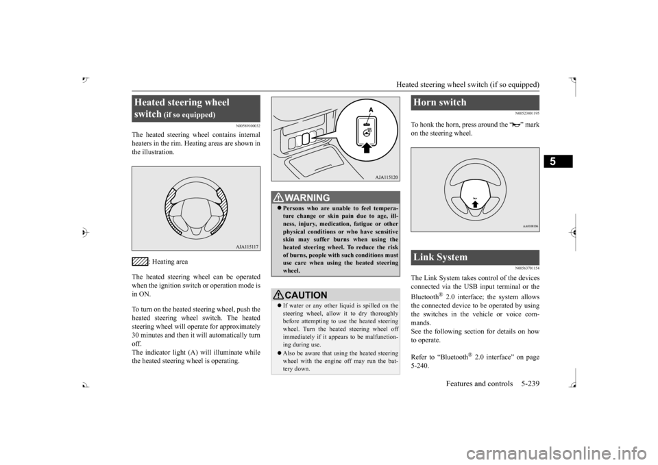
The heated steering wh
eel contains internal
heaters in the rim. Heating areas are shown in the illustration.
: Heating area
The heated steering wheel can be operated when the ignition switch or operation mode is in ON. To turn on the heated steering wheel, push the heated steering wheel switch. The heated steering wheel will ope
rate for approximately
30 minutes and then it
will automatically turn
off. The indicator light (A) will illuminate while the heated steering wheel is operating.
N00523801195
To honk the horn, press around the “ ” markon the steering wheel.
N00563701154
The Link System takes control of the devicesconnected via the USB input terminal or the Bluetooth
® 2.0 interface; the system allows
the connected device to be operated by using the switches in the vehicle or voice com-mands. See the following section for details on how to operate. Refer to “Bluetooth
® 2.0 interface” on page
5-240.
Heated steering wheel switch
(if so equipped)
Persons who are unable
to feel tempera-
ture change or skin
pain due to age, ill-
ness, injury, medicati
on, fatigue or other
physical conditions or
who have sensitive
skin may suffer burns when using theheated steering wheel. To reduce the risk of burns, people with such conditions must use care when using the heated steeringwheel.CAUTION If water or any other li
quid is spilled on the
steering wheel, allow it to dry thoroughly before attempting to use the heated steering wheel. Turn the heated steering wheel offimmediately if it appe
ars to be malfunction-
ing during use. Also be aware that us
ing the heated steering
wheel with the engine off may run the bat- tery down.
Horn switch Link System
BK0239700US.book 239 ページ 2016年6月16日 木曜日 午前10時58分
Page 372 of 521
Loading information Driving safety 6-7
6
installed options, and
the tongue weight of
the trailer, if any, being towed. The tire andloading information placard located on the driver’s door sill of your vehicle will show how much weight it may properly carry. It is important to famil
iarize yourself with the
following terms before loading your vehicle: Vehicle maximum load on the tire: load on an individual tire that is determined by distributing to each axle its share of the maximum loaded vehicle weight anddividing by two. Vehicle normal load on the tire: load on an individual tire that is determined by dis-tributing to each axle its share of the curb weight, accessory weight, and normal occupant weight and dividing by two. Maximum loaded vehicle weight: the sum of - (a) Curb weight;(b) Accessory weight; (c) Vehicle capacity weight; and (d) Production options weight.
Curb weight: the weight of a motor vehi- cle with standard equipment including themaximum capacity of
fuel, oil, and cool-
ant. Accessory weight: the combined weight (in excess of those st
andard items which
may be replaced) of automatic transaxle, power steering, power brakes, power win-dows, power seats, radio, and heater, to the extent that these items are available as factory- installed equipment (whether installed or not). Vehicle capacity weight: the rated cargo and luggage load plus 150 lbs (68 kg) * times the vehicle’s designated seating capacity. Production options weight: the combined weight of those installed regular produc- tion options weighing over 5 lbs (2.3 kg)in excess of those standard items which they replace, not prev
iously considered in
curb weight or accessory weight, includ-ing heavy duty brakes,
ride levelers, roof
rack, heavy duty battery, and special trim. Normal occupant weight: 150 lbs (68 kg) * times the number of
specified occupants
(3 in the case of your vehicle) Occupant distribution:
Occupant distribu-
tion within the passenger compartment (In your vehicle the distribution is 2 in front, 1 in second row seat)
N00630101407
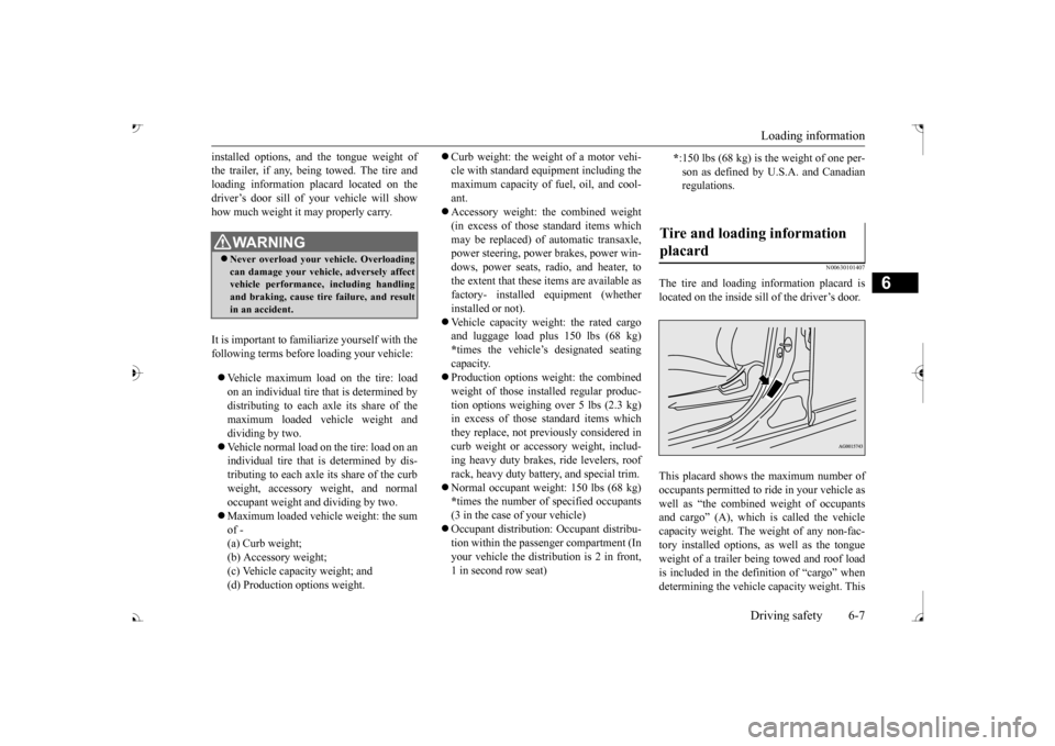
The tire and loading information placard islocated on the inside sill of the driver’s door. This placard shows the maximum number of occupants permitted to
ride in your vehicle as
well as “the combined
weight of occupants
and cargo” (A), which
is called the vehicle
capacity weight. The weight of any non-fac- tory installed options, as well as the tongueweight of a trailer being towed and roof load is included in the defi
nition of “cargo” when
determining the vehicle
capacity weight. This
WA R N I N GNever overload your ve
hicle. Overloading
can damage your vehicl
e, adversely affect
vehicle performance, including handling and braking, cause tire failure, and resultin an accident.
* :150 lbs (68 kg) is the weight of one per- son as defined by U.
S.A. and Canadian
regulations.
Tire and loading information placard
BK0239700US.book 7 ページ 2016年6月16日 木曜日 午前10時58分
Page 390 of 521
Dual-zone automatic climat
e control air conditioner Comfort controls 7-7
7
N00737001448
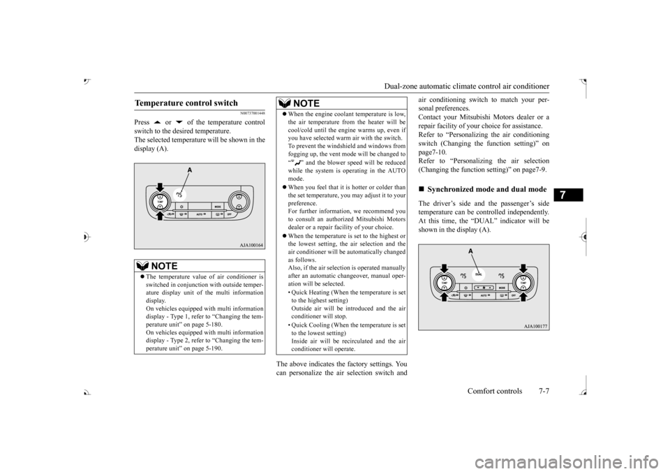
Press or of the temperature control switch to the desired temperature. The selected temperature will be shown in the display (A).
The above indicates the
factory settings. You
can personalize the air
selection switch and
air conditioning switch to match your per- sonal preferences.Contact your Mitsubishi
Motors dealer or a
repair facility of your
choice for assistance.
Refer to “Personalizi
ng the air conditioning
switch (Changing the function setting)” on page7-10. Refer to “Personalizing the air selection(Changing the function setting)” on page7-9. The driver’s side and the passenger’s side temperature can be controlled independently.At this time, the “
DUAL” indicato
r will be
shown in the display (A).
Temperature control switch
NOTE
The temperature value
of air conditioner is
switched in conjunction
with outside temper-
ature display unit of the multi informationdisplay. On vehicles equipped with multi information display - Type 1, refer to “Changing the tem-perature unit” on page 5-180. On vehicles equipped with multi information display - Type 2, refer to “Changing the tem-perature unit” on page 5-190.
When the engine coolan
t temperature is low,
the air temperature from the heater will becool/cold until the engi
ne warms up, even if
you have selected warm
air with the switch.
To prevent the windshield and windows from fogging up, the vent mode will be changed to “ ” and the blower speed will be reduced while the system is operating in the AUTO mode. When you feel that it is hotter or colder than the set temperature, you may adjust it to yourpreference. For further information, we recommend you to consult an authorized Mitsubishi Motorsdealer or a repair fa
cility of your choice.
When the temperature is set to the highest or the lowest setting, the air selection and the air conditioner will be automatically changed as follows.Also, if the air select
ion is operated manually
after an automatic ch
angeover, manual oper-
ation will be selected. • Quick Heating (When th
e temperature is set
to the highest setting)Outside air will be introduced and the air conditioner will stop. • Quick Cooling (When the temperature is set to the lowest setting) Inside air will be reci
rculated and the air
conditioner wi
ll operate.
NOTE
Synchronized mode and dual mode
BK0239700US.book 7 ページ 2016年6月16日 木曜日 午前10時58分
Page 401 of 521
Handling of Discs 7-18 Comfort controls
7
N00715400038
This explains care that should be taken in the handling of discs. Fingerprints or other marks on the read surface of the disc may result in its con-tent being more difficult to read. When holding the disc, grip both edges, or one edge and the center hol
e, in order that the
read surface is not touched. Do not affix paper or stickers, or other- wise damage the disc. Do not forcefully insert a disc if another is already within the de
vice. This can result
in damage to discs, or malfunction. Periodically clean the read surface of the disc. When cleaning,
do not wipe in a cir-
cular motion. Instead, wipe gently out-wards from the center of the disc to the outer edge. New discs may have burring around the outer edge or in the hole in the center. Ensure you check for these. If there are burrs, these may lead to faulty operation,therefore ensure these are removed.
When not using discs, ensure these are kept in cases, and stor
ed out of direct sun-
light. If discs are not going to be used for a long period of time, remove these from theproduct.
In cold environments such as in mid-winter when the interior of the vehicle is cold, turn-ing the heater on and immediately trying to use the product may cause condensation (water droplets) to form on the disc and inter-nal optical components, and this may prevent the product from operating correctly. In these conditions, remo
ve the disc, and wait
a short time before use. Actions such as una
uthorized reproduction,
broadcast, public perfo
rmance, or rental of
discs that comprise other than personal useare prohibited by law.
N00715500026
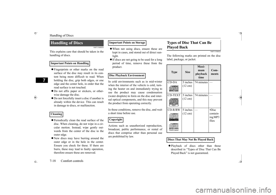
The following marks are printed on the disclabel, package, or jacket. Playback of discs other than those described in “Types of Disc That Can BePlayed Back” is not guaranteed.
Handling of Discs Important Points on Handling Cleaning
Important Points on Storage Disc Playback Environment Copyright
Types of Disc That Can Be Played Back
Ty p e
Size
Maxi- mum playback time
Com-ments
CD-DA 5 inches
(12 cm)
74 minutes —
(12 cm)
74 minutes —
(12 cm)
—•Disc
contain- ing MP3 files
Discs That May Not Be Played Back
BK0239700US.book 18 ページ 2016年6月16日 木曜日 午前10時58分
Page 480 of 521
Fuses
Vehicle care and maintenance 9-27
9
N00954801427
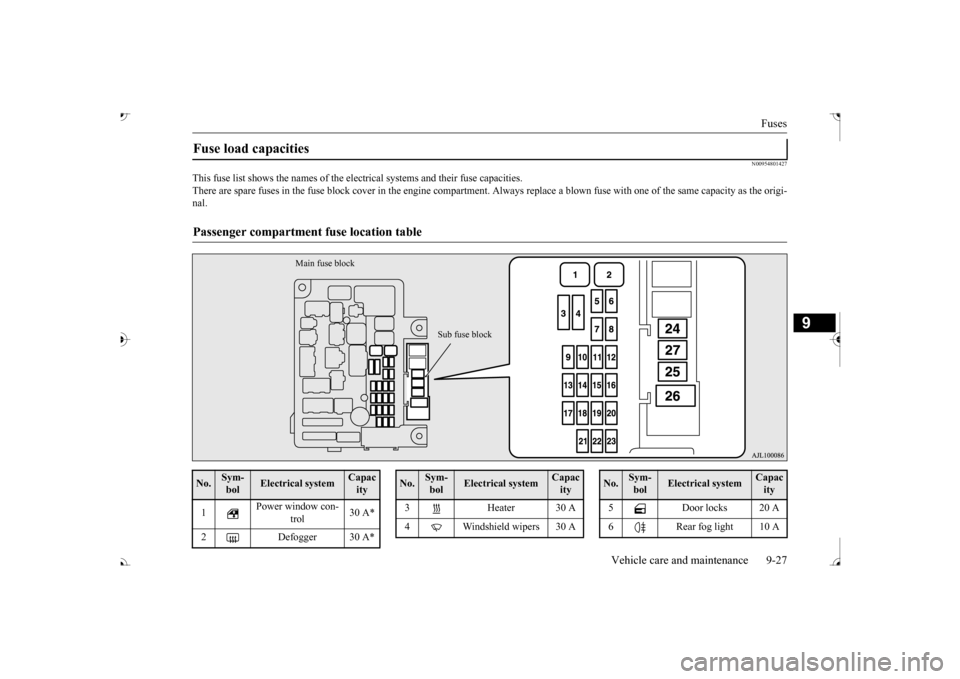
This fuse list shows the names of the elec
trical systems and their fuse capacities.
There are spare fuses in the fuse block cover in the engine compar
tment. Always replace a blown fu
se with one of the same capac
ity as the origi-
nal.Fuse load capacities Passenger compartment
fuse location table
Main fuse block
Sub fuse block
No.
Sym- bol
Electrical system
Capacity
1
Power window con-
trol
30 A*
2 Defogger 30 A*
3 Heater 30 A 4 Windshield wipers 30 ANo.
Sym- bol
Electrical system
Capacity
5 Door locks 20 A 6 Rear fog light 10 ANo.
Sym- bol
Electrical system
Capacity
BK0239700US.book 27 ページ 2016年6月16日 木曜日 午前10時58分