2017 MITSUBISHI OUTLANDER capacity
[x] Cancel search: capacityPage 374 of 521
Loading information Driving safety 6-9
6
NOTE
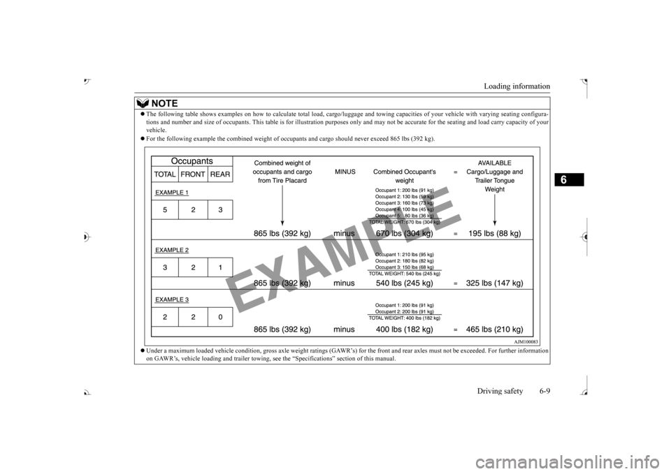
The following table shows examples on how to
calculate tota
l load, cargo/luggage and towing capa
cities of your vehicle with var
ying seating configura-
tions and number and size of occ
upants. This table is for illu
stration purposes only and may not
be accurate for the seating an
d load carry capacity of your
vehicle. For the following example the combined weight of oc
cupants and cargo should ne
ver exceed 865 lbs (392 kg).
Under a maximum loaded vehicle c
ondition, gross axle weight ratings (GAWR’s) for
the front and rear axles must not be exceeded.
For further information
on GAWR’s, vehicle loading and tr
ailer towing, see the “Specifica
tions” section of this manual.
BK0239700US.book 9 ページ 2016年6月16日 木曜日 午前10時58分
Page 375 of 521
Cargo loads 6-10 Driving safety
6
N00629700435 N00630301092
To determine the cargo load capacity for your vehicle, subtract the
weight of all vehicle
occupants from the vehi
cle capacity weight.
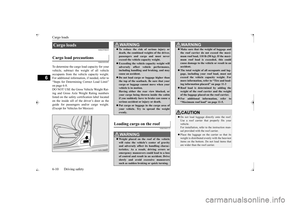
For additional information, if needed, refer to “Steps for Determining Correct Load Limit” on page 6-8. DO NOT USE the Gross Vehicle Weight Rat- ing and Gross Axle Weight Rating numberslisted on the safety certification label located on the inside sill of the driver’s door as the guide for passengers and/or cargo weight.(Except for Vehicles for Mexico)
N00630401123
Cargo loads Cargo load precautions
WA R N I N G To reduce the risk of serious injury or death, the combined weights of the driver,passengers and cargo and must neverexceed the vehicle capacity weight. Exceeding the vehicle capacity weight will adversely affect ve
hicle performance,
including handling and braking, and may cause an accident. Do not load cargo or luggage higher than the top of the seatback. Be sure that yourcargo or luggage cann
ot move when your
vehicle is in motion. Having either the re
ar view blocked, or
your cargo being thrown
inside the cabin
if you suddenly have to brake can cause a serious accident or
injury or death.
Put cargo or luggage in the cargo area of your vehicle. Try to spread the weightevenly.
Loading cargo on the roof
WA R N I N G Weight placed on the
roof of the vehicle
will raise the vehicle’ and adversely affect
its handling charac-
teristics. As a result, driving errors oremergency maneuvers could lead to a loss of control and result in an accident. Drive slowly and avoid excessive maneuverssuch as sudden brak
ing or quick turning.
Make sure that the
weight of luggage and
the roof carrier do not exceed the maxi-mum roof load, 110 lb (50 kg). If the maxi-mum roof load is ex
ceeded, this could
cause damage to the ve
hicle or result in an
accident. The total weight of all occupants and lug- gage, including your r
oof load, must not
exceed the vehicle capacity weight. For more information, refer to “Tire and load- ing information placard” on page 11-3 Roof load is determined by adding the weight of the roof
carrier and the weight
of the luggage placed
on the roof carrier.
For additional information, refer to “Maximum roof load” on page 11-5.CAUTION Do not load luggage directly onto the roof. Use a roof carrier that properly fits your vehicle. For installation, refer to the instruction man-ual provided with the roof carrier. Place the luggage on the carrier so that its weight is distri
buted evenly with the heaviest
items on the bottom. Do not load items that are wider than the roof carrier.WA R N I N G
BK0239700US.book 10 ページ 2016年6月16日 木曜日 午前10時58分
Page 377 of 521
Trailer towing 6-12 Driving safety
6
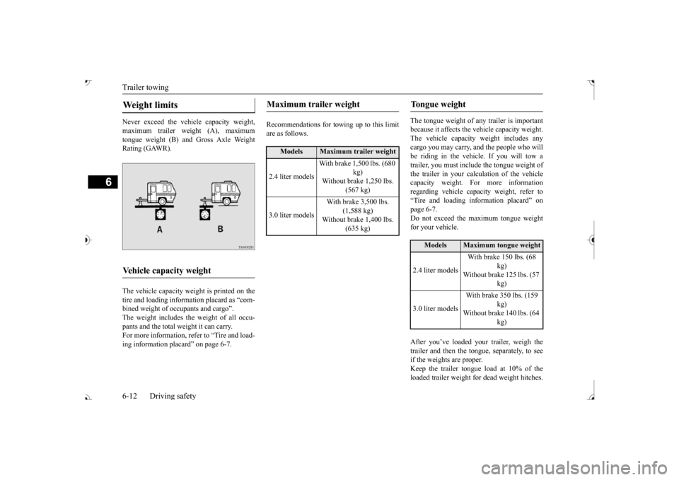
Never exceed the vehicle capacity weight, maximum trailer weight (A), maximum tongue weight (B) and Gross Axle Weight Rating (GAWR). The vehicle capacity weight is printed on the tire and loading inform
ation placard as “com-
bined weight of oc
cupants and cargo”.
The weight includes the weight of all occu- pants and the total weight it can carry.For more information, refer to “Tire and load- ing information plac
ard” on page 6-7.
Recommendations for to
wing up to this limit
are as follows.
The tongue weight of a
ny trailer is important
because it affects the ve
hicle capacity weight.
The vehicle capacity weight includes any cargo you may carry, a
nd the people who will
be riding in the vehi
cle. If you will tow a
trailer, you must include the tongue weight of the trailer in your calculation of the vehiclecapacity weight. For more information regarding vehicle capa
city weight, refer to
“Tire and loading information placard” on page 6-7. Do not exceed the maximum tongue weightfor your vehicle. After you’ve loaded your trailer, weigh the trailer and then the to
ngue, separately, to see
if the weights are proper.Keep the trailer tongue load at 10% of the loaded trailer weight fo
r dead weight hitches.
Weight limits Vehicle capacity weight
Maximum trailer weight
Models
Maximum trailer weight
2.4 liter models
With brake 1,500 lbs. (680
kg)
Without brake 1,250 lbs.
(567 kg)
3.0 liter models
With brake 3,500 lbs.
(1,588 kg)
Without brake 1,400 lbs.
(635 kg)
Tongue weight
Models
Maximum tongue weight
2.4 liter models
With brake 150 lbs. (68
kg)
Without brake 125 lbs. (57
kg)
3.0 liter models
With brake 350 lbs. (159
kg)
Without brake 140 lbs. (64
kg)
BK0239700US.book 12 ページ 2016年6月16日 木曜日 午前10時58分
Page 418 of 521

Listen to Audio Files on a USB Device
Comfort controls 7-35
7
Press the MEDIA key to set USB as the source. The selected source is indicated on the dis- play.
Press the key or key to select the track. This enables selection of the next or previous track. Hold down the 3 key or the 4 key. Fast forward/rewind is possible. Repeat playback, random
playback, and scan
playback are possible. Press the 1RPT key. Repeat playback of the track currently being played.
NOTE
Digital audio players
that support the mass
storage class specific
ations can be con-
nected. For details regarding the types of USB devices that can be c
onnected and the types
of files that can be
played back, refer to
“Types of connectable
devices and supported
file specifications” on page 5-265. Regarding how to c
onnect USB devices,
refer to “How to connect a USB memorydevice” on page 5-263. When connecting a US
B device, use a con-
nection cable. Failur
e to use a connection
cable when connecti
ng may place undue load
on, or damage the USB connector. Set up the device in
order that no unsafe
actions, such as plugging in the connectioncable are taken while driving. When inserting and removing the USB device, for safety’s sa
ke first stop the vehi-
cle. Do not insert other than audio devices into the USB port. Damage to the device or equipment may result. Depending on the status of the USB device, it may take some time unt
il the device is rec-
ognized, or playback starts. Depending on USB device
s, buttons on the
product will not opera
te while the USB
device is connected. USB device specificati
ons and settings may
mean that connection is not possible, or result in differences
in operation or display.
Depending on audio data
in the USB device,
track information may
not be displayed cor-
rectly. Depending on the status of the vehicle and device, the iPod/iPhone
may not play back
after starting
the engine.
Data containing copyri
ght information may
not play back. This product can play back MP3, WMA, and AAC format audio files. Depending on the type of
USB device, usage
may not be possible, or functions that can be used may be restricted. The recommended file system for USB memory is FAT32. The maximum supported capacity for USB memory is 32GB. Operate the USB device containing recorded audio files while conne
cted to this product.
Play Back of Audio Files on a USB Device
NOTE
Select the Track (File) Fast Forward or Rewind Switch Playback Mode Repeat Playback (RPT)
NOTE
Pressing again will cancel.
BK0239700US.book 35 ページ 2016年6月16日 木曜日 午前10時58分
Page 470 of 521
Tires
Vehicle care and maintenance 9-17
9
Maximum load indicates the maxi- mum load this tire is designed to carry.
Maximum Pressure indicates the maximum permissible cold tire infla- tion pressure for this tire. The TIN may be found on one or both sides of the tire but the datecode may only be on one side. Look for the TIN on the outboard side of tires as mounted on the vehicle. If theTIN is not found on the outboard side then you will find it on the inboard side of the tire.
EXAMPLE: DOT MA L9 ABCD 1504
H
Speed symbol A symbol indicating the range of speeds at which a tire can carry a load corre- sponding to its load index under certain operating con- ditions. The maximum speed corre-sponding to the speed symbol should only be achieved under specified operating conditions. (i.e. tire pressure, vehicle loading, road condi- tions and posted speed limits)
Maximum Load
WA R N I N GOverloading of your tire is dangerous. Overloading can cause tire failure, affect vehi- cle handling, and increaseyour stopping distance. Use tires of the recommended load capacity for your vehicle.Never overload them.
Maximum Pressure Tire Identification Number (TIN)
DOT
Department of Transporta- tion This symbol certifies that the tire is in compliance with the U.S. Department of Trans- portation tire safety stan- dards, and is approved for highway use.
MA
Code representing the tire manufacturing location. (2 digits)
L9 ABC D
Code representing the tire size. (2 digits) Code used by tire manufac-turer. (1 to 4 digits)
15
Number representing the week in which the tire was manufactured. (2 digits)
04
Number representing the year in which the tire was manufactured. (2 digits)
BK0239700US.book 17 ページ 2016年6月16日 木曜日 午前10時58分
Page 480 of 521
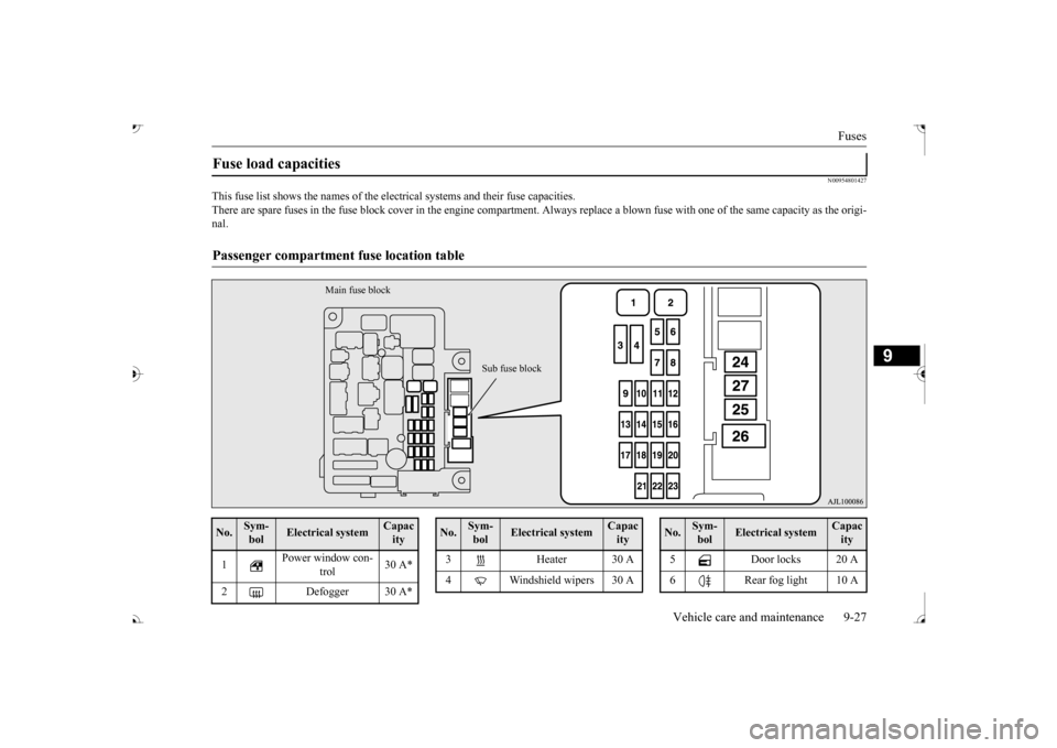
Fuses
Vehicle care and maintenance 9-27
9
N00954801427
This fuse list shows the names of the elec
trical systems and their fuse capacities.
There are spare fuses in the fuse block cover in the engine compar
tment. Always replace a blown fu
se with one of the same capac
ity as the origi-
nal.Fuse load capacities Passenger compartment
fuse location table
Main fuse block
Sub fuse block
No.
Sym- bol
Electrical system
Capacity
1
Power window con-
trol
30 A*
2 Defogger 30 A*
3 Heater 30 A 4 Windshield wipers 30 ANo.
Sym- bol
Electrical system
Capacity
5 Door locks 20 A 6 Rear fog light 10 ANo.
Sym- bol
Electrical system
Capacity
BK0239700US.book 27 ページ 2016年6月16日 木曜日 午前10時58分
Page 481 of 521

Fuses 9-28 Vehicle care and maintenance
9
*: Fusible link Some fuses may not be installed on your vehicle, depending on
the vehicle model
or specifications. The table above show
s the main equip-
ment corresponding to each fuse.
7 12 V power outlet 15 A 8 Rear window wiper 15 A 9 Sunroof 20 A 10 Ignition switch 10 A11 Option 10 A 12
Hazard warning
flasher
15 A
13 4-wheel drive system 10 A 14
Stop lights (Brake lights)
15 A
15 Gauges 10 A 16 SRS airbag 7.5 A 17 Radio 15 A18 Control unit relay 7.5 A 19
Interior lights (Room lights)
15 A
20 Back-up lights 7.5 A 21
Heated outside rearview mirrors
7.5 A
22
Outside rearview
mirrors
10 A
No.
Sym- bol
Electrical system
Capacity
23
Cigarette lighter/ 12 V power outlet
15 A
24
Charge 7.5 A
Heated steering
wheel
15 A
25
Power seat (Driver seat)
30 A*
26 Heated seats 30 A 27
Power seat (Passenger seat)
No.
Sym- bol
Electrical system
Capacity
Engine compartment fuse location table No.
Sym- bol
Electrical sys-
tem
Capacity
SBF1
Air condition- ing condenser fan motor
30 A*
VLC 40 A*
Behind the fuse block cover Main fuse block
BK0239700US.book 28 ページ 2016年6月16日 木曜日 午前10時58分
Page 482 of 521

Fuses
Vehicle care and maintenance 9-29
9
*: Fusible link
SBF2 Starter 30 A* SBF3
Air condition- ing condenser fan motor
30 A*
SBF4
Radiator fan
motor
40 A*
SBF5
Anti-lock brak- ing system
40 A*
SBF6
Electric parking
brake
50 A*
SBF7
Anti-lock brak- ing system
30 A*
BF1 Power liftgate 30 A BF2
Audio system amplifier
30 A
BF3 IOD IOD 30 A BF4 Diesel 30 A F1
Automatic transaxle
20 A
F2 Wiper de-icer 15A F3
Electric parking
brake
7.5 A
F4
Daytime run- ning lights
10 A
No.
Sym- bol
Electrical sys-
tem
Capacity
F5 Front fog lights 15 A F6 Air conditioner 10 A F7
Headlight washer
20 A
F8 Security horn 20 A F9 Horn 10 A F10 ETV 15 AF11 Alternator 7.5 AF12 Engine 7.5 A F13
ENG/POWER 20 A Fuel line heater 25 A
F14 Fuel pump 15 A F15 Ignition coil 10 AF16 ENG/POWER 10 A F17
Headlight (high beam) (left)
10 A
F18
Headlight (high beam) (right)
10 A
No.
Sym- bol
Electrical sys-
tem
Capacity
F19
Head- light (low beam) (left)
LED 20 A
F20
Head- light (low beam) (right)
LED 20 A
F21
Head- light (low beam) (left)
Halo- gen
10 A
F22
Head- light (low beam) (right)
Halo- gen
10 A
F23
Battery current
sensor
7.5 A
#1 — Spare fuse 10 A #2 — Spare fuse 15 A #3 — Spare fuse 20 ANo.
Sym- bol
Electrical sys-
tem
Capacity
BK0239700US.book 29 ページ 2016年6月16日 木曜日 午前10時58分