2017 MITSUBISHI OUTLANDER capacity
[x] Cancel search: capacityPage 25 of 521
Filling the fuel tank 3-4 General information
3
All-wheel drive vehicles: 15.8 gal (60 L) Front-wheel drive vehi
cles: 16.6 gal (63 L)
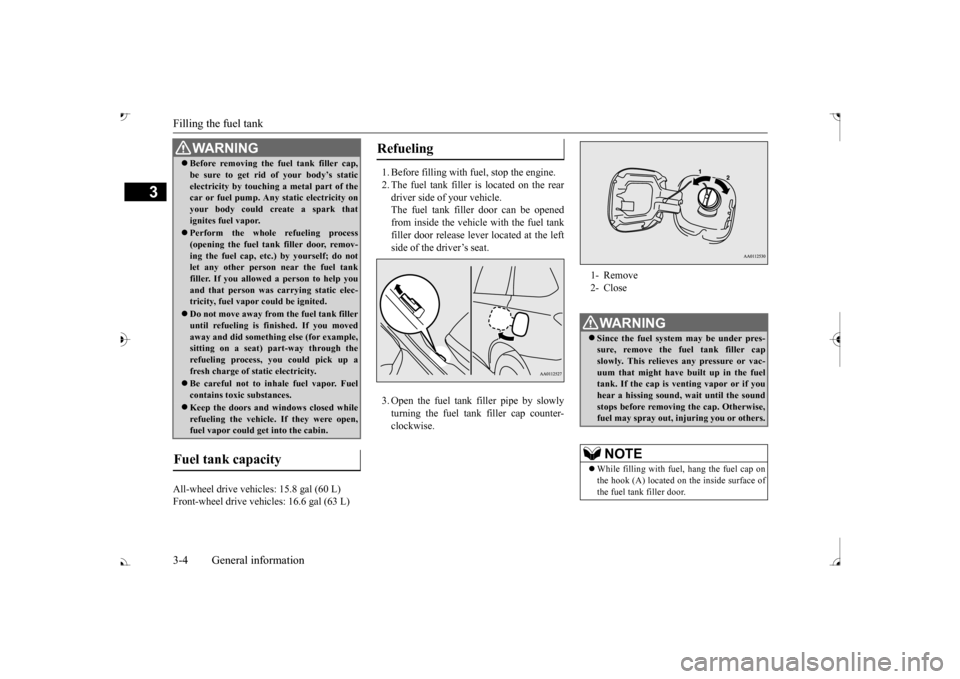
1. Before filling with fuel, stop the engine. 2. The fuel tank filler is located on the rear driver side of your vehicle. The fuel tank filler door can be openedfrom inside the vehicle with the fuel tank filler door release lever located at the left side of the driver’s seat. 3. Open the fuel tank filler pipe by slowly turning the fuel tank filler cap counter- clockwise.
Before removing the fuel tank filler cap, be sure to get rid of your body’s staticelectricity by touching a metal part of thecar or fuel pump. Any
static electricity on
your body could create a spark that ignites fuel vapor. Perform the whole
refueling process
(opening the fuel tank filler door, remov-ing the fuel cap, etc.) by yourself; do not let any other
person near the fuel tank
filler. If you allowed
a person to help you
and that person was ca
rrying static elec-
tricity, fuel vapor could be ignited. Do not move away from
the fuel tank filler
until refueling is fi
nished. If you moved
away and did somethin
g else (for example,
sitting on a seat) part-way through the refueling process, you could pick up a fresh charge of st
atic electricity.
Be careful not to inhale fuel vapor. Fuel contains toxic substances. Keep the doors and wi
ndows closed while
refueling the vehicle. If they were open,fuel vapor could ge
t into the cabin.
Fuel tank capacity
WA R N I N G
Refueling
1- Remove 2- CloseWA R N I N G Since the fuel system may be under pres- sure, remove the fuel tank filler capslowly. This relieves
any pressure or vac-
uum that might have built up in the fuel tank. If the cap is venting vapor or if youhear a hissing sound, wait until the sound stops before removing the cap. Otherwise, fuel may spray out, in
juring you or others.
NOTE
While filling with fuel
, hang the fuel cap on
the hook (A) located on the inside surface ofthe fuel tank filler door.
BK0239700US.book 4 ページ 2016年6月16日 木曜日 午前10時58分
Page 84 of 521
Break-in recommendations
Features and controls 5-3
5
N00508701366
Advanced automobile
manufacturing tech-
niques permit you to operate your new vehi- cle without requiring a long break-in periodof low-speed driving. However, you can add to the future perfor- mance and economy of your vehicle byobserving the following precautions during the first 300 miles (500 km). Drive your vehicle at m
oderate speeds during
the break-in period. Avoid revving the engine. Avoid rough driving such as sudden starts, sudden accelerati
on, prolonged high-
speed driving and sudden braking. These actions would have a detrimental effect onthe engine and lead to increased fuel and oil consumption; th
is could ultimately
result in the malfunction of engine com-ponents. Be particularly careful to avoid full acceleration while in low shift posi- tion (low gears). Do not overload the vehicle. Stay within the seating capacity. (Refer to “Cargo load precautions” on page 6-10.) Refrain from towing a trailer or other vehicle (Refer to “T
railer towing” on page
6-11).
N00508801716
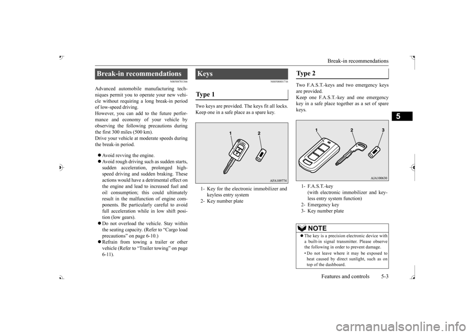
Two keys are provided. The keys fit all locks.Keep one in a safe place as a spare key.
Two F.A.S.T.-keys and two emergency keys are provided. Keep one F.A.S.T.-key and one emergency key in a safe pl
ace together as a set of spare
keys.
Break-in recommendations
Keys Ty p e 1 1- Key for the electronic immobilizer and
keyless entry system
2- Key number plate
Type 2 1- F.A.S.T.-key
(with electronic im
mobilizer and key-
less entry system function)
3- Key number plate
NOTE
The key is a precision
electronic device with
a built-in signal transm
itter. Please observe
the following in order to prevent damage. • Do not leave where it may be exposed to heat caused by direct
sunlight, such as on
top of the dashboard.
BK0239700US.book 3 ページ 2016年6月16日 木曜日 午前10時58分
Page 173 of 521

Service brake 5-92 Features and controls
5
N00517500275
Overuse of the brake can cause weakening, resulting in poor brake response and prema- ture wear of the brake pads. When driving down a long or steep hill, useengine braking
by downshifting.
N00517600364
Your vehicle is equipped with power brakes for more braking force with less brake pedal effort.Your brakes are designed to operate at full capacity, even if the power assist is not being used.If the power assist is not being used, the effort needed to press the brake pedal is greater. If you should lose the power assist for somereason, the brakes will still work. If the power brake unit or either of the two brake hydraulic systems stops working prop-erly, the rest of the brake system will still work, but the vehicle will not slow down as quickly.You will know this has happened if you find you need to press the brake down farther, or harder when slowing down or stopping, or ifthe brake warning light and the warning dis- play in the multi-information display come on.
To w i n g
CAUTION Do not tow 4-wheel drive vehicles with the front or rear wheels on the ground (Type A or Type B) as illustrate
d. This could result in
damage to the drivetrain, or unstable towing.If you tow 4-wheel drive vehicles, use TypeC or Type D equipment. Even in “4WD ECO” (Electronically con- trolled 4WD) or “AWC ECO” (S-AWC) drive mode, the vehicle cannot be towed with the front or the rear wheels on theground.
Jacking up a 4-wheel drive vehicle
WA R N I N G Do not crank the engine while jacking up the vehicle. The tire on the ground may turn and thevehicle may roll off the jack.
Service brake Brake pedal
WA R N I N G Do not leave any objects near the brake pedal or let a floor mat slide under it;doing so could prevent the full pedal stroke that would be necessary in an emergency. Make sure that the pedal canbe operated freely at all times. Make sure the floor mat is securely held in place.
CAUTION It is important not to drive the vehicle with your foot resting on the brake pedal whenbraking is not required.
This practice can
result in very high brake temperatures, pre- mature lining wear, a
nd possible damage to
the brakes.
Power brakes
BK0239700US.book 92 ページ 2016年6月16日 木曜日 午前10時58分
Page 178 of 521

Anti-lock braking system
Features and controls 5-97
5
N00517900240
The anti-lock braking system helps prevent the wheels from locking up when braking.This helps maintain vehicle drivability and steering wheel handling. When using the anti-lock brakes (sudden braking), steering is slightly different from normal driving conditions. Use the steering wheel carefully. Always keep a safe distance from the vehicle in front of you. Even if your vehi- cle is equipped with
the anti-lock braking
system, leave a greater braking distance when: • Driving on gravel or snow-coveredroads. • Driving on uneven road surfaces.
Operation of anti-lock braking system is not restricted situations where brakes areapplied suddenly. This system may also prevent the wheels from locking when you drive over manholes, steel roadworkplates, road markings
, or any uneven road
surface. When the anti-lock braking system is in use, you may feel the brake pedal vibrat- ing and hear a unique sound. It may also feel as if the pedal
resists being pressed.
In this situation, si
mply hold the brake
pedal down firmly. Do not pump thebrake, which will result in reduced braking performance.
CAUTION The brake assist system is not a device designed to exercise
braking force greater
than its capacity. Make sure to always keep asufficient distance be
tween your vehicle and
a vehicle in front of
you without relying too
much on the brake assist system.NOTE
Once the brake assist system is operational, it maintains great braking force even if the brake pedal is lightly released. To stop its operation, completely removeyour foot from the brake pedal. The brake assist system may become opera- tional when the brake pedal is fully depressed even if it
has not been depressed
suddenly. When the brake assist system is in use while driving, you may feel as if the depressedbrake pedal is soft, the pedal moves in small motions in conjunction with the operation noise, or the vehicle body and the steeringwheel vibrate. This occurs when the brake assist system is ope
rating normally and does
not indicate faulty
operation. Continue to
depress the brake pedal. You may hear an operation noise when the brake pedal is suddenl
y or fully depressed
while stationary. This does not indicate a malfunction and the brake assist system is operating normally.
When the anti-lock brake system warning light or only active st
ability control warning
light illuminate, the brake assist system innot functioning.
Anti-lock braking system Driving hints
NOTE
CAUTION The anti-lock braking system cannot prevent accidents. It is your
responsibility to take
safety precautions a
nd to drive carefully.
To prevent failure of the anti-lock braking system, be sure all 4 wheels and tires are the same size and the same type.NOTE
A whining sound is emitted from the engine compartment when driving immediately after starting the engine. These are the nor-mal sounds the anti-lock braking system makes when performing a self-check. It does not indicate
a malfunction.
BK0239700US.book 97 ページ 2016年6月16日 木曜日 午前10時58分
Page 274 of 521
Indicator light, warning light, and information screen display list (multi information display - Type 1)
Features and controls 5-193
5
N00558001289
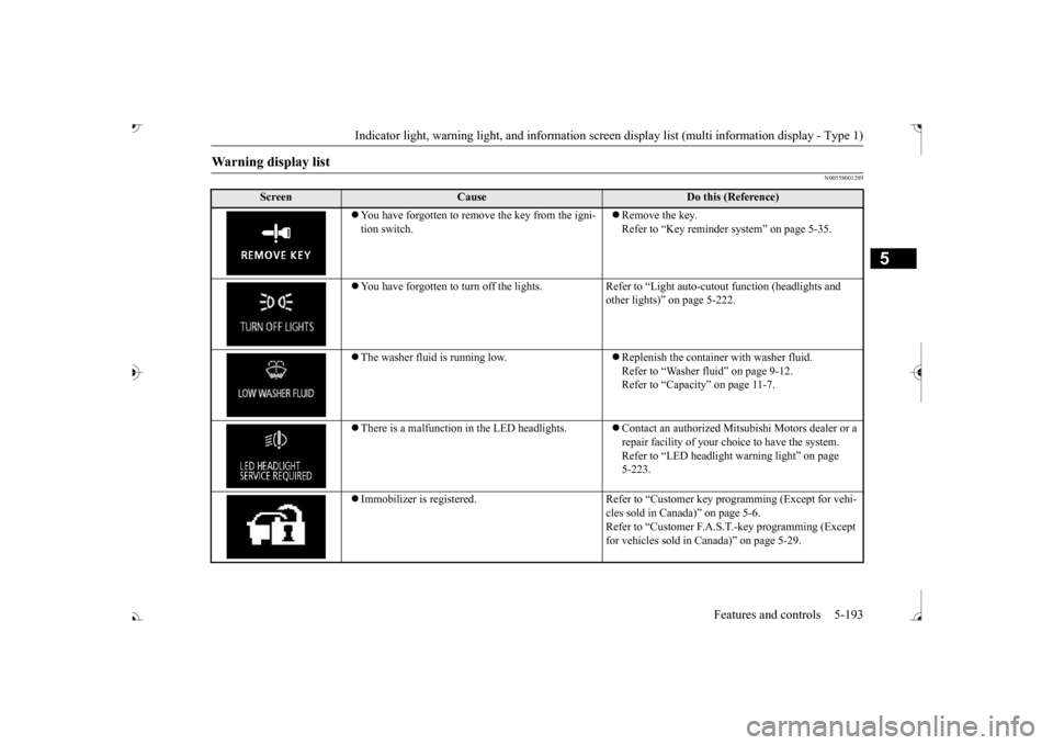
Warning display list
Screen
Cause
Do this (Reference)
ove the key from the igni-
tion switch.
Remove the key. Refer to “Key reminder system” on page 5-35.
You have forgotten to turn off
the lights. Refer to “Light auto
-cutout function (headlights and
other lights)” on page 5-222.
The washer fluid is running low.
Replenish the container with washer fluid. Refer to “Washer fluid” on page 9-12.Refer to “Capacity” on page 11-7.
There is a malfunction
in the LED headlights.
Contact an authorized Mitsubishi Motors dealer or a repair facility of your choi
ce to have the system.
Refer to “LED headlight
warning light” on page
5-223.
Immobilizer is registered. Refer to “Cus
tomer key programming (Except for vehi-
cles sold in Canada)” on page 5-6.Refer to “Customer F.A.S.
T.-key programming (Except
for vehicles sold in Canada)” on page 5-29.
BK0239700US.book 193 ページ 2016年6月16日 木曜日 午前10時58分
Page 300 of 521
Information screen display (Vehicle equipped with the multi information display - Type 1)
Features and controls 5-219
5
N00590300034
This light comes on when the washer fluid is running low.If the light comes on, replenish the container with washer fluid. Refer to “Washer fluid” on page 9-12.Refer to “Capacity” on page 11-7.
N00558301064 N00558401179
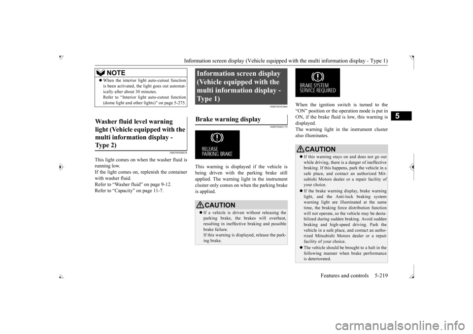
This warning is displayed if the vehicle is being driven with the parking brake stillapplied. The warning light in the instrument cluster only comes on when the parking brake is applied.
When the ignition switch is turned to the “ON” position or the operation mode is put inON, if the brake fluid is low, this warning is displayed. The warning light in the instrument cluster also illuminates.
NOTE
When the interior light
auto-cutout function
is been activated, th
e light goes out automat-
ically after about 30 minutes.Refer to “Interior light
auto-cutout function
(dome light and other
lights)” on page 5-275.
Washer fluid level warning light (Vehicle equipped with the multi information display - Type 2)
Information screen display (Vehicle equipped with the multi information display - Type 1) Brake warning display
CAUTION If a vehicle is driven
without releasing the
parking brake, the brakes will overheat, resulting in ineffectiv
e braking and possible
brake failure. If this warning is displayed, release the park- ing brake.
CAUTION If this warning stays on and does not go out while driving, there is
a danger of ineffective
braking. If this happens, park the vehicle in a safe place, and contac
t an authorized Mit-
subishi Motors dealer or
a repair facility of
your choice. If the brake warning display, brake warning light, and the Anti-lock braking system warning light are illuminated at the same time, the braking forc
e distribution function
will not operate, so the
vehicle may be desta-
bilized during sudden braking. Avoid sudden braking and high-speed driving. Park thevehicle in a safe place, and contact an autho- rized Mitsubishi Motors dealer or a repair facility of your choice. The vehicle should be br
ought to a halt in the
following manner when
brake performance
is deteriorated.
BK0239700US.book 219 ページ 2016年6月16日 木曜日 午前10時58分
Page 372 of 521
Loading information Driving safety 6-7
6
installed options, and
the tongue weight of
the trailer, if any, being towed. The tire andloading information placard located on the driver’s door sill of your vehicle will show how much weight it may properly carry. It is important to famil
iarize yourself with the
following terms before loading your vehicle: Vehicle maximum load on the tire: load on an individual tire that is determined by distributing to each axle its share of the maximum loaded vehicle weight anddividing by two. Vehicle normal load on the tire: load on an individual tire that is determined by dis-tributing to each axle its share of the curb weight, accessory weight, and normal occupant weight and dividing by two. Maximum loaded vehicle weight: the sum of - (a) Curb weight;(b) Accessory weight; (c) Vehicle capacity weight; and (d) Production options weight.
Curb weight: the weight of a motor vehi- cle with standard equipment including themaximum capacity of
fuel, oil, and cool-
ant. Accessory weight: the combined weight (in excess of those st
andard items which
may be replaced) of automatic transaxle, power steering, power brakes, power win-dows, power seats, radio, and heater, to the extent that these items are available as factory- installed equipment (whether installed or not). Vehicle capacity weight: the rated cargo and luggage load plus 150 lbs (68 kg) * times the vehicle’s designated seating capacity. Production options weight: the combined weight of those installed regular produc- tion options weighing over 5 lbs (2.3 kg)in excess of those standard items which they replace, not prev
iously considered in
curb weight or accessory weight, includ-ing heavy duty brakes,
ride levelers, roof
rack, heavy duty battery, and special trim. Normal occupant weight: 150 lbs (68 kg) * times the number of
specified occupants
(3 in the case of your vehicle) Occupant distribution:
Occupant distribu-
tion within the passenger compartment (In your vehicle the distribution is 2 in front, 1 in second row seat)
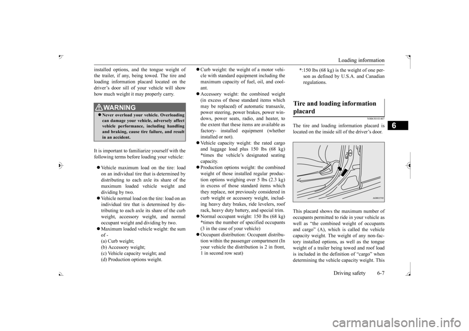
N00630101407
The tire and loading information placard islocated on the inside sill of the driver’s door. This placard shows the maximum number of occupants permitted to
ride in your vehicle as
well as “the combined
weight of occupants
and cargo” (A), which
is called the vehicle
capacity weight. The weight of any non-fac- tory installed options, as well as the tongueweight of a trailer being towed and roof load is included in the defi
nition of “cargo” when
determining the vehicle
capacity weight. This
WA R N I N GNever overload your ve
hicle. Overloading
can damage your vehicl
e, adversely affect
vehicle performance, including handling and braking, cause tire failure, and resultin an accident.
* :150 lbs (68 kg) is the weight of one per- son as defined by U.
S.A. and Canadian
regulations.
Tire and loading information placard
BK0239700US.book 7 ページ 2016年6月16日 木曜日 午前10時58分
Page 373 of 521
Loading information 6-8 Driving safety
6
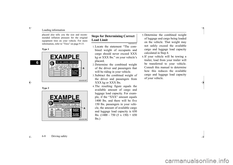
placard also tells you the size and recom- mended inflation pressure for the originalequipment tires on your vehicle. For more information, refer to “Tires” on page 9-15. Ty p e 1 Ty p e 2
N00630201222
1.Locate the statement “The com- bined weight of occupants and cargo should never exceed XXX kg or XXX lbs.” on your vehicle’splacard.2.Determine the combined weightof the driver and passengers thatwill be riding in your vehicle.3.Subtract the combined weight ofthe driver and passengers fromXXX kg or XXX lbs.4.The resulting figure equals theavailable amount of cargo andluggage load capacity. For exam- ple, if the “XXX” amount equals 1400 lbs. and there will be five150 lbs. passengers in your vehi- cle, the amount of available cargo and luggage load
capacity is 650
lbs. (1400 - 750 (5 x 150) = 650lbs.)
5.Determine the combined weightof luggage and cargo being loaded on the vehicle. That weight may not safely exceed the availablecargo and luggage load capacity calculated in Step 4.6.If your vehicle will be towing a trailer, load from your trailer will be transferred to your vehicle. Consult this manual to determinehow this reduces the available cargo and luggage load capacity of your vehicle.
Steps for Determining Correct Load Limit
BK0239700US.book 8 ページ 2016年6月16日 木曜日 午前10時58分